ABZ89FC5795Non-broadcast transmitter
Motorola Solutions, Inc.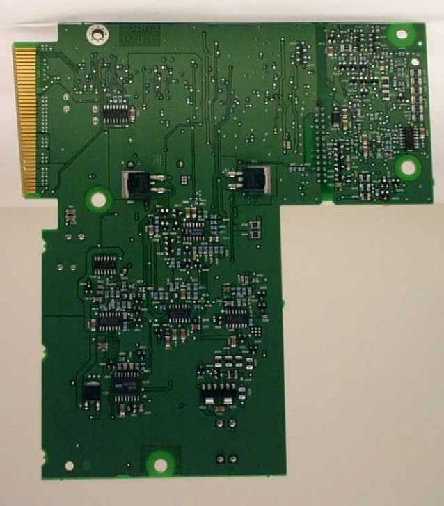
Click to zoom
Application Details
- Equipment Class
- TNB - Licensed Non-Broadcast Station Transmitter
- Date of Grant
- Jul 31, 2000
- Application Purpose
- Original Equipment
- Date of Application
- Jul 31, 2000
- Equipment Note
- Non-broadcast transmitter
- Frequency Range
- 851.00000000 - 870.00000000
- Company
- Motorola Solutions, Inc.
- Country
- United States
Documents & Files
Document Text
Text extracted from the exhibit documents filed with the FCC. Open a document above to read the original.
Users Manual
APPLICANT: MOTOROLA INC.EQUIPMENT TYPE: ABZ89FC5795 EXHIBIT 8 INSTRUCTION MANUALS The instruction and service manuals for this base radio are not available at this time. Upon request, manuals will be sent to the commission and/or telecommunication certification body (TCB) as soon as they become available. All of the descriptions and schematics in this filing are up to date and will be included in the instruction and/or service manuals. APPLICANT: MOTOROLA INC.EQUIPMENT TYPE: ABZ89FC5795 EXHIBIT 9 TUNE-UP PROCEDURE There is no field tune-up procedure. All adjustments are software controlled and are pre-set at the factory. Certain station operating parameters can be changed via radio service software (RSS) within predetermined limits. Examples include transmit / receiver operating frequencies and power level.
Attestation Statements
FCC ID: ABZ89FC5795July 24, 2000 Request for Confidentiality In accordance with 47 C.F.R. Section 0.459, we, Motorola Inc., hereby request confidentiality for the block diagrams, schematics, product descriptions, and circuit descriptions presented in Exhibit B. In support of the Request for Confidentiality, the following is stated: Enclosed within this application is technical information, which we deem to be trade secrets and proprietary. If made public, the information might be used to our disadvantage. To assist in assuring that we receive the full value of our product and protect its competitive posture, we respectfully request this grant of confidentiality. Motorola, Inc.
External Photos
APPLICANT: MOTOROLA INC.EQUIPMENT TYPE: ABZ89FC5795 EXHIBIT 12 PHOTOGRAPHS -- INDEX EXHIBIT DESCRIPTION 12A-1Rear of Station Including Location of the FCC ID Label 12A-2FCC Identification Label 12BLinear Simulcast Station Base Radio -- Front View 12CExciter Module, Component Side ** 12D-1Power Amplifier Module, Top View, Shields Removed 12D-2Power Amplifier Module, Heat Sink View 12E-1Power Supply Module, Cover Removed 12E-2Power Supply Module, Sub Board Removed ** 12E-3Power Supply Module, Sub Board Top Side 12E-4Power Supply Module, Sub Board Bottom Side 12FBase Radio Control Module, Component Side ** 12G-1Backplane Board, Front Side 12G-2Backplane Board, Back Side ** Indicates that there are no components and/or there is no significant circuitry on the back side of the board, therefore there is not a photo of the back side of the board included in this package. APPLICANT: MOTOROLA INC.EQUIPMENT TYPE: ABZ89FC5795 EXHIBIT 12A-1 Rear of Station Including Location of the FCC ID Label APPLICANT: MOTOROLA INC.EQUIPMENT TYPE: ABZ89FC5795 EXHIBIT 12A-2 FCC Identification Label APPLICANT: MOTOROLA INC.EQUIPMENT TYPE: ABZ89FC5795 EXHIBIT 12B Linear Simulcast Station Base Radio -- Front View APPLICANT: MOTOROLA INC.EQUIPMENT TYPE: ABZ89FC5795 EXHIBIT 12C Exciter Module, Component Side APPLICANT: MOTOROLA INC.EQUIPMENT TYPE: ABZ89FC5795 EXHIBIT 12D-1 Power Amplifier Module, Top View, Shields Removed APPLICANT: MOTOROLA INC.EQUIPMENT TYPE: ABZ89FC5795 EXHIBIT 12D-2 Power Amplifier Module, Heat Sink View APPLICANT: MOTOROLA INC.EQUIPMENT TYPE: ABZ89FC5795 EXHIBIT 12E-1 Power Supply Module, Cover Removed APPLICANT: MOTOROLA INC.EQUIPMENT TYPE: ABZ89FC5795 EXHIBIT 12E-2 Power Supply Module, Component Side, Sub Board Removed APPLICANT: MOTOROLA INC.EQUIPMENT TYPE: ABZ89FC5795 EXHIBIT 12E-3 Power Supply Module, Sub Board Top Side APPLICANT: MOTOROLA INC.EQUIPMENT TYPE: ABZ89FC5795 EXHIBIT 12E-4 Power Supply Module, Sub Board Bottom Side APPLICANT: MOTOROLA INC.EQUIPMENT TYPE: ABZ89FC5795 EXHIBIT 12F Base Radio Control Module, Component Side APPLICANT: MOTOROLA INC.EQUIPMENT TYPE: ABZ89FC5795 EXHIBIT 12G-1 Backplane Board, Front Side APPLICANT: MOTOROLA INC.EQUIPMENT TYPE: ABZ89FC5795 EXHIBIT 12G-2 Backplane Board, Back Side
ID Label/Location Info
APPLICANT: MOTOROLA INC.EQUIPMENT TYPE: ABZ89FC5795 EXHIBIT 2 IDENTIFICATION LABEL LOCATION X See The Attached Photographs (EXHIBIT 12A-1, EXHIBIT 12A-2) X Back Of Radio Back Of Radio Under Belt Clip APPLICANT: MOTOROLA INC.EQUIPMENT TYPE: ABZ89FC5795 EXHIBIT 12A-1 Rear of Station Including Location of the FCC ID Label APPLICANT: MOTOROLA INC.EQUIPMENT TYPE: ABZ89FC5795 EXHIBIT 12A-2 FCC Identification Label
Internal Photos
APPLICANT: MOTOROLA INC.EQUIPMENT TYPE: ABZ89FC5795 EXHIBIT 12 PHOTOGRAPHS -- INDEX EXHIBIT DESCRIPTION 12A-1Rear of Station Including Location of the FCC ID Label 12A-2FCC Identification Label 12BLinear Simulcast Station Base Radio -- Front View 12CExciter Module, Component Side ** 12D-1Power Amplifier Module, Top View, Shields Removed 12D-2Power Amplifier Module, Heat Sink View 12E-1Power Supply Module, Cover Removed 12E-2Power Supply Module, Sub Board Removed ** 12E-3Power Supply Module, Sub Board Top Side 12E-4Power Supply Module, Sub Board Bottom Side 12FBase Radio Control Module, Component Side ** 12G-1Backplane Board, Front Side 12G-2Backplane Board, Back Side ** Indicates that there are no components and/or there is no significant circuitry on the back side of the board, therefore there is not a photo of the back side of the board included in this package. APPLICANT: MOTOROLA INC.EQUIPMENT TYPE: ABZ89FC5795 EXHIBIT 12A-1 Rear of Station Including Location of the FCC ID Label APPLICANT: MOTOROLA INC.EQUIPMENT TYPE: ABZ89FC5795 EXHIBIT 12A-2 FCC Identification Label APPLICANT: MOTOROLA INC.EQUIPMENT TYPE: ABZ89FC5795 EXHIBIT 12B Linear Simulcast Station Base Radio -- Front View APPLICANT: MOTOROLA INC.EQUIPMENT TYPE: ABZ89FC5795 EXHIBIT 12C Exciter Module, Component Side APPLICANT: MOTOROLA INC.EQUIPMENT TYPE: ABZ89FC5795 EXHIBIT 12D-1 Power Amplifier Module, Top View, Shields Removed APPLICANT: MOTOROLA INC.EQUIPMENT TYPE: ABZ89FC5795 EXHIBIT 12D-2 Power Amplifier Module, Heat Sink View APPLICANT: MOTOROLA INC.EQUIPMENT TYPE: ABZ89FC5795 EXHIBIT 12E-1 Power Supply Module, Cover Removed APPLICANT: MOTOROLA INC.EQUIPMENT TYPE: ABZ89FC5795 EXHIBIT 12E-2 Power Supply Module, Component Side, Sub Board Removed APPLICANT: MOTOROLA INC.EQUIPMENT TYPE: ABZ89FC5795 EXHIBIT 12E-3 Power Supply Module, Sub Board Top Side APPLICANT: MOTOROLA INC.EQUIPMENT TYPE: ABZ89FC5795 EXHIBIT 12E-4 Power Supply Module, Sub Board Bottom Side APPLICANT: MOTOROLA INC.EQUIPMENT TYPE: ABZ89FC5795 EXHIBIT 12F Base Radio Control Module, Component Side APPLICANT: MOTOROLA INC.EQUIPMENT TYPE: ABZ89FC5795 EXHIBIT 12G-1 Backplane Board, Front Side APPLICANT: MOTOROLA INC.EQUIPMENT TYPE: ABZ89FC5795 EXHIBIT 12G-2 Backplane Board, Back Side
Parts List/Tune Up Info
APPLICANT: MOTOROLA INC.EQUIPMENT TYPE: ABZ89FC5795 EXHIBIT 8 INSTRUCTION MANUALS The instruction and service manuals for this base radio are not available at this time. Upon request, manuals will be sent to the commission and/or telecommunication certification body (TCB) as soon as they become available. All of the descriptions and schematics in this filing are up to date and will be included in the instruction and/or service manuals. APPLICANT: MOTOROLA INC.EQUIPMENT TYPE: ABZ89FC5795 EXHIBIT 9 TUNE-UP PROCEDURE There is no field tune-up procedure. All adjustments are software controlled and are pre-set at the factory. Certain station operating parameters can be changed via radio service software (RSS) within predetermined limits. Examples include transmit / receiver operating frequencies and power level.
Test Report
APPLICANT: MOTOROLA INC.EQUIPMENT TYPE: ABZ89FC5795 EXHIBIT 1 STATEMENT OF CERTIFICATION The technical data supplied with this application, having been taken under my supervision is hereby duly certified. The following is a statement of my qualifications: College Degree:BSEE, Valparaiso University, Valparaiso, Indiana, USA MSEE, Illinois Institute of Technology, Chicago, Illinois, USA __18___ years of Design and Development experience in the field of two-way radio communication. NAME: Ken Weiss SIGNATURE: ___________________________ DATE: July 21, 2000 POSITION: Lead Electrical Engineer I hereby certify that the above application was prepared under my direction and that to the best of my knowledge and belief, the facts set forth in the application and accompanying technical data are true and correct: NAME: Ron Wegner SIGNATURE: ___________________________ DATE: July 21, 2000 POSITION: Engineering Manager APPLICANT: MOTOROLA INC.EQUIPMENT TYPE: ABZ89FC5795 EXHIBIT 11 SUBMITTED MEASURED DATA -- INDEX EXHIBIT DESCRIPTION 11ARF Output-Data 11BOccupied Bandwidth 11CConducted Spurious Emissions: Setup, Specifications, Index 11C-1Conducted Spurious Emissions, Harmonics, Power Output at 100 Watts 11C-2Conducted Spurious Emissions, Harmonics, Power Output at 5 Watts 11C-3Conducted Spurious Emissions, Close-In, Power Output at 100 Watts 11C-4Conducted Spurious Emissions, Close-In, Power Output at 5 Watts 11DRadiated Spurious Emissions: Setup, Specifications, Index 11D-1Radiated Spurious Emissions, Power Output at 100 Watts 11D-2Radiated Spurious Emissions, Power Output at 5 Watts 11EFrequency Stability: Setup, Specifications, Index 11E-1Frequency Stability Vs Temperature 11E-2Frequency Stability Vs Voltage APPLICANT: MOTOROLA INC.EQUIPMENT TYPE: ABZ89FC5795 EXHIBIT 11A RF POWER OUTPUT DATA The RF power output was measured with the indicated voltage applied to and current into the final RF amplifying device. Measured RF output100Watts Normal DC Voltage28.5Volts Normal DC Current14.29Amperes Input power for final RF amplifying device(s)407.3Watts Primary Supply Voltage48Volts DC Minimum Measured RF output5Watts Normal DC Voltage28.5Volts Normal DC Current3.55Amperes Input power for final RF amplifying device(s)101.2Watts Primary Supply Voltage48Volts DC APPLICANT: MOTOROLA INC.EQUIPMENT TYPE: ABZ89FC5795 EXHIBIT 11B (Sheet 1 of 2) OCCUPIED BANDWIDTH Modulation Type:Widepulse QPSK – 9600 bps Random Data Emission Designator:8K70D1W Channelization:12.5 kHz SPECIFICATION REQUIREMENT: § 90.210Emission limits: For transmitters designed to operate with a 12.5 kHz channel bandwidth, any emission must be attenuated below the power (P) of the highest emission contained within the authorized bandwidth as follows: (1) On any frequency from the center of the authorized bandwidth (f 0 ) to 5.625 kHz removed from f 0 : Zero dB. (2) On any frequency removed from the center of the authorized bandwidth by a displacement frequency (f d in kHz) of more than 5.625 kHz but no more than 12.5 kHz: At least 7.27 *( f d –2.88 kHz) dB. (3) On any frequency removed from the center of the authorized bandwidth by a displacement frequency (f d in kHz) of more than 12.5 kHz: At least 50 plus 10 log 10 (P) decibels or 70 decibels, whichever is the lesser attenuation. (4) The reference level for showing compliance with the emission mask shall be established using a resolution bandwidth sufficiently wide to capture the true peak emission of the equipment under test. Necessary Bandwidth Calculation: The necessary bandwidth of the modulation signal is not calculable per the formulas defined in 47 CFR 2.202 (b). Specifically, although the modulation for this emission is a composite modulation, the equations given in the composite tables in 2.202 are not applicable since none of them adequately approximate the form of digital modulation used. The necessary bandwidth of 8.70 kHz is based upon a 99% power measurement of the transmitter spectrum, per 2.202 (a). Measurement Setting and Procedure, per TIA/EIA-102.CAAA, Section 2.2.5: Reference Calibration Analyzer Settings: Horizontal:12 kHz per DivisionResolution Bandwidth:30 kHz Vertical:10 dB per DivisionVideo Bandwidth:30 kHz Sweep Time:75 Seconds (<2000 Hz / Second)Span:120 kHz Detector Mode:Positive Peak Emission Measurement Analyzer Settings: Horizontal:12 kHz per DivisionResolution Bandwidth:100 Hz Vertical:10 dB per DivisionVideo Bandwidth:1 kHz Sweep Time:75 Seconds (<2000 Hz / Second)Span:120 kHz Detector Mode:Positive Peak Test Procedure: 1)Adjust the spectrum analyzer per the values specified in the Reference Calibration Analyzer Settings. 2)Modulate the transmitter with the appropriate signaling pattern, (psuedorandom data) and key the transmitter. Use the analyzer controls to set this signal to the full-scale reference line. Allow the analyzer to sweep. 3)Adjust the analyzer per the Emission Measurement Analyzer Settings. 4)Allow the analyzer to sweep, and record the resultant emission levels. 5)Plot the resulting analyzer trace and the emission mask limit, add text and labeling as appropriate. OCCUPIED BANDWIDTH -- 12.5 kHz CHANNELS -100 -90 -80 -70 -60 -50 -40 -30 -20 -10 0 -60-50-40-30-20-100102030405060 CENTER 860.0125 MHz RES BW 30 kHz RES BW 100 Hz D-Mask 10 dB/ POS PK RES BW 100 Hz REF 22.1 dBmATTEN 40 dB VID BW 1 kHzSWP 75 sec SPAN 120 kHz LOG PAGE: 885796 DATE: 6/15/00 NAME: Ferdie DeLeon SIGNATURE: _____________________ APPLICANT: MOTOROLA, INC. EXHIBIT 11B (Sheet 2 of 2) EQUIPMENT TYPE: ABZ89FC5795 APPLICANT: MOTOROLA INC.EQUIPMENT TYPE: ABZ89FC5795 EXHIBIT 11C CONDUCTED SPURIOUS EMISSIONS SPECIFICATION REQUIREMENT: Reference: Part 90.210 (Emission Mask D) On any frequency displacement of more than 12.5 kHz removed from the center of the authorized bandwidth, the power of any emission shall be attenuated below the transmitter power (P) by at least 50 plus 10 log 10 (Mean output power in Watts) decibels or 70 decibels, whichever is the lesser attenuation. For this tra…
Text truncated - open the document above for the full version.
Contact Information
Applicant
Matthew Nawrocki
Non-Technical Contact
Motorola Inc.Ronald A Wagner
847 576-5711
Technical Specifications
| # | Rule Parts | Frequency Range | Power Output | Emission | Tolerance |
|---|---|---|---|---|---|
| 1 | 90 | 851 MHz - 870 MHz | 100 W | 8K70D1W | 1.0000000000 ppm |
Other Applications from Motorola Solutions, Inc.

ABZ89FT4940
Aug 06, 2026Non Broadcast Transmitter
Equipment Class
TNB - Licensed Non-Broadcast Station TransmitterABZ89FT4950
Jun 25, 2026Non-Broadcast Transmitter
Equipment Class
TNB - Licensed Non-Broadcast Station TransmitterABZ89FT5901
Jun 20, 2024Non Broadcast Transmitter
Equipment Class
TNB - Licensed Non-Broadcast Station Transmitter
ABZ99FT5101B
May 02, 2023Non Broadcast Transmitter
Equipment Class
PCB - PCS Licensed Transmitter
ABZ99FT3095B
Mar 26, 2023Non Broadcast Transmitter
Equipment Class
TNB - Licensed Non-Broadcast Station Transmitter