ABZ89FC5805Non-Broadcast Transmitter
Motorola Solutions, Inc.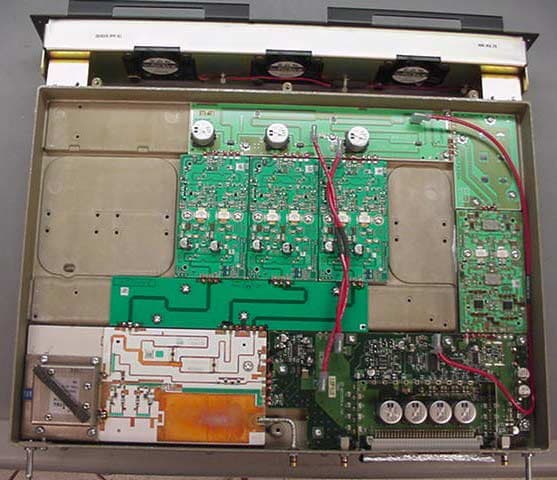
Click to zoom
Application Details
- Equipment Class
- TNB - Licensed Non-Broadcast Station Transmitter
- Date of Grant
- Mar 26, 2003
- Application Purpose
- Original Equipment
- Date of Application
- Mar 26, 2003
- Equipment Note
- Non-Broadcast Transmitter
- Frequency Range
- 764.00000000 - 776.00000000
- Company
- Motorola Solutions, Inc.
- Country
- United States
Documents & Files
Document Text
Text extracted from the exhibit documents filed with the FCC. Open a document above to read the original.
Users Manual
APPLICANT: MOTOROLA INC. EQUIPMENT TYPE: ABZ89FC5805 EXHIBIT 9 TUNE-UP PROCEDURE There is no field tune-up procedure. All adjustments are software controlled and are pre-set at the factory. Certain station operating parameters can be changed via Man Machine Interface (MMI) through the BRC RS232 port within predetermined limits. Examples include transmit / receiver operating frequencies and power level. APPLICANT: MOTOROLA INC. EQUIPMENT TYPE: ABZ89FC5805 EXHIBIT 9 Tune Up Procedure This exhibit contains the tune-up procedure as it will appear in the Astro® 25 system release 6.2 Simulcast Configuration Manual. The following adjustments comprise the transmitter setups. 1. Reference oscillator installation 2. Setting transmitter frequency and power level. 3. Measuring channel interference 4. Measuring the transmitter metering points 5. Measuring the transmitter frequency error Test Equipment Description Recommended Model Service Monitor Motorola R-2001 or equivalent PC with CSS Software Procedure CSS Port: 9-pin serial cable with D connector is provided on the station control module front panel to allow service personnel to connect a PC loaded with the Configuration Service Software (CSS) and perform programming and maintenance tasks via the RS232 port. The following pages of this exhibit show the important alignment screens. Exhibit Description 9A Installing reference oscillator 9B Configuring channel frequency and power level 9C Measuring channel interference 9D Measuring the transmitter metering points 9E Measuring the transmitter frequency error 3-468P8100XYXX-OAPRIL 2003 PRELIMINARY Internal Review (First Draft - 50% to 60% Complete) RF SITE EQUIPMENT CONFIGURATIONCHAPTER 3: SIMULCAST REMOTE SITE CONFIGURATION . . . . . . . . . . . . . . . . . . . . . . . . . . . . . . . . . . . . . RF SITE EQUIPMENT CONFIGURATION The following sections provide information about programming the devices that provide the RF interface (simulcast base radio) to the subscriber radios in your system and the devices that support the RF interface. TRAK 9100 SIMULCAST SITE REFERENCE See “TRAK 9100 Simulcast Site Reference Configuration” on page 2-20 for a full description of the configuration procedures that cover the general configuration points. This section provides only the specific settings required for the remote site device. At the digital simulcast subsystem remote sites, the TRAK 9100 provides 1 pps + 5 Mpps composite signals to the simulcast base radio. For a total of 30 channels, a TRAK 9100 SSR with two Digital Distribution Modules (DDM) configured for composite signals is required. Each composite signal can drive up to six STR 3000 Base Radios. A 50 ohm impedance must terminate the end of a daisy chain. The 50 ohm load is installed at the STR 3000 Base Radio’s composite input terminal. STR 3000 SIMULCAST BASE RADIO The information provided in this section is for all simulcast base radios installed in the digital simulcast subsystem at remote and co-located remote sites. Using the TTY port, connect to the simulcast base radios, and program the IP address required for this particular station on this channel number at this subsite. IP address information should be obtained from your Motorola Field Representative. Using Configuration/Service Software (CSS), program the proper operating frequency for the station and verify proper RF alignment. Do this for all channels at all subsites. Table 3-1 gives an overview of information that is configured. Using the CSS Station Configuration tab, set Simulcast Operation to Enabled. NOTE Some fields in the CSS dialog boxes are marked with an asterisk (*). This indicates a field that can be overwritten from the User Configuration Manager (UCM). 3-668P8100XYXX-OAPRIL 2003 PRELIMINARY Internal Review (First Draft - 50% to 60% Complete) RF SITE EQUIPMENT CONFIGURATIONCHAPTER 3: SIMULCAST REMOTE SITE CONFIGURATION FIGURE 3-7 BASE RADIO HARDWARE CONFIGURATION SCREEN Station Configuration ScreenProvides for the simulcast base radio’s specific station configuration. See the online documentation provided with the CSS for specific procedures. F IGURE 3-8 BASE RADIO STATION CONFIGURATION SCREEN TABLE 3-1 SIMULCAST BASE RADIO CONFIGURATION SCREENS IN CSS (CONTINUED) ScreenDescription 68P8100XYXX-OAPRIL 20033-9 PRELIMINARY Internal Review (First Draft - 50% to 60% Complete) SIMULCAST CONFIGURATION ILLEGAL CARRIER DETERMINATION AND BASE RADIO MEASUREMENT MEASURING CHANNEL INTERFERENCE The STR 3000 Simulcast Base Radios log interfering carrier levels that surpass the RF threshold value to the station error log. These logs can be used to determine periodic interfering carriers that are not present long enough to trigger the Carrier Malfunction Timer. These logs should also be checked after any changes are made to the site that affect the site noise floor. An example of this type of change would be seen when a new customer in the immediate area is using the same frequency band. SETTING THE STR 3000 SIMULCAST BASE RADIO RF T HRESHOLD VALUE FIELD The RF Threshold Value field appears on the Station Configuration tab of the STR 3000 Simulcast Base Radio window. This field defines the level (in dBm) above which the received signal is considered to be an illegal carrier, if this STR 3000 Simulcast Base Radio is not assigned to a call. Procedure 3-1 describes the steps to set the RF Threshold Value field. P ROCEDURE 3-1 HOW TO SET THE STR 3000 SIMULCAST BASE RADIO RF THRESHOLD V ALUE FIELD 1In the CSS application, select STR 3000 Simulcast Base Radio. Result: The STR 3000 Simulcast Base Radio window appears (Figure 3-10). F IGURE 3-10 STR 3000 SIMULCAST BASE RADIO WINDOW SCREEN 3-2068P8100XYXX-OAPRIL 2003 PRELIMINARY Internal Review (First Draft - 50% to 60% Complete) ILLEGAL CARRIER DETERMINATION AND BASE RADIO MEASUREMENTCHAPTER 3: SIMULCAST REMOTE SITE CONFIGURATION MONITORING THE TRANSMITTER METERING POINTS Perform Procedure 3-4 to monitor the transmitter metering points. P ROCEDURE …
Text truncated - open the document above for the full version.
Users Manual
APPLICANT: MOTOROLA INC. EQUIPMENT TYPE: ABZ89FC5805 EXHIBIT 8 INSTRUCTION MANUALS The Preliminary Installation manual for this base radio is provided. Upon request, final manuals will be sent to the commission and/or telecommunication certification body (TCB) as soon as they become available. All of the descriptions and schematics in this filing are up to date and will be included in the instruction and/or service manuals. APPLICANT: MOTOROLA INC. EQUIPMENT TYPE: ABZ89FC5805 EXHIBIT 8 INSTRUCTION MANUALS Draft copy of the of the front matter of the following instruction manual is enclosed with this submission: 68P81003Y71-O ........................................................ 6.2 First Draft for Simulcast Hardware Installation Other system and radio / configuration service software manuals are available to support the product and system in operation. They can be provided to the Commission upon request. 6.2 First Draft for Simulcast Ha rdw a r e I n s t a l l a t i o n © November 2002 Motorola, Inc.68P81003Y71-O All Rights ReservedNovember 2002 Pr inted in U.S.A. Computer Software Copyrights The Motorola products described in this document include a copyrighted Motorola computer program. Laws in the United States and other countries, as well as International Treaties, preserve for Motorola the exclusive rights for Motorola’s copyrighted computer programs, including the exclusive right to copy, repro- duce, distribute, or otherwise transfer said computer program(s). Accordingly, the copyrighted Motorola computer programs contained in this document may not be copied, decompiled, reverse engineered, or reproduced in any manner and on or within any media without the express written permission of Motorola. Furthermore, the purchase of Motorola products shall not be deemed to grant either directly or by implication, estoppel, or otherwise, any license under the copyrights, patents, or patent applications of Motorola, except for the normal non-exclusive, royalty-free license to use that arises by operationof law in the sale of a product. Document Copyrights © Motorola, Inc. All rights reserved. No duplication or distribution of this document or any portion thereof shall take place without the express written permission of Motorola. No part ofthis document may be reproduced, distributed, or transmitted in any form or by any means, electronic or mechanical, for any purpose without the express written permission of Motorola. To order additional copies of this document contact your Motorola sales representative. Disclaimer The information in this document is carefully examined, and is believed to be entirely reliable. However, no responsibility is assumed for inaccuracies. Further- more, Motorola reserves the right to make changes to any products herein to improve readability, function, or design. Motorola does not assume any liability arising out of the applications or use of any product or circuit described herein; neither does it cover any license under its patent rights nor the rights of others. Trademark Information The following are registered trademarks of Motorola, Inc.: ASTRO, ASTRO-TAC, ASTRO 25, EMBASSY, FLASHport, FullVision, INTELLIREPEATER, MAXTRAC, Motorola, the Motorola logo, MSF 5000, QUANTAR, QUANTRO, SECURENET, SMARTNET, SMARTZONE, SPECTRA, and STARTSITE. The following are Motorola trademarks: CENTRACOM Series, CENTRACOM Gold Series, CENTRACOM Series II, CENTRACOM Series II Plus, Cisco, CoveragePLUS, DIGITAC, DVP, Max-Fax, MDC-600, Micor, MOSCAD, MSF10000, MTS 2000, OmniLink, Private Conversation, SABER, SMARTNET II, SmartWorks, and Wireless Network Gateway. HP, HP-UX, and Hewlett Packard are registeredtrademarks of Hewlett-Packard Corporation. UNIX is a registered trademark of The Open Group in the United States and other countries. Any other brand or product names are trademarks or registered trademarks of their respective holders. WARRANTY Limited Software Warranty For the first ninety (90) days following its initial shipment, Motorola warrants that when properly used, its software will be free from reproducibledefects that cause a material variance from its published specification. However, Motorola does not warrant that program operation will be uninterrupted or error- free, that each defect will be corrected, or that any program will meet Licensee’s particular requirements. This warranty does not cover an item of Software (i) used in other than its normal and customary manner; (ii) subjected to misuse; or (iii) subjected to modi- fications by Licensee or by any party other than Motorola without the prior written consent of Motorola. Limited Media Warranty For the first ninety (90) days following its initial shipment, Motorola warrants that the media carrying the software will be free from defects that damage the performance of the software. Motorola will replace any damaged media free of charge during the warranty period. Warranted media is limited to that which is used to transport the software (such as floppy disks and authorization key). PROMs that may store the software in equipment are not covered under this warranty. Limitation of Liability Motorola’s total liability and Licensee’s sole remedy for any warranted software shall be limited to, at Motorola’s option, software replacement orthe payment of Licensee’s actual damages, not to exceed the total licensed charge paid by Licensee to Motorola for the item of software that caused the damage. The warranties set forth above extendonly to the first licensee. Subsequent transferees accept these programs "as is" and without warranties of any kind.This warranty is given in lieu of all other warranties, express or implied, including, without limitation, the warranties of merchantability and fitnessfor a particular purpose. In no event shall Motorola be liable for special, incidental, or consequential damages (including, without limitation, loss of use, time or data, inconvenience, commercial loss, and lost profits or sav…
Text truncated - open the document above for the full version.
Users Manual
Simulcast Hardware InstallationConnecting Power to the STR 3000 Rack Do NOT daisy-chain multiple equipment cabinet grounds using a single ground wire. Doing so increases the overall inductance of the ground wire which can distribute surge energy among the cabinets instead of to the master ground bar. SeeStandards and Guidelines for Communications Sites(68P81089E50) for detailed information on grounding the rack. Connecting Power to the STR 3000 Rack The STR 3000 rack requires a -48 VDC, which is provided by the DC power distribution. Figure 5-4 shows the typical connections for power to the STR 3000 rack. Figure 5-4Typical Power Connections for the STR 3000 Rack Determining Power Connection Wire Size Wire size recommendations contained herein reflect Motorola engineering requirements for proper system operation. Local regulations should be adhered to and will supersede any other specifications in this manual, where applicable. Donotusewiresmallerthan16mm2CSA(5AWG).Cableloopvoltagedrop must not exceed 500 mV for cabling of the -48 VDC and DC return leads. 68P81003Y71-O November 20025-9 Installing the Expansion CabinetsChapter 5: Installing the Digital Simulcast Remote Site (10Base-2) For a standard installation, the equipment cabinet is located adjacent to the power supply equipment with a cable loop length less than 10.67 m (35 ft.). The “loop length” refers to the combined length of the -48 VDC lead and the DC return lead. For example, a cabinet which needs 4.87 m (16 ft.) of wire between the power supply equipment and equipment cabinets has a total loop length of 9.75 m (32 ft.). Table 5-3 lists the required wire sizes for various installations. Table 5-3Power Connections Wire Size Loop Length Wire Size 15.2m(50ft.)orless16mm 2 CSA (5 AWG) 15.2 - 24.8 m (50 - 80 ft.)25 mm 2 CSA (4 AWG) 24.8 - 36.6 m (80 - 120 ft.)35 mm 2 CSA (2 AWG) Installing the Expansion Cabinets If an expansion cabinet is required, the expansioncabinet must be located to the right of the prime cabinet (Se e Figure 5-5). The two cavity combiners are connected to their respective side of the phasing harness. The phasing harness bracket for the transmit combiner is mounted to the expansion rack. The power monitor unit (PMU) is connected to the post filter, which is connected to the top of the phasing harness. 5-10 68P81003Y71-O November 2002 Simulcast Hardware InstallationInstalling the Expansion Cabinets Figure 5-5Placement of Expansion Cabinets 68P81003Y71-O November 20025-11 Cabling the STR 3000 Base Radio RackChapter 5: Installing the Digital Simulcast Remote Site (10Base-2) Cabling the STR 3000 Base Radio Rack The components of the STR 3000 Base Radio rack are shipped as one unit and do not require separate cabling during the initial installation. For more information on how to cable each component within the rack, see Volume 8, Field Replaceable Units and Entities (68P81004Y55). From the rack, make the following connections to the system: •"Connecting the Ethernet Cables" on page 5-12 •"Connecting the Transmit Cables" on page 5-13 •"Connecting the Receive Cables" on page 5-14 •"Connecting the V.24 Cabling" on page 5-16 •"Connecting Cables for a Co-Located Remote Site" on page 5-17 Connecting the Ethernet Cables Table 5-4 lists the Ethernet connections from the STR 3000 rack to the system. Table 5-4Ethernet Connections from the STR 3000 Rack From STR 3000 Rack Destination Device Port Connector Type Port Connector Type Description Ethernet Out port on the junction panel in the f irst cabinet BNC Port1onHub RJ45 Ethernet LAN connection Ethernet Out port on the junction panel in succeeding cabinets BNC Ethernet out on preceding panel RJ45 Ethernet LAN connection Ethernet Out port on the junc tion panel in the last cabinet BNC with 50 ohm terminati on Terminator on Ethernet O ut BNC LAN termination Both ends of the Ethernet cabling for a rack must be terminated. 5-12 68P81003Y71-O November 2002 Simulcast Hardware InstallationConnecting the Transmit Cables The DLN1269A base radio controller module can be configured for both 10Base-2 and 10Base-T operation. The site must be all 10Base-2 or all 10Base-T. You cannot mix configurations within a site. Connecting the Transmit Cables Table 5-5 lists the transmit connections from the STR 3000 rack to the system. For more detail on internal cabling, see Volume 8,Field Replaceable Units and Entities(68P81004Y55). Table 5-5Connections for the Transmit Cables From STR 3000 Rack Destination Device Port Connector Type Port Connector Type Description Transmit an tenna 7/16 DIN N Ty pe Antenna 7/16 DIN N Ty pe Transmit ou tput from the STR 3000 to the transmit antenna. Fi gure 5-6 shows the transmit cabling layout for a six-channel STR 3000 Base Radio rack. 68P81003Y71-O November 20025-13 Connecting the Receive CablesChapter 5: Installing the Digital Simulcast Remote Site (10Base-2) Figure 5-6Transmit Cabling in the STR 3000 Rack Connecting the Receive Cables Table 5-6 lists the receive connectionsfrom the system into the STR 3000 rack. 5-14 68P81003Y71-O November 2002 Simulcast Hardware InstallationConnecting the Receive Cables Table 5-6Connections for the Receive Cables From STR 3000 Rack Destination Device Port Connector Type Port Connector Type Description Rx In (Signal IN on figure) 7/16 DIN N Type Receive antenna 7/16 DINN Type Receives antenna input into the STR 3000 rack Figure 5-7 shows the receive cable connections for the STR 3000 rack. Fig ure 5-7Receive Cabling in the STR 3000 Rack 68P81003Y71-O November 20025-15 Connecting the V.24 CablingChapter 5: Installing the Digital Simulcast Remote Site (10Base-2) Connecting the V.24 Cabling Table 5-7 lists the V.24 audio connections for the STR 3000 rack. Table 5-7V.24 Cable Connections From STR 3000 Rack Destination De vice Port Connector Type Port Connector Type Description Port PNL 1 RJ45 (V.24)Channel Bank 1 , SRU Port 1 RJ45 (V.24)Connection to the prime site. Port PNL 2 RJ45 (V.24)Channel Bank 1, SRU Port 2 RJ45 (V.24)Conn…
Text truncated - open the document above for the full version.
External Photos
APPLICANT: MOTOROLA INC. EQUIPMENT TYPE: ABZ89FC5805 EXHIBIT 12 PHOTOGRAPHS -- INDEX EXHIBIT DESCRIPTION 12A-1 Rear of Station Including Location of the FCC ID Label 12A-2 FCC Identification Label 12B Linear Simulcast Station Base Radio -- Front View 12C Exciter Module, Component Side ** 12D-1 Power Amplifier Module, Top View, Shields Removed 12D-2 Power Amplifier Module, Heat Sink View 12E-1 Power Supply Module, Cover Removed 12E-2 Power Supply Module, Sub Board Removed ** 12E-3 Power Supply Module, Sub Board Top Side 12E-4 Power Supply Module, Sub Board Bottom Side 12F Base Radio Control Module, Component Side ** 12G-1 Backplane Board, Front Side 12G-2 Backplane Board, Back Side 12H Transmit Combiner, 2:1 ** Indicates that there are no components and/or there is no significant circuitry on the backside of the board, therefore there is not a photo of the back side of the board included in this package. APPLICANT: MOTOROLA INC. EQUIPMENT TYPE: ABZ89FC5805 EXHIBIT 12A-1 Rear of Station Including Location of the FCC ID Label APPLICANT: MOTOROLA INC. EQUIPMENT TYPE: ABZ89FC5805 EXHIBIT 12A-2 FCC Identification Label APPLICANT: MOTOROLA INC. EQUIPMENT TYPE: ABZ89FC5805 EXHIBIT 12B Linear Simulcast Station Base Radio -- Front View APPLICANT: MOTOROLA INC. EQUIPMENT TYPE: ABZ89FC5805 EXHIBIT 12C Exciter Module, Component Side APPLICANT: MOTOROLA INC. EQUIPMENT TYPE: ABZ89FC5805 EXHIBIT 12D-1 Power Amplifier Module, Top View, Shields Removed APPLICANT: MOTOROLA INC. EQUIPMENT TYPE: ABZ89FC5805 EXHIBIT 12D-2 Power Amplifier Module, Heat Sink View APPLICANT: MOTOROLA INC. EQUIPMENT TYPE: ABZ89FC5805 EXHIBIT 12E-1 Power Supply Module, Cover Removed APPLICANT: MOTOROLA INC. EQUIPMENT TYPE: ABZ89FC5805 EXHIBIT 12E-2 Power Supply Module, Component Side, Sub Board Removed APPLICANT: MOTOROLA INC. EQUIPMENT TYPE: ABZ89FC5805 EXHIBIT 12E-3 Power Supply Module, Sub Board Top Side APPLICANT: MOTOROLA INC. EQUIPMENT TYPE: ABZ89FC5805 EXHIBIT 12E-4 Power Supply Module, Sub Board Bottom Side APPLICANT: MOTOROLA INC. EQUIPMENT TYPE: ABZ89FC5805 EXHIBIT 12F Base Radio Control Module, Component Side APPLICANT: MOTOROLA INC. EQUIPMENT TYPE: ABZ89FC5805 EXHIBIT 12G-1 Backplane Board, Front Side APPLICANT: MOTOROLA INC. EQUIPMENT TYPE: ABZ89FC5805 EXHIBIT 12G-2 Backplane Board, Back Side APPLICANT: MOTOROLA INC. EQUIPMENT TYPE: ABZ89FC5805 EXHIBIT 12H Transmit Combiner: (2:1 Shown)
ID Label/Location Info
APPLICANT: MOTOROLA INC. EQUIPMENT TYPE: ABZ89FC5805 EXHIBIT 2 IDENTIFICATION LABEL LOCATION X See The Attached Photographs (EXHIBIT 12A-1, EXHIBIT 12A-2) X Back Of Radio APPLICANT: MOTOROLA INC. EQUIPMENT TYPE: ABZ89FC5805 EXHIBIT 12A-1 Rear of Station Including Location of the FCC ID Label APPLICANT: MOTOROLA INC. EQUIPMENT TYPE: ABZ89FC5805 EXHIBIT 12A-2 FCC Identification Label
Internal Photos
APPLICANT: MOTOROLA INC. EQUIPMENT TYPE: ABZ89FC5805 EXHIBIT 12 PHOTOGRAPHS -- INDEX EXHIBIT DESCRIPTION 12A-1 Rear of Station Including Location of the FCC ID Label 12A-2 FCC Identification Label 12B Linear Simulcast Station Base Radio -- Front View 12C Exciter Module, Component Side ** 12D-1 Power Amplifier Module, Top View, Shields Removed 12D-2 Power Amplifier Module, Heat Sink View 12E-1 Power Supply Module, Cover Removed 12E-2 Power Supply Module, Sub Board Removed ** 12E-3 Power Supply Module, Sub Board Top Side 12E-4 Power Supply Module, Sub Board Bottom Side 12F Base Radio Control Module, Component Side ** 12G-1 Backplane Board, Front Side 12G-2 Backplane Board, Back Side 12H Transmit Combiner, 2:1 ** Indicates that there are no components and/or there is no significant circuitry on the backside of the board, therefore there is not a photo of the back side of the board included in this package. APPLICANT: MOTOROLA INC. EQUIPMENT TYPE: ABZ89FC5805 EXHIBIT 12A-1 Rear of Station Including Location of the FCC ID Label APPLICANT: MOTOROLA INC. EQUIPMENT TYPE: ABZ89FC5805 EXHIBIT 12A-2 FCC Identification Label APPLICANT: MOTOROLA INC. EQUIPMENT TYPE: ABZ89FC5805 EXHIBIT 12B Linear Simulcast Station Base Radio -- Front View APPLICANT: MOTOROLA INC. EQUIPMENT TYPE: ABZ89FC5805 EXHIBIT 12C Exciter Module, Component Side APPLICANT: MOTOROLA INC. EQUIPMENT TYPE: ABZ89FC5805 EXHIBIT 12D-1 Power Amplifier Module, Top View, Shields Removed APPLICANT: MOTOROLA INC. EQUIPMENT TYPE: ABZ89FC5805 EXHIBIT 12D-2 Power Amplifier Module, Heat Sink View APPLICANT: MOTOROLA INC. EQUIPMENT TYPE: ABZ89FC5805 EXHIBIT 12E-1 Power Supply Module, Cover Removed APPLICANT: MOTOROLA INC. EQUIPMENT TYPE: ABZ89FC5805 EXHIBIT 12E-2 Power Supply Module, Component Side, Sub Board Removed APPLICANT: MOTOROLA INC. EQUIPMENT TYPE: ABZ89FC5805 EXHIBIT 12E-3 Power Supply Module, Sub Board Top Side APPLICANT: MOTOROLA INC. EQUIPMENT TYPE: ABZ89FC5805 EXHIBIT 12E-4 Power Supply Module, Sub Board Bottom Side APPLICANT: MOTOROLA INC. EQUIPMENT TYPE: ABZ89FC5805 EXHIBIT 12F Base Radio Control Module, Component Side APPLICANT: MOTOROLA INC. EQUIPMENT TYPE: ABZ89FC5805 EXHIBIT 12G-1 Backplane Board, Front Side APPLICANT: MOTOROLA INC. EQUIPMENT TYPE: ABZ89FC5805 EXHIBIT 12G-2 Backplane Board, Back Side APPLICANT: MOTOROLA INC. EQUIPMENT TYPE: ABZ89FC5805 EXHIBIT 12H Transmit Combiner: (2:1 Shown)
Parts List/Tune Up Info
APPLICANT: MOTOROLA INC. EQUIPMENT TYPE: ABZ89FC5805 EXHIBIT 9 TUNE-UP PROCEDURE There is no field tune-up procedure. All adjustments are software controlled and are pre-set at the factory. Certain station operating parameters can be changed via Man Machine Interface (MMI) through the BRC RS232 port within predetermined limits. Examples include transmit / receiver operating frequencies and power level.
RF Exposure Info
Simulcast Hardware InstallationOSHA Related Safety Requirements OSHA Related Safety Requirements The United States Department of Labor, through the provisions of the Occupational Safety and Health Act (OSHA) of 1970, has established an electromagnetic energy safety standard that applies to the use of this equipment. Proper use of this equipment will result in exposure below the OSHA limit. Human Exposure Compliance for RF Energy STR 3000 Simulcast Base Radios are designed to generate and radiate RF energy by means of an external antenna. When terminated into a non-radiating RF load, the base radio equipment is certified to comply with Federal Communications Commission (FCC) regulations pertaining to human exposure of RF radiation in accordance with the FCC Rules Part 1 section 1.1310 as published in title 47 code of federal regulations and procedures established inTIA/EIA TSB92, Report on EME Evaluation for RF Cabinet Emissions Under FCC MPE Guidelines. Compliance to FCC regulations of the final installation should be assessed and take into account site specific characteristics, such as type and location of antennas, as well as site accessibility of occupational personnel (controlled environment) and general public (uncontrolled environment). This equipment should only be installed and maintained by trained technicians. Licensees of the FCC using this equipment are responsible for ensuring that its installation and operation comply with FCC regulations Part 1 section 1.1310 as published in title 47 code of federal regulations. Whether a given installation meets FCC limits for human exposure to radio frequency radiation may depend not only on this equipment, but also onwhether the “environments” being assessed are being affected by radio frequency fields from other equipment, the effects of which may add to the level of exposure. Accordingly, the overall exposure may be affected by radio frequency generating facilities that exist at the time the licensee’s equipment is being installed or even by equipment installed later. Therefore, the effect of any such facilities must be considered in site selection and in determining whether a particular installation meets the FCC requirements. FCC OET Bulletin 65 provides materials to assist in making determinations if a given facility is compliant with the human exposure to RF radiation limits. Determining the compliance of transmitter sites of various complexities may be accomplished by means of computational methods. In general, observe the following guidelines when working in or around radio transmitter sites: •Ensure that all personnel have electromagnetic energy awareness training. •Ensure that all personnel entering the site are authorized. •Obey all posted signs. •Assume all antennas are active. •Beforeworkingonantennas,notifyowners and disable appropriate transmitters. •Maintain minimum of 1 m (3 ft.) clearance from all antennas. •Do not stop in front of antennas. •Use personal RF monitors while working near antennas. •Never operate transmitters without shields during normal operation. •Do not operate base station antennas in equipment rooms. 68P81003Y71-O November 20022-15
Test Report
APPLICANT: MOTOROLA INC. EQUIPMENT TYPE: ABZ89FC5805 EXHIBIT 1 STATEMENT OF CERTIFICATION The technical data supplied with this application, having been taken under my supervision is hereby duly certified. The following is a statement of my qualifications: College Degree: BSEE, Texas Tech University, Lubbock, TX, USA MSEE, University of Texas at Arlington, Arlington, TX, USA __2___ years of Design and Development experience in the field of two-way radio communication. __6___ years of Design and Development experience in the field of Cellular/PCS communication. NAME: Michael Graham SIGNATURE: ___________________________ DATE: March 20, 2003 POSITION: Senior Staff Engineer I hereby certify that the above application was prepared under my direction and that to the best of my knowledge and belief, the facts set forth in the application and accompanying technical data are true and correct: NAME: Michael Pieper SIGNATURE: ___________________________ DATE: March 20, 2003 POSITION: Engineering Manager APPLICANT: MOTOROLA INC. EQUIPMENT TYPE: ABZ89FC5805 EXHIBIT 11 SUBMITTED MEASURED DATA -- INDEX EXHIBIT DESCRIPTION 11ARF Output-Data 11BAdjacent Channel Coupled Power (ACCP) Requirements 11B-1ACCP Results ≤400 kHz for QPSK and C4FM Modulation at 763, 764 & 776 MHz. 11B-2ACCP Results >400 kHz at 762 MHz. 11B-3ACCP Results >400 kHz at 764 MHz. 11B-4ACCP Results >400 kHz at 776 MHz 11CConducted Spurious Emissions: Setup, Specifications, Index 11C-1Conducted Spurious Harmonic Emissions, Power Output at 55 Watts 11C-2Conducted Spurious Harmonic Emissions, Power Output at 2.5 Watts 11C-3 Conducted Spurious Close-In Emissions, 763 MHz at Power Output of 55 Watts and 2.5 Watts 11C-4 Conducted Spurious Close-In Emissions, 764 MHz at Power Output of 55 Watts and 2.5 Watts 11C-5Conducted Spurious Close-In Emissions, 776 MHz at Power Output of 55 Watts and 2.5 Watts 11DRadiated Spurious Emissions: Setup, Specifications, Index 11D-1Radiated Spurious Emissions, Power Output at 55 Watts 11D-2Radiated Spurious Emissions, Power Output at 2.5 Watts 11EFrequency Stability: Setup, Specifications, Index 11E-1Frequency Stability Vs Temperature 11E-2Frequency Stability Vs Voltage 11FProtection of the 1559-1610 MHz Band 11F-1Part 90 Operation, Setup, Specifications, and Results 11F-2Part 27 Operation, Setup, Specifications, and Results APPLICANT: MOTOROLA INC. EQUIPMENT TYPE: ABZ89FC5805 EXHIBIT 11A RF POWER OUTPUT DATA The RF power output was measured with the indicated voltage applied to and current into the final RF amplifying device. Measured RF output 55 Watts Normal DC Voltage 28.0 Volts Normal DC Current 13.5 Amperes DC Input power for final RF amplifying device(s) 385 Watts Primary Supply Voltage 48 Volts DC Minimum Measured RF output 2.5 Watts Normal DC Voltage 28.0 Volts Normal DC Current 3.1 Amperes DC Input power for final RF amplifying device(s) 88 Watts Primary Supply Voltage 48 Volts DC APPLICANT: MOTOROLA INC. EQUIPMENT TYPE: ABZ89FC5805 EXHIBIT 11B ACCP Requirements Modulation Type: Widepulse QPSK – 9600 bps Random Data Emission Designator: 8K70D1W Modulation Type: C4FM - 9600 bps Random Data Emission Designator: 8K10F1E Channelization: 12.5 kHz SPECIFICATION REQUIREMENT: § 90.543 Emission limits:…
Text truncated - open the document above for the full version.
Contact Information
Applicant
Matthew Nawrocki
Technical Contact
MotorolaMichael R Graham
[email protected]817-245-7140
5555 N. Beach St · Fort Worth, Texas · United States
Non-Technical Contact
MotorolaSteven Noskowicz
847-632-5075
Test Firm
Motorola, Inc.William Bily
847-576-2238Fax: 847-538-3905
Technical Specifications
| # | Rule Parts | Frequency Range | Power Output | Emission | Tolerance |
|---|---|---|---|---|---|
| 4 | 9 | 764 MHz - 776 MHz | 55 W | 8K70D1W | 0.1 ppm |
Other Applications from Motorola Solutions, Inc.

ABZ89FT4940
Aug 06, 2026Non Broadcast Transmitter
Equipment Class
TNB - Licensed Non-Broadcast Station TransmitterABZ89FT4950
Jun 25, 2026Non-Broadcast Transmitter
Equipment Class
TNB - Licensed Non-Broadcast Station TransmitterABZ89FT5901
Jun 20, 2024Non Broadcast Transmitter
Equipment Class
TNB - Licensed Non-Broadcast Station Transmitter
ABZ99FT5101B
May 02, 2023Non Broadcast Transmitter
Equipment Class
PCB - PCS Licensed Transmitter
ABZ99FT3095B
Mar 26, 2023Non Broadcast Transmitter
Equipment Class
TNB - Licensed Non-Broadcast Station Transmitter