ABZ89FC5812BNon-Broadcast Transmitter
Motorola Solutions, Inc.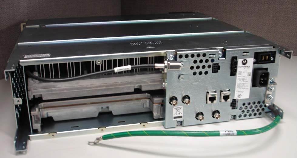
Click to zoom
Application Details
- Equipment Class
- TNB - Licensed Non-Broadcast Station Transmitter
- Date of Grant
- May 29, 2013
- Application Purpose
- Original Equipment
- Date of Application
- May 29, 2013
- Equipment Note
- Non-Broadcast Transmitter
- Frequency Range
- 775.00000000 - 776.00000000
- Company
- Motorola Solutions, Inc.
- Country
- United States
Documents & Files
Document Text
Text extracted from the exhibit documents filed with the FCC. Open a document above to read the original.
Users Manual
APPLICANT: MOTOROLA SOLUTIONS EQUIPMENT TYPE: ABZ89FC5812B 109AB-5812B EXHIBIT D User / Operational Manual Operational or User’s Manual The manual should include instruction, installation, operator, or technical manuals with required ‘information to the users’. This manual should include a statement that cautions the user that changes or modifications not expressly approved by the party responsible for compliance could void the user’s authority to operate the equipment. The manual shall include RF Hazard warning statements, if applicable. Draft copy of some of the manual information has been assembled and has been included as part of this filing package. Upon request, published and/or printed manuals will be sent to the commission and/or telecommunication certification body (TCB). All of the descriptions, block diagrams, and schematics that are included in this filing package are current as of the package submittal date. EXHIBIT DESCRIPTION D1-1 Manual Front Matter (Draft) D1-2 Specifications (Draft) D1-3 Field Replaceable Units and Orderable Parts (Draft) D1-4 Tune-Up Procedure D1-5 Racking Configurations D1-6 Functional Description / Operation of Modules (Draft) APPLICANT: MOTOROLA SOLUTIONS EQUIPMENT TYPE: ABZ89FC5812B 109AB-5812B EXHIBIT D1-1 User / Operational Manual Manual Front Matter A copy of the multi-lingual lingual document, “General Safety Precautions and Installation Standards and Guidelines”, is included with each base radio shipped. This document gives general safety precautions pertaining to installation and RF exposure. The English and French sections are included, below, as part of this filing package. English: General Safety Precautions and Installation Standards and Guidelines WARNING: For safe installation, operation, service and repair of this equipment, follow the safety precautions and instructions described below, as well as any additional safety information in Motorola’s product service and installation manuals and the Motorola R56 Standards and Guidelines for Communications Sites manual (6881089E50). To obtain copies of these materials, please contact Motorola as directed at the end of this document. After installation, these instructions should be retained and readily available for any person operating or servicing this base station or working near it. Failure to follow these safety precautions and instructions could result in serious injury or property damage. The installation process requires preparation and knowledge of the site before installation begins. Review installation procedures and precautions in the Motorola R56 manual before performing any site or component installation. Personnel must use safe work practices and good judgment, and always follow applicable safety procedures, such as requirements of the Occupational Safety and Health Administration (OSHA), the National Electrical Code (NEC), and local codes. The following are additional general safety precautions that must be observed: • To continue compliance with any applicable regulations and maintain the safety of this equipment, do not install substitute parts or perform any unauthorized modifications. • All equipment must be serviced by Motorola trained personnel. • If troubleshooting the equipment while the power is on, be aware of the live circuits which could contain hazardous voltage. • Do not operate the radio transmitters unless all RF connectors are secure and all connectors are properly terminated. • All equipment must be properly grounded in accordance with the Motorola R56 and specified installation instructions for safe operation. • Slots and openings in the cabinet are provided for ventilation. Do not block or cover openings that protect the devices from overheating. • Some equipment components can become extremely hot during operation. Turn off all power to the equipment and wait until sufficiently cool before touching. • Maintain emergency first aid kits at the site. • Never store combustible materials in or near equipment racks. The combination of combustible material, heat and electrical energy increases the risk of a fire hazard. • Equipment shall be installed in site that meets the requirements of a “restricted access location”, per (UL60950-1 & EN60950-1), which is defined as follows: “Access can only be gained by service persons or by users who have been instructed about the reasons for the restrictions applied to the location and about any precautions that shall be taken; and access is through the use of a tool or lock and key, or other means of security, and is controlled by the authority responsible for the location.” • Burn hazard. The metal housing of the product may become extremely hot. Use caution when working around the equipment. • RF energy burn hazard. Disconnect power in the cabinet to prevent injury while disconnecting and connecting antennas. • Shock hazard. The outer shields of all TX and RX cables must be grounded per Motorola R56 manual. • Shock hazard. DC input voltage shall be no higher than 60VDC. This maximum voltag e shall include consideration of the battery charging “float voltage” associated with the intended supply system, regardless of the marked power rating of the equipment. • All TX and RX RF cables shall be connected to a surge protection device according to Motorola R56 manual. Do not connect TX and RX RF cables directly to an outside antenna. • Compliance with National and International standards and guidelines for human exposure to Electromagnetic Energy (EME) at Transmitter Antenna sites generally requires that persons having access to a site shall be aware of the potential for exposure to EME and can exercise control of exposure by appropriate means, such as adhering to warning sign instructions. See this installation manual and Appendix A of Motorola R56. Refer to product specific manuals for detailed safety and installation instructions. Manuals can be obtained with product orders, downloaded from https://businessonline.motorola.com…
Text truncated - open the document above for the full version.
External Photos
APPLICANT: MOTOROLA SOLUTIONS EQUIPMENT TYPE: ABZ89FC5812B 109AB-5812B EXHIBIT C1-1 Photographs of the Device External Front View of Base Radio APPLICANT: MOTOROLA SOLUTIONS EQUIPMENT TYPE: ABZ89FC5812B 109AB-5812B EXHIBIT C1-2 Photographs of the Device External Front View of Base Radio, Front Panel Removed APPLICANT: MOTOROLA SOLUTIONS EQUIPMENT TYPE: ABZ89FC5812B 109AB-5812B EXHIBIT C1-3 Photographs of the Device External Front View of Base Radio, Alternate Racking of Base Radio in ‘GTR 8000 Expandable Site Sub-system’ Configuration APPLICANT: MOTOROLA SOLUTIONS EQUIPMENT TYPE: ABZ89FC5812B 109AB-5812B EXHIBIT C2-1 Photographs of the Device External Back View of Base Radio
ID Label/Location Info
APPLICANT: MOTOROLA SOLUTIONS EQUIPMENT TYPE: ABZ89FC5812B 109AB-5812B EXHIBIT A1 Equipment Label FCC / IC Identification Numbers The FCC Identifier (FCC ID) is made up of the Grantee Code, supplied by the FCC, and an Equipment Product Code. This equipment product code may be to 14 characters in length, and is assigned by the grantee (applicant). The Grantee Code for this product is ABZ The Equipment Product Code for this product is 89FC5812B The entire FCC ID number is ABZ89FC5812B The Industry Canada (IC) identification consists of the certification / registration number as well as the IC model number. The certification / registration number is made up of Company Number (CN) assigned by Industry Canada, and the Unique Product Number (UPN) assigned by Motorola. The IC model number is the unique model number of the radio assigned by Motorola. The Company Number is 109AB The Certification / Registration Number for this product is 109AB-5812B The IC Model Number is T7039-700B APPLICANT: MOTOROLA SOLUTIONS EQUIPMENT TYPE: ABZ89FC5812B 109AB-5812B EXHIBIT A2-1 Equipment Label FCC / IC Identification Label A representative image of the FCC / IC Identification label is shown below. This label is generated as part of the standard manufacturing process and is printed in the factory. Much of the information that is on the label, such as serial number, model number, etc. is driven by the ordering process and is unique per customer order. Serial No: F.O. Page No: Item No: Model No. T7039A TX FCC ID: A BZ89FC5812B RX FCC ID: ABZ89FR5811B IC: 109AB-5812B IC Model No: T7039-700B This device complies with Part 15 of the FCC Rules. Operation is subject to the condition that this device does not cause harmful interference. 90-230V 10A Max. 50/60 Hz 48V 18A US: ABZNINANT7039 Assembled in USA I.T.E. 31 NH FCC / IC Identification Label APPLICANT: MOTOROLA SOLUTIONS EQUIPMENT TYPE: ABZ89FC5812B 109AB-5812B EXHIBIT A2-2 Equipment Label FCC / IC ID Label The location of the identification label is on the back of the radio, as shown in the photograph below. Location of FCC/ IC Identification Label
Internal Photos
APPLICANT: MOTOROLA SOLUTIONS EQUIPMENT TYPE: ABZ89FC5812B 109AB-5812B EXHIBIT C3-1.1 Photographs of the Device Internal Front View – Transceiver Module Transceiver Module without the Transceiver Option Card (TOC) Transceiver Module with the Transceiver Option Card (TOC) Installed Front View of Base Radio Showing Transceiver Module with TOC Installed and Identifying Connections APPLICANT: MOTOROLA SOLUTIONS EQUIPMENT TYPE: ABZ89FC5812B 109AB-5812B EXHIBIT C3-1.2 Photographs of the Device Internal Front View – Transceiver Module Circuit Board Top View APPLICANT: MOTOROLA SOLUTIONS EQUIPMENT TYPE: ABZ89FC5812B 109AB-5812B EXHIBIT C3-1.3 Photographs of the Device Internal Front View – Transceiver Module, Control Section APPLICANT: MOTOROLA SOLUTIONS EQUIPMENT TYPE: ABZ89FC5812B 109AB-5812B EXHIBIT C3-1.4 Photographs of the Device Internal Front View – Transceiver Module, Exciter Section APPLICANT: MOTOROLA SOLUTIONS EQUIPMENT TYPE: ABZ89FC5812B 109AB-5812B EXHIBIT C3-1.5 Photographs of the Device Internal Front View – Transceiver Module, Receiver Section APPLICANT: MOTOROLA SOLUTIONS EQUIPMENT TYPE: ABZ89FC5812B 109AB-5812B EXHIBIT C3-2 Photographs of the Device Internal Front View – Power Amplifier Module, Cover Removed APPLICANT: MOTOROLA SOLUTIONS EQUIPMENT TYPE: ABZ89FC5812B 109AB-5812B EXHIBIT C3-3.1 Photographs of the Device Internal Front View – Power Supply Module APPLICANT: MOTOROLA SOLUTIONS EQUIPMENT TYPE: ABZ89FC5812B 109AB-5812B EXHIBIT C3-3.2 Photographs of the Device Internal Front View – Power Supply Module, Circuit Boards, Top View APPLICANT: MOTOROLA SOLUTIONS EQUIPMENT TYPE: ABZ89FC5812B 109AB-5812B EXHIBIT C3-4 Photographs of the Device Internal Front View – Backplane APPLICANT: MOTOROLA SOLUTIONS EQUIPMENT TYPE: ABZ89FC5812B 109AB-5812B EXHIBIT C3-5 Photographs of the Device Internal Front View – Transceiver Option Card (TOC) APPLICANT: MOTOROLA SOLUTIONS EQUIPMENT TYPE: ABZ89FC5812B 109AB-5812B EXHIBIT C4-1 Photographs of the Device Internal Back View – Transceiver Module APPLICANT: MOTOROLA SOLUTIONS EQUIPMENT TYPE: ABZ89FC5812B 109AB-5812B EXHIBIT C4-2 Photographs of the Device Internal Back View – Power Amplifier Module APPLICANT: MOTOROLA SOLUTIONS EQUIPMENT TYPE: ABZ89FC5812B 109AB-5812B EXHIBIT C4-3 Photographs of the Device Internal Back View – Power Supply Module, Circuit Boards, Back View APPLICANT: MOTOROLA SOLUTIONS EQUIPMENT TYPE: ABZ89FC5812B 109AB-5812B EXHIBIT C4-4 Photographs of the Device Internal Back View – Backplane APPLICANT: MOTOROLA SOLUTIONS EQUIPMENT TYPE: ABZ89FC5812B 109AB-5812B EXHIBIT C4-5 Photographs of the Device Internal Back View – Transceiver Option Card (TOC)
Parts List/Tune Up Info
APPLICANT: MOTOROLA SOLUTIONS EQUIPMENT TYPE: ABZ89FC5812B 109AB-5812B EXHIBIT D1-4 User / Operational Manual Tune-Up Procedure There is no field tune-up procedure. All adjustments are software controlled and are pre-set at the factory. Certain station operating parameters can be changed via man-machine interface (MMI) commands, within predetermined limits. Examples include transmit / receive operating frequencies and transmitter power level.
Test Report
APPLICANT: MOTOROLA SOLUTIONS EQUIPMENT TYPE: ABZ89FC5812B 109AB-5812B EXHIBIT E Report on Test Measurements Measurements Report The measurement report shows compliance information against the pertinent technical standards. Each parameter is measured generally at the low end, middle, and at the high end of the applicable frequency band. Each section of the report contains either verbiage or graphs which show compliance to applicable standards as required, explains testing method used, and indicates what the applicable specification is. A list of test equipment and certification signoff page are included at the end of the measurement report. SUBMITTED MEASURED DATA -- INDEX EXHIBIT DESCRIPTION E1-1 RF Output-Data E1-2 Adjacent Channel Power: Setup, Specifications, and Index (H-DQPSK / LSM, C4FM, HPD) E1-2.1 ACP Results 400 kHz for H-DQPSK / LSM, C4FM, HPD E1-2.2, 3, 4 ACP Results >400 kHz for H-DQPSK / LSM, Low End / Middle / High End of band E1-2.5, 6, 7 ACP Results >400 kHz for C4FM, Low End / Middle / High End of band E1-2.8, 9, 10 ACP Results >400 kHz for HPD, Low End / Middle / High End of band E1-3 Conducted Spurious Emissions: Setup, Specifications, and Index E1-3.1 LSM Conducted Spurious Harmonic Emissions, Power 100 Watts (Average) E1-3.2 LSM Conducted Spurious Harmonic Emissions, Power 2 Watts (Average) E1-3.3 C4FM Conducted Spurious Harmonic Emissions, Power 100 Watts E1-3.4 C4FM Conducted Spurious Harmonic Emissions, Power 2 Watts E1-3.5 HPD Conducted Spurious Harmonic Emissions, Power 50 Watts (Average) E1-3.6 HPD Conducted Spurious Harmonic Emissions, Power 2 Watts (Average) E1-4 Radiated Spurious Emissions: Setup, Specifications, and Index E1-4.1 LSM Conducted Spurious Harmonic Emissions, Power 100 Watts (Average) E1-4.2 LSM Conducted Spurious Harmonic Emissions, Power 2 Watts (Average) E1-4.3 C4FM Conducted Spurious Harmonic Emissions, Power 100 Watts E1-4.4 C4FM Conducted Spurious Harmonic Emissions, Power 2 Watts E1-4.5 HPD Conducted Spurious Harmonic Emissions, Power 50 Watts (Average) E1-4.6 HPD Conducted Spurious Harmonic Emissions, Power 2 Watts (Average) E1-5 Frequency Stability: Setup, Specifications, and Index E1-5.1 Frequency Stability Vs Temperature E1-5.2 Frequency Stability Vs Voltage E1-6 Protection of the 1559 – 1610 MHz Frequency Band: Setup, Specifications, and Index E1-6.1 LSM out of band emissions, Power 100 Watts (Average) E1-11 Test Equipment Used E1-12 Statement of Certification APPLICANT: MOTOROLA SOLUTIONS EQUIPMENT TYPE: ABZ89FC5812B 109AB-5812B EXHIBIT E1-1 Report on Test Measurements RF Power Output Data The RF power output was measured with the indicated voltage applied to and current into the final RF amplifying device. The DC current indicated is the total for the final RF amplifier stage, consisting of six parallel power transistors. High Performance Data Modulation Mode: 768 MHz 772 MHz 776 MHz Measured RF output 50 50 50 Watts, Average DC Voltage, final RF amplifier stage/stages 24.7 24.7 24.7 Volts DC Current, final RF amplifier stage/stages 10.1 10.1 10.0 Amperes Input power for final RF amplifying device(s) 249 247 247 Watts Primary Radio Input Supply Voltage 120 120 120 Volts AC Minimum Measured RF output 2 2 2 Watts, Average Normal DC Voltage 19.0 19.0 19.0 Volts Normal DC Current 2.9 3.0 3.0 Amperes Input power for final RF amplifying device(s) 55 57 57 Watts Primary Radio Input Supply Voltage 120 120 120 Volts AC Linear Simulcast Modulation Mode: 768 MHz 772 MHz 776 MHz Measured RF output 100 100 100 Watts, Average DC Voltage, final RF amplifier stage/stages 23.7 23.7 23.7 Volts DC Current, final RF amplifier stage/stages 12.1 12.1 12.0 Amperes Input power for final RF amplifying device(s) 287 287 284 Watts Primary Radio Input Supply Voltage 120 120 120 Volts AC Minimum Measured RF output 2 2 2 Watts, Average Normal DC Voltage 19.0 19.0 19.0 Volts Normal DC Current 2.5 2.5 2.5 Amperes Input power for final RF amplifying device(s) 48 48 48 Watts Primary Radio Input Supply Voltage 120 120 120 Volts AC Compatible 4-Level Frequency Modulation Mode: 768 MHz 772 MHz 776 MHz Measured RF output 100 100 100 Watts DC Voltage, final RF amplifier stage/stages 19.5 19.5 19.5 Volts DC Current, final RF amplifier stage/stages 13.3 13.3 13.2 Amperes Input power for final RF amplifying device(s) 259 259 257 Watts Primary Radio Input Supply Voltage 120 120 120 Volts AC Minimum Measured RF output 2 2 2 Watts, Average Normal DC Voltage 19.0 19.0 19.0 Volts Normal DC Current 2.6 2.6 2.6 Amperes Input power for final RF amplifying device(s) 49 49 49 Watts Primary Radio Input Supply Voltage 120 120 120 Volts AC APPLICANT: MOTOROLA SOLUTIONS EQUIPMENT TYPE: ABZ89FC5812B 109AB-5812B EXHIBIT E1-2 (Sheet 1 of 2) Report on Test Measurements Adjacent Channel Power (ACP) Requirements The transmitter can utilize various modulation modes as determined by customer requirements, channel usage, and system configuration as described in Exhibit B. These modulations are: High Performance Data (HPD) which operates at 50 Watts (average) in 25 kHz channels; linear modulations which operate at 100 Watts (average) in 12.5 kHz channels, and Compatible 4-Level Frequency Modulation (C4FM) which is a non linear modulation and operates in 12.k kHz channels at 100 Watts. The two types of linear modulations are similar, Linear Simulcast Modulation (LSM) is for FDMA applications, and H-DQPSK is for TDMA applications. For purposes of the ACP performance present in this exhibit, both of these linear modulations perform similarly and data from only one of them is presented. All of the following charts reference the following setup and specification requirements for the modes summarized as follows: Modulation Type: HPD LSM / H-DQPSK C4FM Channelization: 25 kHz 12.5 kHz 12.5 kHz Power Setting: 50 Watts, Average 100 Watts, Average 100 Watts Specification Requirement Limits: FCC §90.543, §27.53 and IC RSS-119 section 5.8.9 § 90.543 Emission limits: For operation in the 769-775 MHz Band § 2…
Text truncated - open the document above for the full version.
Contact Information
Applicant
Matthew Nawrocki
Non-Technical Contact
Motorola Solutions, Inc.Greg Alms
[email protected]8475768450
Technical Specifications
| # | Rule Parts | Frequency Range | Power Output | Emission | Tolerance |
|---|---|---|---|---|---|
| 2 | 27 | 775 MHz - 776 MHz | 50 W | 17K7D7D | 0.1 ppm |
Other Applications from Motorola Solutions, Inc.

ABZ89FT4940
Aug 06, 2026Non Broadcast Transmitter
Equipment Class
TNB - Licensed Non-Broadcast Station TransmitterABZ89FT4950
Jun 25, 2026Non-Broadcast Transmitter
Equipment Class
TNB - Licensed Non-Broadcast Station TransmitterABZ89FT5901
Jun 20, 2024Non Broadcast Transmitter
Equipment Class
TNB - Licensed Non-Broadcast Station Transmitter
ABZ99FT5101B
May 02, 2023Non Broadcast Transmitter
Equipment Class
PCB - PCS Licensed Transmitter
ABZ99FT3095B
Mar 26, 2023Non Broadcast Transmitter
Equipment Class
TNB - Licensed Non-Broadcast Station Transmitter