ABZ89FT7608ML900 Notebook PC w/ CDMA Modem
Motorola Solutions, Inc.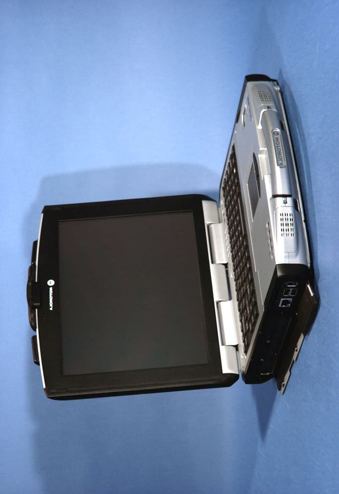
Click to zoom
Application Details
- Equipment Class
- PCB - PCS Licensed Transmitter
- Date of Grant
- Mar 31, 2004
- Application Purpose
- Original Equipment
- Date of Application
- Mar 31, 2004
- Equipment Note
- ML900 Notebook PC w/ CDMA Modem
- Frequency Range
- 1851.25000000 - 1908.75000000
- Company
- Motorola Solutions, Inc.
- Country
- United States
Documents & Files
Document Text
Text extracted from the exhibit documents filed with the FCC. Open a document above to read the original.
Users Manual
i Mobile Laptop 900™ Model L3393, L3394 Motorola, Inc. Commercial, Government and Industrial Solutions Sector All rights reserved Owner’s Manual R02 Part No.: DDN 7415 TRADEMARKS All brand and product names are trademarks or registered trademarks of their respective companies. NOTE Information in this manual is subject to change without notice. Regulations Information Class B Regulations USA Federal Communications Commission Radio Frequency Interference Statement NOTE: This equipment has been tested and found to comply with the limits for a Class B digital device pursuant to Part 15 of the FCC Rules. These limits are designed to provide reasonable protection against harmful interference in a residential installation. This equipment generates, uses, and can radiate radio frequency energy and, if not installed and used in accordance with the instructions, may cause harmful interference to radio communications. However, there is no guarantee that interference will not occur in a particular installation. If this equipment does cause harmful interference to radio or television reception, which can be determined by turning the equipment off and on, the user is encouraged to try to correct the interference by one or more of the following measures: −Reorient or relocate the receiving antenna. −Increase the separation between the equipment and receiver. −Connect the equipment into an outlet on a circuit different from that to which the receiver is connected. −Consult the dealer or an experienced radio/TV technician for help. Any changes or modifications not expressly approved by the manufacturer could void the user’s authority to operate the equipment. Please note: The use of a non-shielded interface cable with this equipment is prohibited. Wireless LAN Module Statement FCC CAUTION: This device complies with Part 15 of the FCC Rules. Operation is subject to the following two conditions: (1) this device may not cause harmful interference, and (2) this device must accept any interference received, including interference that may cause undesired operation. FCC RF Radiation Exposure Statement This equipment complies with FCC RF radiation exposure limits set forth for an uncontrolled environment. This equipment should be installed and operated with a minimum distance of 20 cm between the radiator and your body. To assure continued compliance (example – use only shielded interface cables when connecting to computer or peripheral devices), any changes or modifications not expressly approved by the party responsible for compliance could void the user's authority to operate this equipment. Canada Canadian Department of Communications Radio Interference Regulations Class B Compliance Notice This digital apparatus does not exceed the Class B limits for radio noise emissions from digital apparatus set out in the Radio Interference Regulations of the Canadian Department of Communications. Le présent appareil numérique n’ émet pas de bruits radioélectriques dépassant les limites applicables aux appareils numériques de la classe B prescrites dans le Règlement sur le brouillage radioélectrique édicté par le ministère des Communications du Canada. SAFE USAGE NOTIFICATION: For reason of personal safety and optimal radio performance, Motorola has designed the ML900 with an intended purpose and position of use either in a secured vehicle docking station or on the top of an office desk. Motorola strongly recommends using this product in a vehicle only when it is physically-secured in a lock or assured-stationary location as failure to do so may cause the product to cause harm in accidents or other conditions. Similarly, Motorola strongly recommends that the unit not be situated for a prolonged period in an a position that places the antennas directly against the human body ( for example, by “tucking” an operational, radio-equipped unit under one’ s arm). NOTE: The radio modems in the ML900 may continue to transmit and receive signals even while the laptop is in a closed position. Failure to follow any part of this notification could cause degraded radio performance or harm to the user”. About the Battery Caution Texts Concerning Lithium Batteries DANISH ADVARSEL! Lithiumbatteri – Eksplosionsfare ved fejlagtig håndtering. Udskiftning må kun ske med batteri af samme fabrikat og type. Levér det brugte batteri tilbage til leverandøren. NORWEGIAN ADVARSEL: Eksplosjonsfare ved feilaktig skifte av batteri. Benytt samme batteritype eller en tilsvarende type anbefalt av apparatfabrikanten. Brukte batterier kasseres i henhold til fabrikantens instruksjoner. SWEDISH VARNING: Explosionsfara vid felaktigt batteribyte. Använd samma batterityp eller en ekvivalent typ som rekommenderas av apparattillverkaren. Kassera använt batteri enligt fabrikantens instruktion. FINNISH VAROITUS: Paristo voi räjähtää, jos se on virheellisesti asennettu. Vaihda paristo ainoastaan valmistajan suosittelemaan tyyppiin. Hävitä käytetty paristo valmistajan ohjeiden mukaisesti. ENGLISH CAUTION: Danger of explosion if battery is incorrectly replaced. Replace only with the same or equivalent type recommended by the equipment manufacturer. Discard used batteries according to manufacturer's instructions. DEUTSCH VORSICHT: Explosionsgefahr bei unsachgemäßem Austausch der Batterie. Ersatz nur durch denselben oder einen vom Hersteller empfohlenen gleich-wertigen Typ. Entsorgung gebrauchter Batterien nach Angaben des Herstellers. FRENCH ATTENTION: II y a danger d’explosion s’il y a remplacement incorrect de la batterie. Remplacer uniquement avec une batterie du même type ou d’un type équivalent recommandé par le constructeur. Mettre au rebut les batteries usagées conformément aux instructions du fabricant. Attention (for USA Users) The product that you have purchased contains a rechargeable battery. The battery is recyclable. At the end of its useful life, under various state and local laws, it may be illegal to dispose of this battery into the municipal waste s…
Text truncated - open the document above for the full version.
Users Manual
3-10Managing Power CHAPTER 4 Expanding Your Computer You can expand the capabilities of your computer by connecting other peripheral devices. When using a device, be sure to read the instructions accompanying the device together with the relevant section in this chapter. This chapter gives guidelines on installing and using these devices: l External monitor l USB device l Serial device l IR device l Bluetooth-capable device l IEEE 1394 device l Video capture device 4-2Expanding Your Computer Connecting an External Monitor If you want the benefits of a larger display screen with higher resolution, you can connect an external CRT monitor that supports the DVI interface to your computer. Follow this procedure to connect an external monitor: 1. Make sure that the computer is not turned on. 2. Plug the DVI adapter to the computer’s DVI-I port. 3. Plug the signal connector to the DVI adapter. 4. Plug the monitor’s power cord into an electrical outlet. 5. To use the monitor, turn on the monitor before turning on the computer. 6. The monitor should respond by default. If not, you can switch the display to the monitor or to both (simultaneous display), or to multi- display by pressing Fn + F9 . 7. You can change display settings through your operating system (Display Properties in Windows). See your operating system documentation or online help for specific information. CAUTION: Do not disconnect the external monitor while the computer is in Standby mode or Hibernation mode. If no external monitor is connected when the computer resumes, the LCD remains blank and the output is not displayed. Expanding Your Computer4-3 Connecting a USB Device NOTE: To take advantage of the USB 2.0 feature, the USB 2.0 driver supplied with your computer must be installed (see chapter 6). Your computer has four USB ports that supports transfer rates up to 12 MB/s for USB 1.1 devices and 480 MB/s for USB 2.0 devices, such as digital camera, scanner, printer, modem, and mouse. USB is specified to be an industry standard extension to the PC architecture. It supports “Plug-and-Play” technology so you can install and remove USB devices without turning off the computer. With its multiple connection capability, up to 127 devices can be connected in a daisy-chain configuration. In addition, you can use a USB hub that converts a single USB connector into multiple ports where USB devices can be connected. To connect a USB device, simply plug the device cable to one of the USB ports. 4-4Expanding Your Computer Connecting a Serial Device Your computer has a serial port for connecting a serial device such as an external modem. Follow this procedure to connect a serial device: 1. Make sure the “COM1 Ports” item is set properly in the SCU program. (See “Components Menu” in Chapter 5 for information.) 2. Make sure the computer is not turned on. 3. Plug the device cable to the serial port on the rear of the computer. 4. Turn on the computer. NOTE: Portable modems that derive power through the serial port cannot be used with the computer. Instead, use a modem that is powered by its own internal battery or external AC power. Expanding Your Computer4-5 Connecting an IR Device Your computer has an IR (infrared) port for connecting an infrared- equipped device wirelessly such as another computer, printer, or PDA (Personal Digital Assistant). Follow this procedure to connect an IR device: 1. Under Windows, make sure that the IrDA Fast Infrared Port is set to HP HSDL-2300/3600. (See “How to Use the Driver CD” in Chapter 6 for information.) 2. Make sure that the “COM Ports” and its “Mode Setting For COM2” items are set properly in the SCU program. (See “Components Menu” in Chapter 5 for information.) 3. When using the IR port: Place the transmitting device where its IR port faces the IR port of your computer within the effective range − within ±20-degrees vertical angle and within ±20-degrees horizontal angle at no greater than 0.8~1.0 meter distance. Place the receiving device where the IR port of your computer faces its IR port within the effective range − within ±15-degrees vertical angle and within ±15-degrees horizontal angle at no greater than 0.8~1.0 meter distance. 4. To take advantage of the IR communications, you need a third party software. NOTES: During infrared communication, take note of the following: l Do not move the computer and IR device. l Do not enter Standby mode. l Do not use a cell phone or another IR device near the computer. l Avoid strong light such as sunlight or fluorescent light. l Disable the screen saver. 4-6Expanding Your Computer Expanding Your Computer4-7 Connecting a Bluetooth-compliant Device (option) NOTE: To take advantage of the Bluetooth feature, the Bluetooth driver supplied with your computer must be installed (see chapter 6 for details). Your computer has a Bluetooth port for connecting a Bluetooth- compliant device wirelessly. Bluetooth is a short-range wireless communications technology. Devices with Bluetooth capabilities can exchange information over a distance of about 10 meters (30 feet) without requiring a physical connection. Unlike infrared, you do not need to line up the devices to beam information with Bluetooth. The devices only need to be within a range of about 10 meters. You can even beam information to a device in a different room, as long as it is within range. You may use Bluetooth in the following ways: • Beam Information – such as files, appointments, tasks, and contact cards, between devices that have Bluetooth capabilities. For example, if you and a co-worker each have a device with Bluetooth, you can beam items between your devices, such as files, contact cards, appointments, tasks, and so forth. • Create a dial-up modem connection – between your device and a Bluetooth phone. You can then use the Bluetooth phone as a modem. Bluetooth operates in three different modes: • On – the Bluetooth radio is turned on and you can use Bluetooth features. • Off – the Bluetooth radio is tu…
Text truncated - open the document above for the full version.
Users Manual
Installing Software Drivers6-5 PCI-952Shows you the instructions on installing the driver that allows you to use the optional wireless modem and GPS features to transmit information wirelessly. Upon clicking “Next Page,” the following screen appears: Drivers on the Third Page Mini-PCIShows you the instructions on installing the WLAN driver that allows you to use the internal Mini PCI WLAN card. USB-to-LANAllows you to use the network function of the computer when the optional docking station is connected. FingerprintShows you the instructions on installing the driver that allows you to use the fingerprint recognition system and its application software. 6-6Installing Software Drivers Video CaptureShows you the instructions on installing the driver that allows you to connect a video capture device through the AV input port. BluetoothAllows you to use the bluetooth port to connect to bluetooth-compliant devices. Touchscreen Driver To install the touch screen driver, perform the following: 1. Insert the driver CD into the drive. 2. Click on “Windows 2K”, then “Touchscreen” and follow the onscreen instructions to continue. 3. When finished installing, select “Yes” to reboot your system. The driver should now be loaded. 4. After the system has finished rebooting, click on the “PenMount Monitor” icon located on the taskbar to bring up the “PenMount Control Panel”. 5. Select the “Standard Calibration” folder and click on “OK.” 6. Click on “Advanced Calibration” button. 7. Click on the four sides (points) and the plus-sign “+” on the screen to calibrate your touchscreen for use on the computer. Installing Software Drivers6-7 Installing Drivers for Windows XP To set up the necessary drivers for Windows XP, click on “Windows XP” on the initial screen. The following screen appears: Drivers on the First Page To install the necessary driver, just click on the particular option and follow the onscreen instructions to continue and complete installation. ApplicationInstalls the Intel® Application Accelerator to improve performance of the storage sub-system and overall system performance. This software delivers improved performance through several ingredient technologies (components). ChipsetEnsures the full function of the following drivers. Install this main chipset driver before installing the device drivers. 6-8Installing Software Drivers VGAAllows you to select high-resolution displays with richer colors. It can drive LCD displays as well as CRT displays. AudioAllows you to take full advantage of the audio subsystem. USB 2.0Allows your system to connect to USB 2.0 devices. Upon clicking “Next Page,” the following screen appears: Drivers on the Second Page TouchpadAllows you to take full advantage of the touchpad and the scroll button features. Mini-PCIShows you the instructions on installing the WLAN driver that allows you to use the internal Mini PCI WLAN card. PCI-952Shows you the instructions on installing the driver that allows you to use the optional wireless modem and GPS features to transmit information wirelessly. Installing Software Drivers6-9 TouchscreenAllows you to use your fingers as a pointing device on the LCD screen (refer to the next section for further instructions). Upon clicking “Next Page,” the following screen appears: Drivers on the Third Page USB-to-LANAllows you to use the network function of the computer when the optional docking station is connected. FingerprintShows you the instructions on installing the driver that allows you to use the fingerprint recognition system and its application software. Video CaptureShows you the instructions on installing the driver that allows you to connect a video capture device through the AV input port. BluetoothAllows you to use the bluetooth port to connect to bluetooth-compliant devices. 6-10Installing Software Drivers Touchscreen Driver To install the touchscreen driver, perform the following: 1. Insert the driver CD into the drive. 2. Click on “Windows XP”, then “Touchscreen” and follow the onscreen instructions to continue. 3. Click on ”Start,” then “Control Panel.” Installing Software Drivers6-11 4. Click on the “Performance and Maintenance” category. 5. Click on “System.” 6-12Installing Software Drivers 6. Click on “Hardware” folder, then click on “Device Manager.” Installing Software Drivers6-13 7. Click on “? Unknown device,” then click on the “Properties” icon. 6-14Installing Software Drivers 8. Click on “Reinstall Driver.” 9. When the “Hardware Update Wizard” appears, select “Install the software automatically [Recommended],” then click on “Next.” Installing Software Drivers6-15 10. Click on “Continue Anyway.” 11. Click on “Finish.” 6-16Installing Software Drivers 12. When the “PenMount DMC9000 and DMC9100 Properties” screen appears, click on “Close” to exit the driver installation. Touchscreen Utility To install the touchscreen utility, perform the following: 1. Insert the driver CD into the drive. Installing Software Drivers6-17 2. Click on “Start”, then “Run.” 3. Enter the following directory on the driver CD: \TSRC\Setup.exe, then click on “OK.” 4. Select “Yes” to the question if this is the first time to run this setup. 5. When the “InstallShield Wizard” appears, click on “Next” to continue. 6. Select “I accept the terms in the license agreement,” then click on “Next.” 7. When the “Ready to Install the Program” screen appears, click on “Next” to continue. 8. Reboot the system. 6-18Installing Software Drivers CHAPTER 7 Caring for the Computer Taking good care of your computer will ensure a trouble-free operation and reduce the risk of damage to your computer. This chapter gives you guidelines covering these areas of maintenance: l How to protect the computer l What to note when using and storing the computer l How to clean the computer l What to note when using the battery pack l What to note when traveling with the computer 7-2Caring for the Computer Protecting the Computer To safeguard the integrity of your computer data…
Text truncated - open the document above for the full version.
External Photos
Motorola FCC ID: ABZ89FT7608 EUT Photographs © 2004 PCTEST Lab. Notebook PC w/ Motorola CDMA Modem Model: ML900 Motorola FCC ID: ABZ89FT7608 EUT Photographs © 2004 PCTEST Lab. Notebook PC w/ Motorola CDMA Modem Model: ML900 Motorola FCC ID: ABZ89FT7608 EUT Photographs © 2004 PCTEST Lab. Notebook PC w/ Motorola CDMA Modem Model: ML900 Motorola FCC ID: ABZ89FT7608 EUT Photographs © 2004 PCTEST Lab. Notebook PC w/ Motorola CDMA Modem Model: ML900
ID Label/Location Info
© 2004 PCTEST Lab FCC ID SAMPLE LABEL & LOCATION LABELLING REQUIREMENTS The Label shown shall be permanently affixed at a conspicuous location on the device and be readily visible to the user at the time of purchase. (SEE NEXT PAGE)
Internal Photos
Motorola FCC ID: ABZ89FT7608 EUT Photographs © 2004 PCTEST Lab. Notebook PC w/ Motorola CDMA Modem Model: ML900 Motorola FCC ID: ABZ89FT7608 EUT Photographs © 2004 PCTEST Lab. Notebook PC w/ Motorola CDMA Modem Model: ML900
RF Exposure Info
PCTEST MPE REPORT FCC CERTIFICATION REPORT REVIEWED BY: QUALITY MANAGER TEST REPORT S/N: 15.231217131.ABZ TEST DATES: January 5-6, 2004 EUT TYPE: Notebook PC w/ CDMA Modem FCC ID: ABZ89FT7608 PAGE 1 OF 2 © 2004 PCTEST Engineering Laboratory, Inc. RF Exposure Evaluation - Maximum Permissible Exposure (MPE) 1. Introduction This document attempts to prove the safety of radiation generated by RF devices to the human body. The limit for Maximum Permissible Exposure (MPE), specified in FCC 1.1210, is listed below. The power generated by this product is measured by a power meter. Through use of the Friis transmission formula and the maximum gain of the antenna, the distance from the product at which compliance with the MPE limit is achieved may be calculated. Alternatively, near field measurements may be performed to demonstrate compliance at a specific measurement distance. Near field probe: Wandel & Goltermann EMR-20. 2. RF Exposure Limit According to FCC 1.1310: the criteria listed in the following table shall be used to evaluate the environmental impact of human exposure to radio-frequency (RF) radiation as specified in 1.1307(b). LIMITS FOR MAXIMUM PERMISSIBLE EXPOSURE (MPE) Frequency Range (MHz) Electric Field Strength (V/m) Magnetic Field Strength (A/m) Power Density (mW/cm 2 ) Average Time (Minutes) (A) Limits For Occupational / Control Exposures 30-300 61.4 .163 1.0 6 300-1500 ... ... F/300 6 1500-100,000 ... ... 5 6 (B) Limits For General Population / Uncontrolled Exposure 30-300 27.5 .073 .2 30 300-1500 ... ... F/1500 30 1500-100,000 ... ... 1.0 30 F = Frequency in MHz 3. Friis Formula Friis transmission formula: Pd = (P out *G) / (4pr 2 ) Where: Pd = power density in mW/cm 2 (MPE limit) P out = output power to antenna in mW G = gain of antenna in linear scale p = 3.1416 r = distance between observation point and center of the radiator in cm Ref.: David K. Cheng, Field and Wave Electromagnetics, Second Edition, Page 640, Eq. (11.133) PCTEST MPE REPORT FCC CERTIFICATION REPORT REVIEWED BY: QUALITY MANAGER TEST REPORT S/N: 15.231217131.ABZ TEST DATES: January 5-6, 2004 EUT TYPE: Notebook PC w/ CDMA Modem FCC ID: ABZ89FT7608 PAGE 2 OF 2 © 2004 PCTEST Engineering Laboratory, Inc. 4. EUT Operating Condition Software provided by the client enabled the EUT to transmit and receive data at lowest, middle, and highest channels individually. 5. Climate Condition The temperature and relative humidity: 22°C and 78% RH 6. Measurement Results Channel Channel Frequency (MHz) Output Power to Antenna (mW) Power Density (mW/cm 2 ) 0383 836.49 .651 .13 Channel Channel Frequency (MHz) Output Power to Antenna (mW) Power Density (mW/cm 2 ) 0025 1851.25 .323 .06 7. Conclusion The device meets the mobile 20cm separation distance as specified in Section 2.1091 of the FCC Rules. An appropriate RF exposure compliance statement will be placed in the user’s manual.
Test Report
PCTEST PT. 22/24 REPORT FCC MEASUREMENT REPORT Reviewed By: Quality Manager Test Report S/N: 22/24.231217131.ABZ Test Dates: Jan. 5-6, 2004 EUT Type: Notebook PC W/ Motorola CDMA Modem FCC ID: ABZ89FT7608 Page 1 of 25 © 2004 PCTEST ENGINEERING LABORATORY, INC. G PCTEST Engineering Laboratory, Inc. 6660-B Dobbin Road • Columbia, MD 21045 • U.S.A. TEL (410) 290-6652 • FAX (410) 290-6654 http://www.pctestlab.com CERTIFICATE OF COMPLIANCE FCC Part 24 & 22 Certification Motorola Inc. Dates of Tests: January 5-6, 2004 1301 East Algonquin, Room 1726 Test Report S/N: 22/24.231217131.ABZ Schaumburg, IL 60196 Test Site: PCTEST Lab, Columbia MD FCC ID ABZ89FT7608 APPLICANT Motorola Inc. Classification: Licensed Portable Transmitter Worn on Body (PCT) FCC Rule Part(s): §24(E), §22H; §2 EUT Type: Notebook PC w/ Motorola CDMA Modem FCC ID: IHDT56CW1 Model: ML900 Tx Frequency Range: 824.70 – 848.31MHz (CDMA) / 1851.25MHz – 1908.75MHz (PCS CDMA) Rx Frequency Range: 869.70 – 893.31MHz (CDMA) / 1931.25MHz – 1988.75MHz (PCS CDMA) Max. RF Output Power: 0.651 W ERP CDMA (28.133 dBm) / 0.323 W EIRP PCS CDMA (25.081 dBm) Emission Designator(s): 1M25F9W (CDMA) Test Device Serial No. Identical Prototype [S/N: 2 ] This equipment has been shown to be capable of compliance with the applicable technical standards as indicated in the measurement report and was tested in accordance with the measurement procedures specified in §2.947. I attest to the accuracy of data. All measurements reported herein were performed by me or were made under my supervision and are correct to the best of my knowledge and belief. I assume full responsibility for the completeness of these measurements and vouch for the qualifications of all persons taking them. PCTEST certifies that no party to this application has been denied the FCC benefits pursuant to Section 5301 of the Anti-Drug Abuse Act of 1988, 21 U.S.C. 862. PCTEST PT. 22/24 REPORT FCC MEASUREMENT REPORT Reviewed By: Quality Manager Test Report S/N: 22/24.231217131.ABZ Test Dates: Jan. 5-6, 2004 EUT Type: Notebook PC W/ Motorola CDMA Modem FCC ID: ABZ89FT7608 Page 2 of 25 © 2004 PCTEST ENGINEERING LABORATORY, INC. TABLE OF CONTENTS ATTACHMENT A: COVER LETTER(S) ATTACHMENT B: ATTESTATION STATEMENT(S) ATTACHMENT C: TEST REPORT 1.1 SCOPE 3 2.1 INTRODUCTION 4 3.1 INSERTS 5 4.1 DESCRIPTION OF TESTS 6-9 5.1 EFFECTIVE RADIATED POWER OUTPUT 10 6.1 EQUIVALENT ISOTROPIC RADIATED POWER 11 7.1 RADIATED MEASUREMENTS 12-17 8.1 FREQUENCY STABILITY 18-21 9.1 PLOTS OF EMISSIONS 22 10.1 LIST OF TEST EQUIPMENT 23 11.1 SAMPLE CALCULATIONS 24 12.1 CONCLUSION 25 ATTACHMENT D: MOTOROLA TEST REPORT ATTACHMENT E: FCC ID LABEL / LOCATION ATTACHMENT F: TEST SETUP PHOTOGRAPHS ATTACHMENT G: EXTERNAL PHOTOGRAPHS ATTACHMENT H: INTERNAL PHOTOGRAPHS ATTACHMENT I: BLOCK DIAGRAM(S) ATTACHMENT J: SCHEMATIC DIAGRAM(S) ATTACHMENT K: OPERATIONAL / CIRCUIT DESCRIPTION ATTACHMENT L: PARTS LIST/TUNE UP PROCEDURE ATTACHMENT M: USER’S MANUAL ATTACHMENT N: MPE REPORT PCTEST PT. 22/24 REPORT FCC MEASUREMENT REPORT Reviewed By: Quality Manager Test Report S/N: 22/24.231217131.ABZ Test Dates: Jan. 5-6, 2004 EUT Type: Notebook PC W/ Motorola CDMA Modem FCC ID: ABZ89FT7608 Page 3 of 25 © 2004 PCTEST ENGINEERING LABORATORY, INC. MEASUREMENT REPORT 1.1 Scope Measurement and determination of electromagnetic emissions (EME) of radio frequency devices including intentional and/or unintentional radiators for compliance with the technical rules and regulations of the Federal Communications Commission. §2.1033 General Information Applicant Name: Motorola Inc. Address: 1301 East Algonquin, Room 1726 Schaumburg, IL 60196 • FCC ID: ABZ98FT7608 • Quantity: Quantity production is planned • Emission Designators: 1M25F9W (CDMA) • Tx Freq. Range: 824.70 – 848.31 MHz (CDMA) 1851.25 – 1908.75 MHz (PCS CDMA) • Rx Freq. Range: 869.70 – 893.31 MHz (CDMA) 1931.25 – 1988.75 MHz (PCS CDMA) • Max. Power Rating: 0.651 W ERP CDMA (28.133 dBm) 0.323 W EIRP PCS CDMA (25.081 dBm) • FCC Classification(s): Licensed Portable Transmitter Worn on Body (PCT) • Equipment (EUT) Type: Notebook PC w/ Motorola CDMA Modem FCC ID: IHDT56CW1 • Modulation(s): CDMA • Frequency Tolerance: ± 0.00025% (2.5 ppm) • FCC Rule Part(s): § 24(E), §22H • Dates of Tests: January 5-6, 2004 • Place of Tests: PCTEST Lab, Columbia, MD U.S.A. • Test Report S/N: 22/24.231217131.ABZ PCTEST PT. 22/24 REPORT FCC MEASUREMENT REPORT Reviewed By: Quality Manager Test Report S/N: 22/24.231217131.ABZ Test Dates: Jan. 5-6, 2004 EUT Type: Notebook PC W/ Motorola CDMA Modem FCC ID: ABZ89FT7608 Page 4 of 25 © 2004 PCTEST ENGINEERING LABORATORY, INC. 2.1 INTRODUCTION These measurement tests were conducted at PCTEST Engineering Laboratory, Inc. facility in New Concept Business Park, Guilford Industrial Park, Columbia, Maryland. The site address is 6660-B Dobbin Road, Columbia, MD 21045. The test site is one of the highest points in the Columbia area with an elevation of 390 feet above mean sea level. The site coordinates are 39° 11'15" N latitude and 76° 49'38" W longitude. The facility is 1.5 miles North of the FCC laboratory, and the ambient signal and ambient signal strength are approximately equal to those of the FCC laboratory. There are no FM or TV transmitters within 15 miles of the site. The detailed description of the measurement facility was found to be in compliance with the requirements of § 2.948 according to ANSI C63.4 on October 19, 1992. Measurement Procedure The radiated and spurious measurements were made outdoors at a 3-meter test range (see Figure2). The equipment under test is placed on a wooden turntable 3-meters from the receive antenna. The receive antenna height and turntable rotations were adjusted for the highest reading on the receive spectrum analyzer. A half- wave dipole was substituted in place of the EUT. This dipole antenna was driven by a signal generator and the level of the signal generator was adjusted to obtain the same receive spectrum analyzer reading. This level…
Text truncated - open the document above for the full version.
Test Report
APPLICANT: MOTOROLA INC FCC ID: IHDT56CW1 EXHIBIT 6 PERSONAL COMMUNICATIONS SECTOR PRODUCT SAFETY AND COMPLIANCE EMC LABORATORY EMC TEST REPORT Test Report Number – 9491-1 Report Date – March 6, 2003 The test results contained herein relate only to the model(s) identified. It is the manufacturer’s responsibility to assure that additional production units of this model are manufactured with identical electrical and mechanical characteristics. As the responsible EMC Engineer, I hereby declare that the equipment tested as specified in this report conforms to the requirements indicated . Signature Name: _Mark Kien_____ Title: Electrical Engineer Date : _ 03/06/03____ This report must not be reproduced, except in full, without written approval from this laboratory. THIS REPORT MUST NOT BE USED TO CLAIM PRODUCT ENDORSEMENT BY A2LA OR ANY AGENCY OF THE U.S. GOVERNMENT. A2LA Certificate Number: 1846-01 APPLICANT: MOTOROLA INC FCC ID: IHDT56CW1 Test Report Number: 9491-1EXHIBIT 6 2 Table of Contents Description Page Test Report Details4 Applicable Standards5 Summary of Testing6 General and Special Conditions6 Equipment and Cable Configurations6 Measuring Equipment and Calibration Information7 Measurement Procedures and Data RF Power Output 8 Modulation Characteristics Transmit Audio Frequency Response9 Post Limiter Filter Attenuation9 Modulation Limiting vs. Modulation Input Voltage10 Occupied Bandwidth11 AMPS Unmodulated Carrier12 AMPS Supervisory Audio Tone12 AMPS Voice13 AMPS Signaling Tone13 AMPS 10kb/s Wideband Data14 CDMA 800 Reference Plot15 CDMA 800 Mid Band Plot15 CDMA 800 Lower Band Edge16 CDMA 800 Upper Band Edge16 CDMA 1900 Reference Plot17 CDMA 1900 Mid Band Plot17 CDMA 1900 Lower Band Edge18 CDMA 1900 Upper Band Edge18 Spurious Emissions at Antenna Terminals19 AMPS Tabular and Graphical Data20 AMPS Cellular Base Station Frequency Range Plot21 CDMA 800 Tabular and Graphical Data22 CDMA 800 Cellular Base Station Frequency Range Plot23 CDMA 1900 Tabular and Graphical Data24 Field Strength of Spurious Emissions25 AMPS Tabular and Graphical Data26 CDMA 800 Tabular and Graphical Data27 CDMA 1900 Tabular and Graphical Data28 APPLICANT: MOTOROLA INC FCC ID: IHDT56CW1 Test…
Text truncated - open the document above for the full version.
Contact Information
Applicant
Matthew Nawrocki
Technical Contact
PCTEST Engineering Lab., Inc.Randy Ortanez
[email protected]410-290-6652
6660-B Dobbin Road · Columbia, Maryland · United States
Test Firm
PCTEST Engineering Laboratory, Inc.Randy Ortanez
Technical Specifications
| # | Rule Parts | Frequency Range | Power Output | Emission | Tolerance |
|---|---|---|---|---|---|
| 2 | 24E | 1.85 GHz - 1.91 GHz | 323.00 mW | 1M25F9W | 150 Hz |
Other Applications from Motorola Solutions, Inc.

ABZ89FT4940
Aug 06, 2026Non Broadcast Transmitter
Equipment Class
TNB - Licensed Non-Broadcast Station TransmitterABZ89FT4950
Jun 25, 2026Non-Broadcast Transmitter
Equipment Class
TNB - Licensed Non-Broadcast Station TransmitterABZ89FT5901
Jun 20, 2024Non Broadcast Transmitter
Equipment Class
TNB - Licensed Non-Broadcast Station Transmitter
ABZ99FT5101B
May 02, 2023Non Broadcast Transmitter
Equipment Class
PCB - PCS Licensed Transmitter
ABZ99FT3095B
Mar 26, 2023Non Broadcast Transmitter
Equipment Class
TNB - Licensed Non-Broadcast Station Transmitter