ABZ89FT76225.7GHz Fixed Wireless (ISM)
Motorola Solutions, Inc.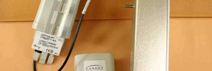
Click to zoom
Application Details
- Equipment Class
- DTS - Digital Transmission System
- Date of Grant
- Dec 28, 2006
- Application Purpose
- Original Equipment
- Date of Application
- Dec 28, 2006
- Equipment Note
- 5.7GHz Fixed Wireless (ISM)
- Frequency Range
- 5735.00000000 - 5840.00000000
- Company
- Motorola Solutions, Inc.
- Country
- United States
Documents & Files
Document Text
Text extracted from the exhibit documents filed with the FCC. Open a document above to read the original.
Users Manual
Re le ase 8 Planning Guide March 200 Through Software Re le ase 6. Issue 2, December 2006 Dra f t for Regula tory Review 127 P P L A N N I N G L A N N I N G G G U I D E U I D E Re le ase 8 Planning Guide March 200 Through Software Re le ase 6. Issue 2, December 2006 Dra f t for Regula tory Review 129 12 ENGINEERING YOUR RF COMMUNICATIONS Before diagramming network layouts, the wise course is to ◦ anticipate the correct amount of signal loss for your fade margin calculation (as defined below). ◦ recognize all permanent and transient RF signals in the environment. ◦ identify obstructions to line of sight reception. 12.1 ANTICIPATING RF SIGNAL LOSS The C/I (Carrier-to-Interference) ratio defines the strength of the intended signal relative to the collective strength of all other signals. Canopy modules typically do not require a C/I ratio greater than ◦ 3 dB or less at 10-Mbps modulation and −65 dBm for 1X operation. The C/I ratio that you achieve must be even greater as the received power approaches the nominal sensitivity (−85 dBm for 1X operation). ◦ 10 dB or less at 10-Mbps modulation and −65 dBm for 2X operation. The C/I ratio that you achieve must be even greater as the received power approaches the nominal sensitivity (−79 dBm for 2X operation). ◦ 10 dB or less at 20-Mbps modulation. 12.1.1 Understanding Attenuation An RF signal in space is attenuated by atmospheric and other effects as a function of the distance from the initial transmission point. The further a reception point is placed from the transmission point, the weaker is the received RF signal. 12.1.2 Calculating Free Space Path Loss The attenuation that distance imposes on a signal is the free space path loss. PathLossCalcPage.xls calculates free space path loss. 12.1.3 Calculating Rx Signal Level The Rx sensitivity of each module is provided at http://motorola.canopywireless.com/prod_specs.php. The determinants in Rx signal level are illustrated in Figure 37. Planning Guide Re le ase 8 130 Dra f t for Regula tory Review Issue 2, December 2006 Tx power Tx antenna gain Tx cable loss Rx antenna gain Rx cable loss Rx signal level Transmitter or Amplifier receiver or amplifier distance free space signal transmitter or amplifier Figure 37: Determinants in Rx signal level Rx signal level is calculated as follows: Rx signal level dB = Tx power − Tx cable loss + Tx antenna gain − free space path loss + Rx antenna gain − Rx cable loss NOTE: This Rx signal level calculation presumes that a clear line of sight is established between the transmitter and receiver and that no objects encroach in the Fresnel zone. 12.1.4 Calculating Fade Margin Free space path loss is a major determinant in Rx (received) signal level. Rx signal level, in turn, is a major factor in the system operating margin (fade margin), which is calculated as follows: system operating margin (fade margin) dB =Rx signal level dB − Rx sensitivity dB Thus, fade margin is the difference between strength of the received signal and the strength that the receiver requires for maintaining a reliable link. A higher fade margin is characteristic of a more reliable link. Re le ase 8 Planning Guide March 200 Through Software Re le ase 6. Issue 2, December 2006 Dra f t for Regula tory Review 131 12.2 ANALYZING THE RF ENVIRONMENT An essential element in RF network planning is the analysis of spectrum usage and the strength of the signals that occupy the spectrum you are planning to use. Regardless of how you measure and log or chart the results you find (through the Spectrum Analyzer in SM and BHS feature or by using a spectrum analyzer), you should do so ◦ at various times of day. ◦ on various days of the week. ◦ periodically into the future. As new RF neighbors move in or consumer devices in your spectrum proliferate, this will keep you aware of the dynamic possibilities for interference with your network. 12.2.1 Mapping RF Neighbor Frequencies Canopy modules allow you to ◦ use an SM or BHS (or a BHM reset to a BHS), or an AP that is temporarily transformed into an SM, as a spectrum analyzer. ◦ view a graphical display that shows power level in RSSI and dBm at 5-MHz increments throughout the frequency band range, regardless of limited selections in the Custom Radio Frequency Scan Selection List parameter of the SM. ◦ select an AP channel that minimizes interference from other RF equipment. The SM measures only the spectrum of its manufacture. So if, for example, you wish to analyze an area for both 2.4- and 5.7-GHz activity, take both a 2.4- and 5.7-GHz SM to the area. To enable this functionality, perform the following steps: CAUTION! The following procedure causes the SM to drop any active RF link. If a link is dropped when the spectrum analysis begins, the link can be re-established when either a 15-minute interval has elapsed or the spectrum analyzer feature is disabled. Procedure 2: Analyzing the spectrum 1. Predetermine a power source and interface that will work for the SM or BHS in the area you want to analyze. 2. Take the SM or BHS, power source, and interface device to the area. 3. Access the Tools web page of the SM or BHS. RESULT: The Tools page opens to its Spectrum Analyzer tab. An example of this tab is shown in Figure 143. 4. Click Enable. RESULT: The feature is enabled. 5. Click Enable again. RESULT: The system measures RSSI and dBm for each frequency in the spectrum. Planning Guide Re le ase 8 132 Dra f t for Regula tory Review Issue 2, December 2006 6. Travel to another location in the area. 7. Click Enable again. RESULT: The system provides a new measurement of RSSI and dBm for each frequency in the spectrum. NOTE: Spectrum analysis mode times out 15 minutes after the mode was invoked. 8. Repeat Steps 6 and 7 until the area has been adequately scanned and logged. =========================== end of procedure ====================== As with any other data that pertains to your business, a decision today to put the data into a retrievable database may grow in valu…
Text truncated - open the document above for the full version.
Users Manual
Re le ase 8 Installation and Configuration Guide Issue 2, December 2006 Dra f t 2 for Regula tory Review 167 I I N S T A L L A T I O N N S T A L L A T I O N A A N D N D C C O N F I G U R A T I O N O N F I G U R A T I O N G G U I D E U I D E Re le ase 8 Installation and Configuration Guide Issue 2, December 2006 Dra f t 2 for Regula tory Review 169 15 AVOIDING HAZARDS Use simple precautions to protect staff and equipment. Hazards include exposure to RF waves, lightning strikes, and power surges. This section specifically recommends actions to abate these hazards. 15.1 PREVENTING OVEREXPOSURE TO RF ENERGY To protect from overexposure to RF energy, install Canopy radios so as to provide and maintain the minimum separation distances from all persons shown in Table 40. Table 40: Exposure separation distances Canopy module Minimum separation distance from all persons Antenna of 900-MHz AP or SM 60 cm 24 in 2.4-, 5.2-, 5.4-, or 5.7-GHz radio with no reflector 20 cm 8 in 2.4-, 5.4-, or 5.7-GHz radio with a reflector 1.5 m 60 in (5 ft) Antenna of connectorized 5.7 GHz AP 20 cm 8 in At these and greater separation distances, the power density from the RF field is below generally accepted limits for the general population. − NOTE: These are conservative distances that include compliance margins. In the case of the reflector, the distance is even more conservative because the equation used models the reflector as a point source and ignores its physical dimensions. 15.1.1 Details of Calculations for Separation Distances and Power Compliance Margins Limits and guidelines for RF exposure come from: ◦ US FCC limits for the general population. See the FCC web site at http://www.fcc.gov, and the policies, guidelines, and requirements in Part 1 of Title 47 of the Code of Federal Regulations, as well as the guidelines and suggestions for evaluating compliance in FCC OET Bulletin 65. ◦ Health Canada limits for the general population. See the Health Canada web site at http://www.hc-sc.gc.ca/rpb and Safety Code 6. ◦ ICNIRP (International Commission on Non-Ionizing Radiation Protection) guidelines for the general public. See the ICNIRP web site at http://www.icnirp.de/ and Guidelines for Limiting Exposure to Time-Varying Electric, Magnetic, and Electromagnetic Fields. Installation and Configuration Guide Re le ase 8 170 Dra f t 2 for Regula tory Review Issue 2, December 2006 The applicable power density exposure limits from the documents referenced above are ◦ 6 W/m 2 for RF energy in the 900-MHz frequency band in the US and Canada. ◦ 10 W/m 2 for RF energy in the 2.4-, 5.2-, 5.4-, and 5.7-GHz frequency bands. Peak power density in the far field of a radio frequency point source is calculated as follows: where S = power density in W/m 2 P = RMS transmit power capability of the radio, in W G = total Tx gain as a factor, converted from dB d = distance from point source, in m Rearranging terms to solve for distance yields P G . 4 p d S = Calculated Distances and Power Compliance Margins Table 41 shows calculated minimum separation distances d, recommended distances and resulting power compliance margins for each frequency band and antenna combination. Table 41: Calculated distances and power compliance margins Variable Frequency Band Antenna P G S d (Calcu- lated) Recom- mended Distance Power Compliance Margin 900 MHz external 0.4 W (26 dBm) 10.0 (10 dB) 6 W/m 2 0.23 m 60 cm (24 in) 7 internal 0.34 W (25 dBm) 6.3 (8 dB) 10 W/m 2 0.13 m 20 cm (8 in) 2.3 2.4 GHz internal plus reflector 0.34 W (25 dBm) 79.4 (19 dB) 10 W/m 2 0.46 m 1.5 m (5 ft) 10 internal 0.2 W (23 dBm) 5.0 (7 dB) 10 W/m 2 0.09 m 20 cm (8 in) 5 5.2 GHz internal plus reflector 0.0032 W (5 dBm) 316 (25 dB) 10 W/m 2 0.09 m 1.5 m (5 ft) 280 internal 0.2 W (23 dBm) 5.0 (7 dB) 10 W/m 2 0.09 m 20 cm (8 in) 5 5.4 GHz internal plus reflector 0.0032 W (5 dBm) 316 (25 dB) 10 W/m 2 0.09 m 1.5 m (5 ft) 280 S = P • G 4 π d 2 Re le ase 8 Installation and Configuration Guide Issue 2, December 2006 Dra f t 2 for Regula tory Review 171 Variable Frequency Band Antenna P G S d (Calcu- lated) Recom- mended Distance Power Compliance Margin internal 0.2 W (23 dBm) 5.0 (7 dB) 10 W/m 2 0.09 m 20 cm (8 in) 5 internal plus reflector 0.2 W (23 dBm) 316 (25 dB) 10 W/m 2 0.71 m 1.5 m (5 ft) 4.5 5.7 GHz external 0.125 W (21 dBm) 31.6 (15 dB) 10 W/m 2 0.18 m 20 cm (8 in) 1.27 15.2 GROUNDING CANOPY EQUIPMENT Effective lightning protection diverts lightning current safely to ground, Protective Earth (PE) . It neither attracts nor prevents lightning strikes. WARNING! Lightning damage is not covered under the Canopy warranty. The recommendations in Canopy guides give the installer the knowledge to protect the installation from the harmful effects of ESD and lightning. These recommendation must be thoroughly and correctly performed. However, complete protection is neither implied or possible. 15.2.1 Grounding Infrastructure Equipment To protect both your staff and your infrastructure equipment, implement lightning protection as follows: ◦ Observe all local and national codes that apply to grounding for lightning protection. ◦ Before you install your Canopy modules, perform the following steps: − Engage a grounding professional if you need to do so. − Install lightning arrestors to transport lightning strikes away from equipment. For example, install a lightning rod on a tower leg other than the leg to which you mount your module. − Connect your lightning rod to ground. − Use a Canopy 300SS Surge Suppressor (or Transtector ALPU-ORTs for OFDM BH installations) on the Ethernet cable where the cable enters any structure. (Instructions for installing a Canopy 300SS Surge Suppressor are provided in Procedure 28 on Page 346.) ◦ Install your modules at least 2 feet (0.6 meters) below the tallest point on the tower, pole, or roof. Installation and Configuration Guide Re le ase 8 172 Dra f t 2 for Regula tory Review Issue 2, December 2006 15.2.2 Grounding Canopy 30/60- and 150/300-Mbps Backhaul M…
Text truncated - open the document above for the full version.
Users Manual
Re le ase 8 Installation and Configuration Guide Issue 2, December 2006 Dra f t for Regula tory Review 217 Perform the following procedure to set up the CMMmicro. IMPORTANT! Start with the 24-V DC power converter unconnected to AC. Procedure 17: Setting up a CMMmicro 1. Connect the converter lead whose insulation has a white stripe to +V on the CMMmicro terminal block. 2. Connect the converter lead whose insulation is solid black to -V on the CMMmicro terminal block. 3. Connect the power converter to an AC receptacle using the AC power cord. 4. Wait until the green LED labeled RDY flashes. NOTE: This should occur in less than one minute and will indicate that the CMMmicro has transitioned from booting to normal operation. 5. Observe which, if any, Ethernet ports are powered, as indicated by a lit red LED to the right of the Ethernet port. NOTE: The position of this +24-V OUT LED is shown in Figure 74 on Page 218. CAUTION! Never connect any devices other than Canopy APs and BHs to a powered port. Powered ports are indicated by a red LED to the right of the port. (See Item 7 in Figure 75 on Page 220.) A powered port has 24-V DC on Pins 7 and 8 and 24-V return on Pins 4 and 5. This can damage other networking equipment, such as a computer or a router. 6. On the 8-port Ethernet block of the CMMmicro, use either a straight-through or crossover Ethernet cable to connect any unpowered port (without the red LED lit) to a browser-equipped computer. NOTE: The CMMmicro auto-senses the cable type. 7. Verify these CMMmicro connections against Figure 76 on Page 220. 8. Configure the computer to use DHCP, with no proxy in your network settings. 9. Open the browser. 10. In the address bar, enter 169.254.1.1 (the default IP address of the CMMmicro). RESULT: The browser displays the CMMmicro Status page. =========================== end of procedure =========================== Installation and Configuration Guide Re le ase 8 218 Dra f t for Regula tory Review Issue 2, December 2006 Figure 74: CMMmicro door label Re le ase 8 Installation and Configuration Guide Issue 2, December 2006 Dra f t for Regula tory Review 219 1 24 V DC power connection on terminal block (+V). 2 24 V DC ground connection on terminal block (-V). 3 Ground bonding point for CMMmicro. Ground connection on terminal block, for grounding to Protective Earth (PE) . 4 Female BNC connector for connecting to coax cable from GPS antenna. 5 Status display of eight green LEDs. The left LEDs show the number of satellites visible to the CMMmicro (1, 2, ≥ 4, and ≥ 8), and the right LEDs show status: ◦ RDY (Ready) – Flashing LED indicates CMMmicro software has booted and is operational. LED continues to flash during normal operation. ◦ SYNC – Constant LED indicates CMMmicro is receiving signal from the GPS antenna and is able to derive sync. ◦ DFLT (default) – Constant LED indicates CMMmicro has booted with Override Switch in down/override position, and therefore with default IP address (169.254.1.1) and no password. ◦ PWR (power) – Constant LED indicates CMMmicro has power. 6 8-port Ethernet connection block with 2 LEDs per port indicating port status. 7 Constant red LED to the right of each port indicates the port is powered with 24 V DC (controlled by the CMMmicro Configuration page). 8 Constant green LED to the left of each port indicates the port is detecting Ethernet connectivity. 9 Override toggle switch, for overriding a lost or unknown IP address or password. Down is normal position, while rebooting in the up position brings the CMMmicro up with the default IP address (169.254.1.1) and no password required. Installation and Configuration Guide Re le ase 8 220 Dra f t for Regula tory Review Issue 2, December 2006 Figure 75: CMMmicro circuit board Figure 76: CMMmicro connections Re le ase 8 Installation and Configuration Guide Issue 2, December 2006 Dra f t for Regula tory Review 221 16.4.8 Status Page of the CMMmicro An example of a CMMmicro Status page is displayed in Figure 77. Figure 77: Status page of CMMmicro, example The Status page provides information on the operation of this CMMmicro. This is the default web page for the CMMmicro. The Status page provides the following fields. Link A red dot indicates that the port is active and detects Ethernet traffic. A grey dot indicates that the port is not active and no traffic is detected. 100BaseT A red dot indicates that the port has auto-negotiated to a 100Base-T connection. A grey dot indicates that the port has auto-negotiated to a 10Base-T connection. (This convention is also used on many routers and network interface cards.) If the far end (an AP, a BH, a router) has been set to auto-negotiate, then the CMMmicro links at 100Base-T. Full Duplex A red dot indicates that the port has auto-negotiated to a Full Duplex connection. A grey dot indicates that the port has auto-negotiated to a Half Duplex connection. (This convention is also used on many routers and network interface cards.) Installation and Configuration Guide Re le ase 8 222 Dra f t for Regula tory Review Issue 2, December 2006 Powered A red dot indicates that the port is powered with 24 V DC to provide power to an AP or BH. A grey dot indicates that the port is not powered. Port power is turned on and off in the Port Power Control parameter of the Configuration page. A CMMmicro comes from the factory with no Ethernet ports powered. CAUTION! Never connect any devices other than Canopy APs and BHs to a powered port. Powered ports are indicated by a red LED to the right of the port. (See Item 7 in Figure 75 on Page 220.) A powered port has 24-V DC on Pins 7 and 8 and 24-V return on Pins 4 and 5. This can damage other networking equipment, such as a computer or a router. Uplink A red dot indicates this link has been configured as an uplink using the CMMmicro’s Configuration page. Device Type This field displays the MAC address of the CMMmicro. PLD Version This field displays the version of the PLD (Programmable Logic Device) that …
Text truncated - open the document above for the full version.
Users Manual
Re le ase 8 Installation and Configuration Guide Issue 2, December 2006 Dra f t for Regula tory Review 267 LAN1 Network Interface Configuration, Network Accessibility Specify whether the IP address of the SM should be visible to only a device connected to the SM by Ethernet (Local) or should be visible to the AP as well (Public). LAN1 Network Interface Configuration, Subnet Mask Enter an appropriate subnet mask for the SM to communicate on the network. The default subnet mask is 255.255.0.0. See Allocating Subnets on Page 162. LAN1 Network Interface Configuration, Gateway IP Address Enter the appropriate gateway for the SM to communicate with the network. The default gateway is 169.254.0.0. LAN1 Network Interface Configuration, DHCP State If you select Enabled, the DHCP server automatically assigns the IP configuration (IP address, subnet mask, and gateway IP address) and the values of those individual parameters (above) are not used. The setting of this DHCP state parameter is also viewable, but not settable, in the Network Interface tab of the Home page. In this tab, DHCP State is settable only if the Network Accessibility parameter in the IP tab is set to Public. This parameter is also settable in the NAT tab of the Configuration web page, but only when NAT is enabled. The IP tab also contains the following buttons. Save Changes When you click this button, any changes that you made on all tabs are recorded in flash memory. However, these changes do not apply until the next reboot of the module. Reboot When you click this button 1. the module reboots. 2. any changes that you saved by a click of the Save Changes button are implemented. Installation and Configuration Guide Re le ase 8 268 Dra f t for Regula tory Review Issue 2, December 2006 18.2.3 NAT and IP Tabs of the SM with NAT Enabled An example of the NAT tab in an SM with NAT enabled is displayed in Figure 94. Figure 94: NAT tab of SM with NAT enabled, example In the NAT tab of an SM with NAT enabled, you may set the following parameters. Re le ase 8 Installation and Configuration Guide Issue 2, December 2006 Dra f t for Regula tory Review 269 NAT Enable/Disable This parameter enables or disabled the Network Address Translation (NAT) feature for the SM. NAT isolates devices connected to the Ethernet/wired side of an SM from being seen directly from the wireless side of the SM. With NAT enabled, the SM has an IP address for transport traffic separate from its address for management, terminates transport traffic, and allows you to assign a range of IP addresses to devices that are connected to the Ethernet/wired side of the SM. For further information, see Network Address Translation (NAT) on Page 156 and NAT and IP Tabs of the SM with NAT Enabled on Page 268. NAT Private Network Interface Configuration, IP Address Assign an IP address for SM management through Ethernet access to the SM. Set only the first three bytes. The last byte is permanently set to 1. This address becomes the base for the range of DHCP-assigned addresses. NAT Private Network Interface Configuration, Subnet Mask Assign a subnet mask of 255.255.255.0 or a more restrictive subnet mask. Set only the last byte of this subnet mask. Each of the first three bytes is permanently set to 255. DMZ Host Interface Configuration, IP Address If you will be enabling DMZ in the next parameter, set the last byte of the DMZ host IP address to use for this SM when DMZ is enabled. Only one such address is allowed. The first three bytes are identical to those of the NAT private IP address. Ensure that the device that should receive network traffic behind this SM is assigned this address. The system provides a warning if you enter an address within the range that DHCP can assign. DMZ Enable Either enable or disable DMZ for this SM. See DMZ on Page 156. NAT Public Network Interface Configuration, IP Address This field displays the IP address of the SM. If DHCP Client is enabled, then the DHCP server automatically assigns this address. NAT Public Network Interface Configuration, Subnet Mask This field displays the subnet mask of the SM. If DHCP Client is enabled, then the DHCP server automatically assigns this subnet mask. NAT Public Network Interface Configuration, Gateway IP Address This field displays the gateway IP address for the SM. If DHCP Client is enabled, then the DHCP server automatically assigns this gateway IP address. DHCP Start IP If you will be enabling DHCP Server below, set the last byte of the starting IP address that the DHCP server will assign. The first three bytes are identical to those of the NAT private IP address. Number of IPs to Lease Enter how many IP addresses the DHCP server is allowed to assign. The default value is 50 addresses. Installation and Configuration Guide Re le ase 8 270 Dra f t for Regula tory Review Issue 2, December 2006 Radio Public Network Interface Configuration, IP Address If DHCP Client is enabled, then the DHCP server automatically assigns this address. Otherwise, assign the IP address for over-the-air management of the SM when the radio public interface is enabled in the next parameter. Radio Public Network Interface Configuration, Interface Enable/Disable If you want over-the-air management capability for the SM, select Enabled. If you want to limit management of the SM to its Ethernet interface, select Disabled. Radio Public Network Interface Configuration, Subnet Mask If DHCP Client is enabled, then the DHCP server automatically assigns this subnet mask. Otherwise, assign the subnet mask for over-the-air management of the SM when the radio public interface is enabled. Radio Public Network Interface Configuration, Gateway IP Address If DHCP Client is enabled, then the DHCP server automatically assigns this gateway IP address. Otherwise, assign the gateway IP address for over-the-air management of the SM when the radio public network interface is enabled. RECOMMENDATION: Note or print the IP settings from this page. Ensure that you…
Text truncated - open the document above for the full version.
Users Manual
Re le ase 8 Installation and Configuration Guide Issue 2, December 2006 Dra f t for Regula tory Review 317 Figure 115: Radio tab of BHS, example In the Radio tab of the BHS, you may set the following parameters. Custom Radio Frequency Scan Selection List Specify the frequency that the BHS should scan to find the BHM. The frequency band of the BHs affects what channels you select. IMPORTANT! In the 2.4-GHz frequency band, the BHS can register to a BHM that transmits on a frequency 2.5 MHz higher than the frequency that the BHS receiver locks when the scan terminates as successful. This establishes a poor-quality link. To prevent this, select frequencies that are at least 5 MHz apart. In a 2.4-GHz BHS, this parameter displays all available channels, but has only three recommended channels selected by default. See 2.4-GHz AP Cluster Recommended Channels on Page 137. In a 5.2- or 5.4-GHz BHS, this parameter displays only ISM frequencies. In a 5.7-GHz BHS, this parameter displays both ISM and U-NII frequencies. If you select all frequencies that are listed (default selections), then the module scans for a signal on any channel. If you select only one, then the module limits the scan to that channel. Since the frequencies that this parameter offers for each of these two bands are 5 MHz apart, a scan of all channels does not risk establishment of a poor-quality link as in the 2.4-GHz band. Nevertheless, this can risk establishment of a link to the wrong BHM. A list of channels in the band is provided in Considering Frequency Band Alternatives on Page 136. (The selection labeled Factory requires a special software key file for implementation.) Color Code Specify a value from 0 to 254. For registration to occur, the color code of the BHM and the BHS must match. On all Canopy modules, the default setting for the color code value is 0. This value matches only the color code of 0 (not all 255 color codes). RECOMMENDATION: Note the color code that you enter. Ensure that you can readily associate this color code both with the module and with the other data that you store about the module. Transmitter Output Power Nations and regions may regulate transmitter output power. For example ◦ Both 900-MHz and 5.7-GHz modules are available as connectorized radios, which require the operator to adjust power to ensure regulatory compliance. In addition to setting the power in the 5.7-GHz connectorized module, the operator Installation and Configuration Guide Re le ase 8 318 Dra f t for Regula tory Review Issue 2, December 2006 must set the antenna gain/cable loss such that the module can accurately report received power at the antenna. ◦ Legal maximum allowable transmitter output power and EIRP (Equivalent Isotropic Radiated Power) in the 2.4-GHz frequency band varies by country and region. The output power of Series P9 2.4-GHz modules can be adjusted to meet these national or regional regulatory requirements. ◦ Countries and regions that permit the use of the 5.4-GHz frequency band (CEPT member states, for example), generally require equipment using the band to have adjustable power. The professional installer of Canopy equipment has the responsibility to ◦ maintain awareness of applicable regulations. ◦ calculate the permissible transmitter output power for the module. ◦ confirm that the initial power setting is compliant with national or regional regulations. ◦ confirm that the power setting is compliant following any reset of the module to factory defaults. For information on how to calculate the permissible transmitter output power to enter in this parameter, see Adjusting Transmitter Output Power on Page 326. The Radio tab also provides the following buttons. Save Changes When you click this button, any changes that you made on this tab are recorded in flash memory. However, these changes do not apply until the next reboot of the module. Reboot When you click this button 1. the module reboots. 2. any changes that you saved by a click of the Save Changes button are implemented. Re le ase 8 Installation and Configuration Guide Issue 2, December 2006 Dra f t for Regula tory Review 319 18.5.4 SNMP Tab of the BHS An example of the SNMP tab in a BHS is displayed in Figure 116. Figure 116: SNMP tab of BHS, example In the SNMP tab of the BHS, you may set the following parameters. Community String Specify a control string that allows Prizm or an NMS (Network Management Station) to access MIB information about this BHS. No spaces are allowed in this string. The default string is Canopy. Installation and Configuration Guide Re le ase 8 320 Dra f t for Regula tory Review Issue 2, December 2006 The Community String value is clear text and is readable by a packet monitor. Additional security derives from the configuration of the Accessing Subnet, Trap Address, and Permission parameters. Accessing Subnet Specify the addresses that are allowed to send SNMP requests to this BHS. Prizm or the NMS has an address that is among these addresses (this subnet). You must enter both ◦ The network IP address in the form xxx.xxx.xxx.xxx ◦ The CIDR (Classless Interdomain Routing) prefix length in the form /xx For example ◦ the /16 in 198.32.0.0/16 specifies a subnet mask of 255.255.0.0 (the first 16 bits in the address range are identical among all members of the subnet). ◦ 192.168.102.0 specifies that any device whose IP address is in the range 192.168.102.0 to 192.168.102.254 can send SNMP requests to the BHS, presuming that the device supplies the correct Community String value. The default treatment is to allow all networks access (set to 0). For more information on CIDR, execute an Internet search on “Classless Interdomain Routing.” Trap Address 1 to 10 Specify ten or fewer IP addresses (xxx.xxx.xxx.xxx) to which trap information should be sent. Trap information informs Prizm or an NMS that something has occurred. For example, trap information is sent ◦ after a reboot of the module. ◦ when Prizm or an NMS attempts to access agent…
Text truncated - open the document above for the full version.
Contact Information
Applicant
Matthew Nawrocki
Technical Contact
MotorolaSteve Payne
[email protected]847-632-5929
1299 East Algonquin Road · Schaumburg · United States
Non-Technical Contact
MotorolaSteve Payne
[email protected]847-632-5929
Test Firm
DLS Electronic Systems, Inc.William Stumpf
Technical Specifications
| # | Rule Parts | Frequency Range | Power Output |
|---|---|---|---|
| 1 | 15C | 5.74 GHz - 5.84 GHz | 125.00 mW |
Other Applications from Motorola Solutions, Inc.

ABZ89FT4940
Aug 06, 2026Non Broadcast Transmitter
Equipment Class
TNB - Licensed Non-Broadcast Station TransmitterABZ89FT4950
Jun 25, 2026Non-Broadcast Transmitter
Equipment Class
TNB - Licensed Non-Broadcast Station TransmitterABZ89FT5901
Jun 20, 2024Non Broadcast Transmitter
Equipment Class
TNB - Licensed Non-Broadcast Station Transmitter
ABZ99FT5101B
May 02, 2023Non Broadcast Transmitter
Equipment Class
PCB - PCS Licensed Transmitter
ABZ99FT3095B
Mar 26, 2023Non Broadcast Transmitter
Equipment Class
TNB - Licensed Non-Broadcast Station Transmitter