ABZ89FT7627Mobile Computer with WLANabg Module
Motorola Solutions, Inc.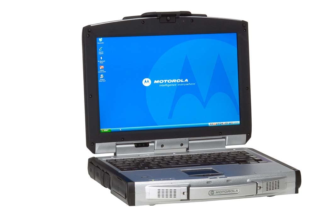
Click to zoom
Application Details
- Equipment Class
- DTS - Digital Transmission System
- Date of Grant
- Oct 02, 2007
- Application Purpose
- Original Equipment
- Date of Application
- Oct 02, 2007
- Equipment Note
- Mobile Computer with WLANabg Module
- Frequency Range
- 5745.00000000 - 5825.00000000
- Company
- Motorola Solutions, Inc.
- Country
- United States
Documents & Files
Document Text
Text extracted from the exhibit documents filed with the FCC. Open a document above to read the original.
Users Manual
ML910™Rugged Notebook User Guide Motorola, Inc. All rights reserved Owner’s Manual R00 Part Number: 6871008P3 1 i TRADEMARKS MOTOROLA, the Stylized M Logo, and ML910 TM RUGGED NOTEBOOK are registered in the U.S. Patent and Trademark Office. All other product or service names are the property of their respective owners. NOTE: Information in this user guide is subject to change without notice. COPYRIGHT Copyright © 2007 Motorola Inc. All rights reserved. No part of this user guide may be transmitted, stored in a retrieval system, or translated into any language or computer language, in any form or by any means, without the prior written permission of Motorola Inc. ii LICENSE AGREEMENT MOTOROLA, INC. (“MOTOROLA”) IS WILLING TO LICENSE THE SOFTWARE EMBEDDED IN THE ENCLOSED PRODUCT (THE “SOFTARE”) TO YOU ONLY ON THE CONDITION THAT YOU ACCEPT ALL OF THE TERMS CONTAINED IN THIS LICENSE AGREEMENT (“AGREEMENT”). PLEASE READ THE TERMS CAREFULLY.YOUR USE OF THE PRODUCT WITH THE EMBEDDED SOFTWARE WILL INDICATE YOUR ASSENT TO THEM. IF YOU DO NOT AGREE TO THESE TERMS, THEN MOTOROLA IS UNWILLING TO LICENSE THE SOFTWARE TO YOU, IN WHICH EVENT YOU SHOULD NOT USE THE PRODUCT WITH THE EMBEDDED SOFTWARE AND YOU SHOULD RETURN IT TO THE PLACE FROM WHICH IT WAS ACQUIRED, AND YOUR MONEY WILL BE REFUNDED. Section 1 GRANT OF LICENSE Motorola hereby grants to You a personal, non-exclusive, non-transferable right to use the Software subject to the Conditions Of Use set forth in Section 2 below and the terms and conditions of this Agreement. Section 2 CONDITIONS OF USE 2.1 Use of the Software outside of the conditions set forth herein is strictly prohibited and will be deemed a breach of this Agreement. 2.2 You shall use the Software (i) only for Your internal business purposes; (ii) only as described in the Software or product documentation; and (iii) in strict accordance with this Agreement. 2.3 You shall not transfer, download, copy, distribute, sublicense, modify, adapt, merge with other software, reverse engineer, prepare derivative works of, de–compile or disassemble any Software for any reason. 2.4 You shall not remove, destroy, or alter any proprietary markings or legends placed upon or contained within the Software, related materials or documentation. 2.5 You shall not export, re-export, resell, ship or divert or cause to be exported, re-exported, resold, shipped, or diverted, directly or indirectly, the Software under this Agreement. Section 3 TITLE AND OWNERSHIP Title to all copies of Software will not pass to You at any time and remains vested exclusively in Motorola or the copyright owner. Motorola or the copyright owner owns and retains all of its proprietary rights in any form concerning the Software, including all rights in patents, patent applications, inventions, copyrights, trade secrets, trademarks, trade names, and other intellectual properties. Nothing in this Agreement is intended to restrict the proprietary rights of Motorola or the copyright owner or to grant by implication or estoppel any proprietary rights. All intellectual property developed, originated, or prepared by Motorola or the copyright owner in connection with providing the Software, products, or related services to You remains vested exclusively in Motorola or the copyright owner, and this Agreement does not grant to You any shared development rights of intellectual property. iii Section 4 CONFIDENTIALITY You acknowledge that all Software contains valuable proprietary information and trade secrets and that unauthorized or improper use of Software will result in irreparable harm to Motorola for which monetary damages would be inadequate and for which Motorola will be entitled to immediate injunctive relief. Accordingly, You will limit access to Software to employees and agents who need to use the Software for Your internal business purposes, and You will take appropriate action with those employees and agents to preserve the confidentiality of Software, using the same degree of care to avoid unauthorized or improper disclosure as You use for the protection of Your own proprietary software, but in no event less than reasonable care. Notwithstanding anything to the contrary herein, You shall have no obligation to preserve the confidentiality of any proprietary information that (i) was in the public domain at the time of disclosure; (ii) entered the public domain through no fault of You; (iii) was given to You free of any obligation to keep it confidential; (iv) is independently developed by You; or (v) is disclosed as required by law provided that You notify Motorola prior to such disclosure and provide Motorola with a reasonable opportunity to respond. Section 5 RIGHT TO USE MOTOROLA’S NAME You shall not, during the term of this Agreement or thereafter, use any trademark of Motorola, or any word or symbol likely to be confused with any Motorola trademark, either alone or in any combination with another word or words. Section 6 PAYMENT The rights granted hereunder are contingent upon payment for the product in which the Software is embedded. Section 7 TERM AND TERMINATION Your right to use Software will begin when You begin using the product with the embedded Software, which constitutes acceptance of the terms and conditions herein, and will continue in perpetuity unless terminated as set forth herein. Your right to use Software will terminate immediately without notice upon a breach of this Agreement by You. Otherwise, this Agreement may be terminated by either party upon thirty (30) days prior written notice. Within thirty (30) days after termination of this Agreement, You will certify to Motorola in writing that through Your best efforts, and to the best of Your knowledge, the original and all copies, in whole in part, in any form, of the Software and all related material and documentation, have been destroyed. Section 8 MAINTENANCE Motorola shall not be responsible for maintenance or field service of the Software under this Agr…
Text truncated - open the document above for the full version.
Users Manual
5-2 BIOS Setup Utility & MLUA When and How to Use the BIOS Setup Utility When to Use You need to run the BIOS Setup Utility when: z You see an error message on the screen requesting you to run Setup. z You want to restore the factory default settings. z You want to modify some specific settings according to the hardware. z You want to modify some specific settings to optimize system performance. Starting BIOS Setup NOTE: 1. The Setup screens shown in this chapter are for your reference only. The actual items or settings on your computer may differ. 2. The Setup utility may have been updated after the publication of this user guide. 3. The settings you select in your operating system might override similar settings in the Setup. To run BIOS Setup, press F2 when the prompt appears in the lower left corner of the screen during system startup. The prompt shows up on the screen for only a few seconds. You must press F2 quickly. The BIOS Setup menu appears as shown next. Moving Around and Making Selections A brief description of keyboard usage is listed next: BIOS Setup Utility & MLUA 5-3 Key Function F1 General Help F2 General Help F9 Load optimal defaults F10 Save and Exit ← → Select Screen ↑ ↓ Select Item ┼ ─ Change Field/Option Enter 1) Brings up the sub-menu when available. 2) Opens or closes the options window when an item is selected. Tab Jumps from one item to another. Esc 1) Exits the BIOS Setup Utility. 2) Returns to the previous menu if in a sub-menu. 3) Closes the options window if one is open. Main Menu 5-4 BIOS Setup Utility & MLUA Advanced Menu CPU Configuration Setup function of “Intel SpeedStep Technology“: Under the slide of “Advanced”, use ÏÐ key to move cursor on the string of “Intel SpeedStep Technology” and you will find the option of “Maximum”, “Minimum”, “Automatic” & “Disabled” on the right top corner of screen. z Maximum: CPU speed is set to maximum. z Minimum: CPU speed is set to minimum. z Automatic: CPU speed is controlled by OS. z Disabled: Use default CPU speed. BIOS Setup Utility & MLUA 5-5 Drive Configuration While entering setup, BIOS auto detects the presence of devices. This displays the status of auto detection of devices. Information of Device 5-6 BIOS Setup Utility & MLUA Peripherals Configuration Enables or disables the feature of “Peripherals Configuration”: Under the slide of “Advanced”, use ÏÐ key to move cursor on the string of peripherals and enable or disable peripherals configuration as you need. System Recovery System Recovery Hotkey: Enable or Disable System Recovery Hotkey by (Ctrl+F9). System Recovery Password: The BIOS support the recovery of the HDD with a Ctrl+ F9 during POST by using one to six character password. BIOS Setup Utility & MLUA 5-7 Set and Change Password: Select Change Password from the System recovery password Setup menu and press <Enter>. Enter New Password: Appears. Type the password and press <Enter>. The screen does not display the characters entered. Retype the password as prompted and press <Enter>. If the password confirmation is incorrect, an error message appears. The password is stored in NVRAM after completes. USB Configuration 5-8 BIOS Setup Utility & MLUA Boot Settings Boot Settings: Under the slide of “Boot”, use ÏÐ key to move cursor on the string of “Boot Settings Configuration”, “Boot Device Priority”, “Hard Disk Drives” & “Removable Drives” for following features. z Boot Setting Configuration: Configure POST behavior. z Boot Device Drives: Set the Boot Device Priority Sequence. z Hard Disk Drives/Removable Drives/CD & DVD Drives: Set the Boot Device Priority Sequence from available Drives. z Network Boot: Enables or Disables Network Boot. z Boot Display Device: Set Display Device used when system boots. z Resume On RTC Alarm: Enable or Disable System wake up on RTC Alarm. BIOS Setup Utility & MLUA 5-9 Boot Settings Configuration Under the Slide of “Boot” use ÏÐ key to move cursor on the string of “Quick Boot”, “Quiet Boot” & “NumLock on Boot” for the features enable or disable. z Quick Boot: Enable or Disable Quick Boot. Enable this option will allows BIOS to skip certain tests while booting, this will decrease the time needed to boot the system. z Quiet Boot: Enable this option will shows logo screen instead of POST messages. z NumLock on Boot: set status & NumLock when system boot. Boot Device Priority Set the boot sequence from the available devices. A device enclosed in parenthesis is has been disabled in the corresponding type menu. 5-10 BIOS Setup Utility & MLUA Security Settings BIOS Password Setup Provide both a Supervisor and a User password. If you use both passwords, the Supervisor password must be set first. The system can be configured so that all users must enter a password every time the system boots or when Setup is executed, using either or either the Supervisor password or User password. The Supervisor and User passwords activate two different levels of password security. If you select password support, you are prompted for a one to six character password. Type the password on the keyboard. The password does not appear on the screen when typed. Make sure you write it down. If you forget it, you must drain NVRAM and reconfigure. Select Security Setup from the Setup main BIOS setup menu. All Security Setup options, such as password protection and virus protection, are described in this section. To access the sub menu for the following items, select the item and press <Enter>: z Change Supervisor Password z Change User Password z Clear User Password z Supervisor Password Indicate whether a supervisor password has been set. If the password has been installed, Installed displays. If not, Not Installed displays. User Password Indicate whether a user password has been set. If the password has been installed, Installed displays. If not, Not Installed displays. Change Supervisor Password: Select Change Supervisor Password from the Security Setup menu and press <Enter>. BIOS Setup Utility & MLUA 5-11…
Text truncated - open the document above for the full version.
External Photos
MOTOROLA FCC ID: ABZ89FT7627 EUT Photographs © 2007 PCTEST Lab. Mobile PC with WLANabg Module Model: ML910 MOTOROLA FCC ID: ABZ89FT7627 EUT Photographs © 2007 PCTEST Lab. Mobile PC with WLANabg Module Model: ML910 MOTOROLA FCC ID: ABZ89FT7627 EUT Photographs © 2007 PCTEST Lab. Mobile PC with WLANabg Module Model: ML910 MOTOROLA FCC ID: ABZ89FT7627 EUT Photographs © 2007 PCTEST Lab. Mobile PC with WLANabg Module Model: ML910 MOTOROLA FCC ID: ABZ89FT7627 EUT Photographs © 2007 PCTEST Lab. Mobile PC with WLANabg Module Model: ML910 MOTOROLA FCC ID: ABZ89FT7627 EUT Photographs © 2007 PCTEST Lab. Mobile PC with WLANabg Module Model: ML910
External Photos
ML910 Antenna Location (Integrated Radio Modems) WLAN Antenna 2 (Secondary RX only) WLAN Antenna 1 (Primary TX and RX) WWAN Antenna 2 (Secondary – RX only -- MC5725) WWAN Antenna 1 (Primary – TX and RX -- MC8775 and MC5725) GPS Antenna Bluetooth Antenna External PCMCIA WMC6300 & WMC7300 Antenna Mount Location
Internal Photos
MOTOROLA FCC ID: ABZ89FT7627 EUT Photographs © 2007 PCTEST Lab. Mobile PC with WLANabg Module Model: ML910 MOTOROLA FCC ID: ABZ89FT7627 EUT Photographs © 2007 PCTEST Lab. Mobile PC with WLANabg Module Model: ML910 MOTOROLA FCC ID: ABZ89FT7627 EUT Photographs © 2007 PCTEST Lab. Mobile PC with WLANabg Module Model: ML910 MOTOROLA FCC ID: ABZ89FT7627 EUT Photographs © 2007 PCTEST Lab. Mobile PC with WLANabg Module Model: ML910
RF Exposure Info
Reviewed by: FCC ID: ABZ89FT7627 MAXIMUM PERMISSIBLE EXPOSURE (MPE) DATA REPORT Quality Manager Test Report S/N: Test Dates: EUT Type: 0708020843.ABZ September 18, 2007 Ruggedized Notebook Page H1 © 2007 PCTEST Engineering Laboratory, Inc. Ver. 2.5 RF Exposure Evaluation – Maximum Permissible Exposure (MPE) Introduction This document attempts to prove the safety of radiation generated by RF devices to the human body. The limit for Maximum Permissible Exposure (MPE), specified in FCC 1.1210, is listed below. The power generated by this product is measured by a power meter. Through use of the Friis transmission formula and the maximum gain of the antenna, the distance from the product at which compliance with the MPE limit is achieved may be calculated. Alternatively, near field measurements may be performed to demonstrate compliance at a specific measurement distance. Near field probe: Wandel & Goltermann EMR-300. Calibration Due: 10/6/2007 This MPE report contains measurements that are applicable to the ML910 when configured with the WLANabg Module and Bluetooth Module . Multiple configurations of the ML910 were measured and are reported herein to ensure that the worst case MPE is reported. EUT: Model: ML910 S/N: 343AA77S0002 Grantee: Motorola FCC ID: ABZ89FT7627 Configuration Table: Motorola FCC IDModules ABZ89FT7627WLAN (3945abg) ABZ89FT7628Bluetooth Reviewed by: FCC ID: ABZ89FT7627 MAXIMUM PERMISSIBLE EXPOSURE (MPE) DATA REPORT Quality Manager Test Report S/N: Test Dates: EUT Type: 0708020843.ABZ September 18, 2007 Ruggedized Notebook Page H2 © 2007 PCTEST Engineering Laboratory, Inc. Ver. 2.5 RF Exposure Limit According to FCC 1.1310: the criteria listed in the following table shall be used to evaluate the environmental impact of human exposure to radio-frequency (RF) radiation as specified in 1.1307(b). Frequency Range (MHz) Electric Field Strength (V/m) Magnetic Field Strength (A/m) Power Density (mW/cm 2 ) Average Time (Minutes) (A) Limits For Occupational / Control Exposures (f = frequency) 30-300 61.4 0.163 1.0 6 300-1500 ... ... f/300 6 1500-100,000 ... ... 5.0 6 (B) Limits For General Population / Uncontrolled Exposure (f = frequency) 30-300 27.5 0.073 0.2 30 300-1500 ... ... f/1500 30 1500-100,000 ... ... 1.0 30 Table H-1. Limits For Maximum Permissible Exposure (MPE) Friis Transmission Formula Friis transmission formula: P d = (P out *G) / (4πr 2 ) Where, P d = Power Density (mW/cm 2 ) P out = output power to antenna (mW) G = gain of antenna in linear scale π = 3.1416 r = distance between observation point and center of the radiator (cm) EUT Operating Condition Software provided by the client enabled the EUT to transmit and receive data at lowest, middle, and highest channels individually. Measurement Procedure: Measurements of the RF fields are measured in accordance with OET Bulletin 65. A broad-band radiation probe is used in making the measurements. For devices that contain multiple transmitters that operate simultaneously all transmitters are activated and transmitting during the test. For all measurements the EUT is placed on a non-metallic 80cm high table in a shielded anechoic chamber and the field probe is placed 20cm from the plane of the EUT. The probe is moved across the entire surface of the plane (i.e. front, right side, rear, left side) and the highest reading for each plane is recorded. The RF levels are then compared to the MPE limit to determine compliance. Climate Condition The temperature and relative humidity: 22 ̊C and 78% RH Reviewed by: FCC ID: ABZ89FT7627 MAXIMUM PERMISSIBLE EXPOSURE (MPE) DATA REPORT Quality Manager Test Report S/N: Test Dates: EUT Type: 0708020843.ABZ September 18, 2007 Ruggedized Notebook Page H3 © 2007 PCTEST Engineering Laboratory, Inc. Ver. 2.5 Measurement Results Frequency (MHz) Conducted Level (dBm) Measurement Distance (cm) Front MPE reading mW/cm 2 Rear MPE reading mW/cm 2 Right MPE reading mW/cm 2 Left MPE reading mW/cm 2 Limit mW/cm 2 2441 (BT) 3.97 2412 (802.11b) 15.86 20 0.0032 0.0032 0.0013 0.0053 See Table Table H-2. MPE Measurement Result (Multiple Transmitters – Mid Channel) Frequency (MHz) Conducted Level (dBm) Measurement Distance (cm) Front MPE reading mW/cm 2 Rear MPE reading mW/cm 2 Right MPE reading mW/cm 2 Left MPE reading mW/cm 2 Limit mW/cm 2 2441 (BT) 3.97 2437 (802.11g) 14.91 20 0.0036 0.025 0.0012 0.0032 See Table Table H-3. MPE Measurement Result (Multiple Transmitters - Mid Channel) Frequency (MHz) Conducted Level (dBm) Measurement Distance (cm) Front MPE reading mW/cm 2 Rear MPE reading mW/cm 2 Right MPE reading mW/cm 2 Left MPE reading mW/cm 2 Limit mW/cm 2 2441 (BT) 3.97 5745 (802.11a) 14.42 20 0.0035 0.0028 0.0012 0.0044 See Table Table H-4. MPE Measurement Result (Multiple Transmitters - Mid Channel) Note: Measurements are made while all transmitters are operating simultaneously. Frequency (MHz) Conducted Level (dBm) Measurement Distance (cm) Front MPE reading mW/cm 2 Rear MPE reading mW/cm 2 Right MPE reading mW/cm 2 Left MPE reading mW/cm 2 Limit mW/cm 2 2441 (BT) 3.97 5180 (UNII) 14.52 20 0.0029 0.0035 0.0027 0.0036 See Table Table H-5. MPE Measurement Result (Multiple Transmitters - Mid Channel) Conclusion The device meets the mobile 20cm separation distance as specified in Section 2.1091 of the FCC Rules. An appropriate RF exposure compliance statement will be placed in the user’s manual.
RF Exposure Info
Reviewed by: FCC ID: QJEWMC6300704 MAXIMUM PERMISSIBLE EXPOSURE (MPE) DATA REPORT Quality Manager Test Report S/N: Test Dates: EUT Type: 0709251111.QJE September 18, 2007 Ruggedized Notebook Page H1 © 2007 PCTEST Engineering Laboratory, Inc. Ver. 2.5 RF Exposure Evaluation – Maximum Permissible Exposure (MPE) Introduction This document attempts to prove the safety of radiation generated by RF devices to the human body. The limit for Maximum Permissible Exposure (MPE), specified in FCC 1.1210, is listed below. The power generated by this product is measured by a power meter. Through use of the Friis transmission formula and the maximum gain of the antenna, the distance from the product at which compliance with the MPE limit is achieved may be calculated. Alternatively, near field measurements may be performed to demonstrate compliance at a specific measurement distance. Near field probe: Wandel & Goltermann EMR-300. Calibration Due: 10/6/2007 This MPE report contains measurements that are applicable to the ML910 when configured with the WMC6300 PCMCIA Wireless Modem Card. Multiple configurations of the ML910 were measured and are reported herein to ensure that the worst case MPE is reported. EUT: Model: ML910 S/N: 343AA77S0002 Grantee: Motorola FCC ID: QJEWMC6300704 Configuration Table: Motorola FCC IDModules ABZ89FT7627WLAN (3945abg) ABZ89FT7628Bluetooth QJEWMC6300704WMC6300 Reviewed by: FCC ID: QJEWMC6300704 MAXIMUM PERMISSIBLE EXPOSURE (MPE) DATA REPORT Quality Manager Test Report S/N: Test Dates: EUT Type: 0709251111.QJE September 18, 2007 Ruggedized Notebook Page H2 © 2007 PCTEST Engineering Laboratory, Inc. Ver. 2.5 RF Exposure Limit According to FCC 1.1310: the criteria listed in the following table shall be used to evaluate the environmental impact of human exposure to radio-frequency (RF) radiation as specified in 1.1307(b). Frequency Range (MHz) Electric Field Strength (V/m) Magnetic Field Strength (A/m) Power Density (mW/cm 2 ) Average Time (Minutes) (A) Limits For Occupational / Control Exposures (f = frequency) 30-300 61.4 0.163 1.0 6 300-1500 ... ... f/300 6 1500-100,000 ... ... 5.0 6 (B) Limits For General Population / Uncontrolled Exposure (f = frequency) 30-300 27.5 0.073 0.2 30 300-1500 ... ... f/1500 30 1500-100,000 ... ... 1.0 30 Table H-1. Limits For Maximum Permissible Exposure (MPE) Friis Transmission Formula Friis transmission formula: P d = (P out *G) / (4πr 2 ) Where, P d = Power Density (mW/cm 2 ) P out = output power to antenna (mW) G = gain of antenna in linear scale π = 3.1416 r = distance between observation point and center of the radiator (cm) EUT Operating Condition Software provided by the client enabled the EUT to transmit and receive data at lowest, middle, and highest channels individually. Measurement Procedure: Measurements of the RF fields are measured in accordance with OET Bulletin 65. A broad-band radiation probe is used in making the measurements. For devices that contain multiple transmitters that operate simultaneously all transmitters are activated and transmitting during the test. For all measurements the EUT is placed on a non-metallic 80cm high table in a shielded anechoic chamber and the field probe is placed 20cm from the plane of the EUT. The probe is moved across the entire surface of the plane (i.e. front, right side, rear, left side) and the highest reading for each plane is recorded. The RF levels are then compared to the MPE limit to determine compliance. Climate Condition The temperature and relative humidity: 22 ̊C and 78% RH Reviewed by: FCC ID: QJEWMC6300704 MAXIMUM PERMISSIBLE EXPOSURE (MPE) DATA REPORT Quality Manager Test Report S/N: Test Dates: EUT Type: 0709251111.QJE September 18, 2007 Ruggedized Notebook Page H3 © 2007 PCTEST Engineering Laboratory, Inc. Ver. 2.5 Measurement Results Frequency (MHz) Conducted Level (dBm) Measurement Distance (cm) Front MPE reading mW/cm 2 Rear MPE reading mW/cm 2 Right MPE reading mW/cm 2 Left MPE reading mW/cm 2 Limit mW/cm 2 2441 (BT) 3.97 2412 (802.11b) 15.86 2450 (MESH) 24.50 20 0.0366 0.0440 0.0261 0.0272 See Table Table H-2. MPE Measurement Result (Multiple Transmitters) Frequency (MHz) Conducted Level (dBm) Measurement Distance (cm) Front MPE reading mW/cm 2 Rear MPE reading mW/cm 2 Right MPE reading mW/cm 2 Left MPE reading mW/cm 2 Limit mW/cm 2 2441 (BT) 3.97 2437 (802.11g) 14.91 2450 (MESH) 24.50 20 0.0596 0.0461 0.0273 0.0245 See Table Table H-3. MPE Measurement Result (Multiple Transmitters) Frequency (MHz) Conducted Level (dBm) Measurement Distance (cm) Front MPE reading mW/cm 2 Rear MPE reading mW/cm 2 Right MPE reading mW/cm 2 Left MPE reading mW/cm 2 Limit mW/cm 2 2441 (BT) 3.97 5745 (802.11a) 14.42 2450 (MESH) 24.50 20 0.0482 0.0391 0.0200 0.0220 See Table Table H-4. MPE Measurement Result (Multiple Transmitters) Frequency (MHz) Conducted Level (dBm) Measurement Distance (cm) Front MPE reading mW/cm 2 Rear MPE reading mW/cm 2 Right MPE reading mW/cm 2 Left MPE reading mW/cm 2 Limit mW/cm 2 2441 (BT) 3.97 5180 (UNII) 14.52 2450 (MESH) 24.50 20 0.0561 0.0470 0.0239 0.0303 See Table Table H-5. MPE Measurement Result (Multiple Transmitters) Note: Measurements are made while all transmitters are operating simultaneously. Reviewed by: FCC ID: QJEWMC6300704 MAXIMUM PERMISSIBLE EXPOSURE (MPE) DATA REPORT Quality Manager Test Report S/N: Test Dates: EUT Type: 0709251111.QJE September 18, 2007 Ruggedized Notebook Page H4 © 2007 PCTEST Engineering Laboratory, Inc. Ver. 2.5 Conclusion The device meets the mobile 20cm separation distance as specified in Section 2.1091 of the FCC Rules. An appropriate RF exposure compliance statement will be placed in the user’s manual.
RF Exposure Info
Reviewed by: FCC ID: QJEWMC73000705 MAXIMUM PERMISSIBLE EXPOSURE (MPE) DATA REPORT Quality Manager Test Report S/N: Test Dates: EUT Type: 0709251112.QJE September 18, 2007 Ruggedized Notebook Page H1 © 2007 PCTEST Engineering Laboratory, Inc. Ver. 2.5 RF Exposure Evaluation – Maximum Permissible Exposure (MPE) Introduction This document attempts to prove the safety of radiation generated by RF devices to the human body. The limit for Maximum Permissible Exposure (MPE), specified in FCC 1.1210, is listed below. The power generated by this product is measured by a power meter. Through use of the Friis transmission formula and the maximum gain of the antenna, the distance from the product at which compliance with the MPE limit is achieved may be calculated. Alternatively, near field measurements may be performed to demonstrate compliance at a specific measurement distance. Near field probe: Wandel & Goltermann EMR-300. Calibration Due: 10/6/2007 This MPE report contains measurements that are applicable to the ML910 when configured with the WMC7300 PCMCIA Wireless Modem Card. Multiple configurations of the ML910 were measured and are reported herein to ensure that the worst case MPE is reported. EUT: Model: ML910 S/N: 343AA77S0002 Grantee: Motorola FCC ID: QJEWMC73000705 Configuration Table: Motorola FCC IDModules ABZ89FT7627WLAN (3945abg) ABZ89FT7628Bluetooth QJEWMC73000705WMC7300 Reviewed by: FCC ID: QJEWMC73000705 MAXIMUM PERMISSIBLE EXPOSURE (MPE) DATA REPORT Quality Manager Test Report S/N: Test Dates: EUT Type: 0709251112.QJE September 18, 2007 Ruggedized Notebook Page H2 © 2007 PCTEST Engineering Laboratory, Inc. Ver. 2.5 RF Exposure Limit According to FCC 1.1310: the criteria listed in the following table shall be used to evaluate the environmental impact of human exposure to radio-frequency (RF) radiation as specified in 1.1307(b). Frequency Range (MHz) Electric Field Strength (V/m) Magnetic Field Strength (A/m) Power Density (mW/cm 2 ) Average Time (Minutes) (A) Limits For Occupational / Control Exposures (f = frequency) 30-300 61.4 0.163 1.0 6 300-1500 ... ... f/300 6 1500-100,000 ... ... 5.0 6 (B) Limits For General Population / Uncontrolled Exposure (f = frequency) 30-300 27.5 0.073 0.2 30 300-1500 ... ... f/1500 30 1500-100,000 ... ... 1.0 30 Table H-1. Limits For Maximum Permissible Exposure (MPE) Friis Transmission Formula Friis transmission formula: P d = (P out *G) / (4πr 2 ) Where, P d = Power Density (mW/cm 2 ) P out = output power to antenna (mW) G = gain of antenna in linear scale π = 3.1416 r = distance between observation point and center of the radiator (cm) EUT Operating Condition Software provided by the client enabled the EUT to transmit and receive data at lowest, middle, and highest channels individually. Measurement Procedure: Measurements of the RF fields are measured in accordance with OET Bulletin 65. A broad-band radiation probe is used in making the measurements. For devices that contain multiple transmitters that operate simultaneously all transmitters are activated and transmitting during the test. For all measurements the EUT is placed on a non-metallic 80cm high table in a shielded anechoic chamber and the field probe is placed 20cm from the plane of the EUT. The probe is moved across the entire surface of the plane (i.e. front, right side, rear, left side) and the highest reading for each plane is recorded. The RF levels are then compared to the MPE limit to determine compliance. Climate Condition The temperature and relative humidity: 22 ̊C and 78% RH Reviewed by: FCC ID: QJEWMC73000705 MAXIMUM PERMISSIBLE EXPOSURE (MPE) DATA REPORT Quality Manager Test Report S/N: Test Dates: EUT Type: 0709251112.QJE September 18, 2007 Ruggedized Notebook Page H3 © 2007 PCTEST Engineering Laboratory, Inc. Ver. 2.5 Measurement Results Frequency (MHz) Conducted Level (dBm) Measurement Distance (cm) Front MPE reading mW/cm 2 Rear MPE reading mW/cm 2 Right MPE reading mW/cm 2 Left MPE reading mW/cm 2 Limit mW/cm 2 2441 (BT) 3.97 2412 (802.11b) 15.86 4965 (MESH) 26.06 20 0.0492 0.0289 0.0049 0.0232 See Table Table H-2. MPE Measurement Result (Multiple Transmitters) Frequency (MHz) Conducted Level (dBm) Measurement Distance (cm) Front MPE reading mW/cm 2 Rear MPE reading mW/cm 2 Right MPE reading mW/cm 2 Left MPE reading mW/cm 2 Limit mW/cm 2 2441 (BT) 3.97 2437 (802.11g) 14.91 4965 (MESH) 26.06 20 0.0448 0.0281 0.0054 0.0226 See Table Table H-3. MPE Measurement Result (Multiple Transmitters) Frequency (MHz) Conducted Level (dBm) Measurement Distance (cm) Front MPE reading mW/cm 2 Rear MPE reading mW/cm 2 Right MPE reading mW/cm 2 Left MPE reading mW/cm 2 Limit mW/cm 2 2441 (BT) 3.97 5745 (802.11a) 14.42 4965 (MESH) 26.06 20 0.0540 0.0338 0.0059 0.0254 See Table Table H-4. MPE Measurement Result (Multiple Transmitters) Frequency (MHz) Conducted Level (dBm) Measurement Distance (cm) Front MPE reading mW/cm 2 Rear MPE reading mW/cm 2 Right MPE reading mW/cm 2 Left MPE reading mW/cm 2 Limit mW/cm 2 2441 (BT) 3.97 5180 (UNII) 14.52 4965 (MESH) 26.06 20 0.0572 0.0242 0.0056 0.0276 See Table Table H-5. MPE Measurement Result (Multiple Transmitters) Note: Measurements are made while all transmitters are operating simultaneously. Reviewed by: FCC ID: QJEWMC73000705 MAXIMUM PERMISSIBLE EXPOSURE (MPE) DATA REPORT Quality Manager Test Report S/N: Test Dates: EUT Type: 0709251112.QJE September 18, 2007 Ruggedized Notebook Page H4 © 2007 PCTEST Engineering Laboratory, Inc. Ver. 2.5 Conclusion The device meets the mobile 20cm separation distance as spec…
Text truncated - open the document above for the full version.
Contact Information
Applicant
Matthew Nawrocki
Technical Contact
PCTEST Engineering Laboratory, Inc.Randy Ortanez
[email protected]410-290-6652
6660-B Dobbin Road · Columbia, Maryland · United States
Test Firm
PCTEST Engineering Laboratory, Inc.Randy Ortanez
Technical Specifications
| # | Rule Parts | Frequency Range | Power Output |
|---|---|---|---|
| 2 | 15C | 5.75 GHz - 5.83 GHz | 27.70 mW |
Other Applications from Motorola Solutions, Inc.

ABZ89FT4940
Aug 06, 2026Non Broadcast Transmitter
Equipment Class
TNB - Licensed Non-Broadcast Station TransmitterABZ89FT4950
Jun 25, 2026Non-Broadcast Transmitter
Equipment Class
TNB - Licensed Non-Broadcast Station TransmitterABZ89FT5901
Jun 20, 2024Non Broadcast Transmitter
Equipment Class
TNB - Licensed Non-Broadcast Station Transmitter
ABZ99FT5101B
May 02, 2023Non Broadcast Transmitter
Equipment Class
PCB - PCS Licensed Transmitter
ABZ99FT3095B
Mar 26, 2023Non Broadcast Transmitter
Equipment Class
TNB - Licensed Non-Broadcast Station Transmitter