ABZ99FT3003GTX 800MHZ Mobile Radio
Motorola Solutions, Inc.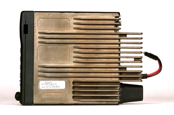
Click to zoom
Application Details
- Equipment Class
- TNB - Licensed Non-Broadcast Station Transmitter
- Date of Grant
- Jun 18, 2000
- Application Purpose
- Original Equipment
- Date of Application
- Dec 08, 1999
- Equipment Note
- GTX 800MHZ Mobile Radio
- Frequency Range
- 851.00000000 - 866.00000000
- Company
- Motorola Solutions, Inc.
- Country
- United States
Documents & Files
Document Text
Text extracted from the exhibit documents filed with the FCC. Open a document above to read the original.
Users Manual
USER’SGUIDE GTX ™ LTR ® TRUNKED MOBILE RADIO , Motorola, GTX, Digital Private-Line are trademarks of Motorola. © 1999 by Motorola, Inc., Radio Products Group 1000 W. Washington St. Printed 1999. All Rights Reserved. 1 English CONTENTS Introduction General Information............................................................................................................... 3 Warnings, Cautions, and Notes............................................................................................. 3 Multiple Selection .................................................................................................................. 4 Talkgroup Selection ............................................................................................................... 4 Features and Advantages of Trunking................................................................................... 4 Getting Started Controls, Buttons, Indicators, and Connectors ...................................................................... 5 Display Icons ......................................................................................................................... 6 Display Character Summary ................................................................................................. 7 Alert Tone Indicators ............................................................................................................. 8 Basic Radio Operation Turning the Radio On / Off .................................................................................................... 9 Trunked Modes...................................................................................................................... 9 Selecting a Trunked Mode ............................................................................................... 9 Receiving a Call (Trunked Mode)................................................................................... 10 Transmitting on a Trunked Mode .................................................................................... 10 Conventional Channels ....................................................................................................... 11 Selecting a Conventional Channel ................................................................................. 11 Receiving a Call (Conventional Channels)..................................................................... 11 Transmitting on a Conventional Channel ....................................................................... 12 Monitoring ......................................................................................................................13 Trunked Telephone Operation Introduction.......................................................................................................................... 14 Making a Telephone Call ..................................................................................................... 14 Answering a Telephone Call ................................................................................................ 15 Scan Operation Introduction.......................................................................................................................... 16 Turning Scan On/Off............................................................................................................16 Types of Scan...................................................................................................................... 16 All Group Scan............................................................................................................... 16 System Scan.................................................................................................................. 16 User Scan ......................................................................................................................17 Programming/Viewing a Scan List ...................................................................................... 17 Nuisance Delete .................................................................................................................. 18 Talkback Delay .................................................................................................................... 18 Off-Hook Suspend Scan...................................................................................................... 18 Additional Features Horn/Lights .......................................................................................................................... 19 Data Compatability ..............................................................................................................19 GTX LTR Mobile Radio User Guide 2 English Accessories................................................................................................................................................ 20 Important General Safety Information Restrictions ......................................................................................................................... 21 Operational Warnings.......................................................................................................... 21 Exposure to Radio Frequency Energy ................................................................................ 22 Electromagnetic Interference/Compatibility ......................................................................... 23 General Safety Information ................................................................................................. 24 Troubleshooting ................................................................................................................... 25 Parts Information ................................................................................................................. 26 Computer Software Copyrights ........................................................................................... 26 GTX LTR Mobile…
Text truncated - open the document above for the full version.
Attestation Statements
MOTOROLA INCFCC ID: ABZ99FT3003 EXHIBIT 3 ATTESTATION STATEMENTS The technical data supplied with this application, having been taken under my supervision is hereby duly certified. The following is a statement of my qualifications: 1) BSEEIllinois Institute of Technology, Chicago, IL MSEE Illinois Institute of Technology, Chicago 2) 32 years experience in the development, testing and certification of Land Mobile Communications Products NAME: Robert O. Loving, Jr. SIGNATURE: DATE: November 9, 1999 POSITION:Principal Staff Engineer I hereby certify that the above application was prepared under my direction and that to the best of my knowledge and belief, the facts set forth in the application and accompanying technical data are true and correct: NAME: Jean-Robert Achille SIGNATURE: DATE: November 9, 1999 POSITION: Engineering Section Manager
Block Diagram
MOTOROLA INC.FCC ID: ABZ99FT3003 EXHIBIT 5 CIRCUIT DESCRIPTION A general description of the overall circuit is covered in the instruction manual. This section provides the description of circuits required by subpart 2.983 of the Commissions’ rules. Circuits not described in the manual are covered in this exhibit. This exhibit contains descriptions of the frequency generation, modulation and transmitter circuits in accordance with FCC Rules Part 2.983(d). The following descriptions are included: EXHIBIT 5A - Means for Frequency Stabilization, 2.983 (d) 10 EXHIBIT 5B - Means for Limiting Modulation and Attenuation of Higher Audio Frequencies, 2.983 (d) 11 EXHIBIT 5C - Means for Attenuation of Spurious Emissions, 2.983 (d) 11 EXHIBIT 5D - Means for Limiting Power Output, 2.983 (d) 11 EXHIBIT 5E - Modulation Techniques, 2.983 (d) 12 MOTOROLA INC.FCC ID: ABZ99FT3003 EXHIBIT 5A MEANS FOR FREQUENCY STABILIZATION Circuit Description: A 16.8 MHz Temperature Controlled Crystal Oscillator (TCXO), U5700 (a “Pendulum” oscillator), maintains frequency stability of the transmitted carrier. The TCXO features low current drain and a ±1.5- ppm frequency versus temperature capability. In addition, this TCXO offers digital tuning and a temperature referenced 5 bit Digital to Analog Converter (DAC). Frequency tuning has 128 steps of resolution. The 16.8 MHz output frequency of the TCXO is divided into one of three reference frequencies in the fractional-N frequency synthesizer IC, U5702. These reference frequencies are compared to the divided outputs of the VCOs in a phase detector. The output of the phase detector provides a DC correction voltage back to the VCOs. The carrier frequency for conventional operation, in the range of 806 to 821 MHz, is generated using a Bipolar Transistor, Q5706, configured as a voltage controlled oscillator (VCO). The Q5706 VCO also supplies the injection power for the first mixer of the receiver. The carrier frequency for talk-around operation, in the range of 851 to 866 MHz, is generated using a Bipolar Transistor, Q5704, configured as a voltage controlled oscillator (VCO). Only one VCO is operating during transmissions. The output of one or the other of the VCOs is applied to the input of fractional-N, frequency synthesizer integrated circuit, U5702. U5702 consists of a phase-locked loop circuit with the output of the VCOs fed to a programmable divider chain. The divide ratios are determined from information stored in the Electrically Erasable Programmable Read Only Memory (EEPROM) in the microcomputer, U0101, and bussed to the synthesizer. The microcomputer extracts the data for the division ratios as determined by the mode (channel) of operation selected. Using a time averaged algorithm a combination of divide ratios is used so that the reference frequency can be a much higher value than the value of the frequency resolution. Modulation occurs by a combination of directly coupling the modulation signal to the low pass filter in the loop and by processing the modulation signal to alter the divider values. A block diagram of the VCO/Synthesizer system is shown in Figure 5.1. Figure 5.1 – Carrier Frequency Generation and Stabilization MOTOROLA INC.FCC ID: ABZ99FT3003 EXHIBIT 5B MEANS FOR LIMITING MODULATION AND ATTENUATION OF HIGHER AUDIO FREQUENCIES Circuit Description: Modulation limiting is accomplished within the custom audio processor IC, U0201 (“ASFIC”). The limiting action itself occurs at the rails (i.e., 5V and ground). Using an operational amplifier with feedback, very hard limiting is obtained. The limited modulation signal output of the limiter is applied to a low-pass filter in U0201. The filter is a fifth-order, Butterworth switched capacitor filter with the 3-dB roll-off corner frequency located at 3250 Hz. The output of the low-pass filter is applied to the input of the electronic attenuator. The electronic attenuator is controlled by the microcomputer of the transceiver. To keep the deviation constant over the RF frequency range, the microcomputer adds the proper correction factor to the attenuator. A block diagram of the limiting and low pass filtering is shown in figure 5.2. Figure 5.2 – Transmitter Modulation Limiting and Lowpass Filtering MOTOROLA INC.FCC ID: ABZ99FT3003 EXHIBIT 5C MEANS FOR ATTENUATION OF SPURIOUS EMISSIONS Circuit Description: The final stage of the RF power amplifier circuit feeds a low-pass filter in order to attenuate harmonics of the output frequency as well as spurious outputs. The filter is a seventh-order, 0.1 dB Chebychev design using LC reactive elements. Shielding of the transmitter RF power amplifier circuit also attenuates spurious emissions. The circuit diagram may be found in Figure 5.3. U U U U U U U U U U U U U U U U U U U U U U U U U U U U U U U U C1 3.0 pF C9 3.0 pF Figure 5.3 – Transmitter Lowpass Filter MOTOROLA INC.FCC ID: ABZ99FT3003 EXHIBIT 5D MEANS FOR LIMITING POWER OUTPUT Circuit Description A forward power detecting, current sensing ALC loop regulates the output power of the transmitter. The forward power detector is placed after the harmonic filter and before the antenna connector. The forward power detector is a microstrip printed circuit, directional coupler. A sample of the forward energy is rectified by CR6506 to produce a dc voltage proportional to the output power of the transmitter. That voltage is applied to the Power Control IC, U1503, and is compared to a preprogrammed voltage reference. Any difference between the two inputs generates an error voltage. The error voltage is amplified and the resulting output from the power control is used as a bias control voltage for the first transmitter stage, Q6501. The bias control voltage changes the gain of Q6501 to maintain constant dc voltage from the power detector and, therefore, transmitter output power. The voltage drop across current sensing resistor R6520 is proportional to the collector current of the final power amplifier transistor, Q6505. The volta…
Text truncated - open the document above for the full version.
Cover Letter(s)
MOTOROLA, Inc FCC ID:ABZ99FT3003 EXHIBIT 1 Date: December 09,1999 Authorization & Evaluation Division. Federal Communications Commission Laboratory. 7435 Oakland Mills Road. Columbia, MD 21046. Att: George Tannahill, Frank Coperich. Subject: Application for Certification of Transmitter with FCC ID# ABZ99FT3003 Gentlemen: Motorola Inc. 5201 Tollview Dr., Rolling Meadows, IL, submits application for certification of the equipment identified by ABZ99FT3003. This transmitter is primarily intended for use in a commercial two way land mobile radio application with capabilities for clear and encrypted (Analog Inversion Scrambler) communications with transmit power output variable from 20 Watts (+43 dBm) to 40 Watts (+46 dBm). The transmitter complies with section 90.203 of the rules in that the operator cannot directly program transmit frequencies using only the normally accessible external controls of the unit. Enclosed is a complete Certification application Sincerely, Donna Tokarz Tel: (847) 576-7245Fax: (847) 538-4312 MOTOROLA, Inc FCC ID:ABZ99FT3003 EXHIBIT 1 LIST OF EXHIBITS DESCRIPTION EXHIBIT REFERENCE I. Cover Letter12.1033 II. Identification Label Information2 General Information2A 1. Production Plans 2. Application References 3. Data Submittal Procedure III.Attestation Statements3 IV.External Photographs4 V.Circuit Descriptions5 1. Means for Frequency Stabilization5A 2. Means for Limiting Modulation5B 3. Means for Attenuation of Higher Audio Frequencies5C 4. Means for Attenuation of Spurious Emissions5D 5. Means for Limiting Power Output5E 6. Modulation Techniques5F VI. Schematic Diagrams6 VII. Test Report7 1. Data Index7 2. RF Output Data7A 3. Modulation Characteristics A. Audio Response & Low Pass Filter Response7B, 7C B. Modulation Limiting7D 4. Occupied Bandwidth7E 5. Conducted Spurious Emissions 7F 6. Radiated Spurious Emissions7G 7. Frequency Stability vs. Temperature7H 8. Frequency Stability vs. Voltage7J VIII.Test Set-up Procedures8 IX. Instruction Manual9 X. Internal Photographs10 XI.Parts List and Tune-up Procedures11 1. Function of RF Semiconductors & Active Devices 11A 2. List of Recommended Test Equipment for Servicing11B 3. Tune-up Information11C XII.RF Exposure Information12 XIII.Operational Description13 1. Technical Characteristics 2. Application
Cover Letter(s)
Re:FCC ID ABZ99FT3003 Applicant:Motorola, Inc. Correspondence Reference Number: 13461 731 Confirmation Number:EA96210 Date of Original E-mail:2000 April 14 Date of Response:2000 May 19 Mr. Error Chang: In response to your inquiries in your e-mail dated 2000 April 14, Motorola, Inc. submits the following answers and clarifications. Your questions are repeated here, in quotation marks, to provide continuity. “1. The MPE report indicated tests were performed at 20 cm from the side of the vehicle and 60 cm from the back of the vehicle for the antenna configurations evaluated. Normally measurements should be made at the closest distance persons may normally be from the antenna so that the proper distance can be used in the installation procedures without imposing any burden on the radio operator to maintain the additionally needed separation distance as indicated in the manual.” For clarification the test lab procedures prescribe fixed distances to the antenna of 30, 60, or 90 cm depending on the transmitter power output and consistent with the distance instructions in both the User Manual and the Installation Manuals. One additional prescribed procedural item is to not allow the probe to be closer than 20 cm from the vehicle body to prevent erroneous measurements per the guidance provided by ANSI/IEEE C95.1, Section 6.6. Hence t he measurements made for this nominal 35 watt radio were conducted at a distance of 20 cm from the side of the vehicle for a roof center mount antenna and 60 cm from the antenna for a center trunk mount antenna. “Please clarify with respect to the following - (a) MPE report indicated this radio was evaluated for controlled/occupational exposure environment. Please confirm if marketing of this radio will be limited to occupational workers who will be trained and have knowledge to control the exposure conditions for all persons exposed to the antenna of this radio and maintaining the needed distance proposed in the manual (2 feet from the vehicle) to ensure RF exposure compliance. If so, please clarify how such training will be implemented so that additional clarifications will be unnecessary for satisfying uncontrolled MPE limits.” This device is designed specifically for use by occupational workers (occupational/ controlled environment) and will be marketed to federal gover nment and public safety agencies and private businesses such as utilities, airlines and railroads. These radios are typically used in a disciplined way to help improve productivity, control and coordinate work teams, and enhance personal safety. Push-to-talk two-way radio conversations are measured in seconds, not minutes. The user's manual provides clear instructions on proper usage, including a specific section on EME. As a point of clarification the user instructions relative to distance are referenced to the antenna and not to the vehicle. While user training is the responsibility of the customer, who uses manuals, instructional sessions or other means to inform workers, Motorola also offers its customers training classes on the proper use of two-way radios. “(b) If the radio is not intended for use in occupational environment that requires workers to have the needed knowledge to qualify for the higher controlled MPE limits, please clarify and/or provide additional data to indicate exposure at the side of the vehicle, closest to the antenna configurations, can comply with uncontrolled MPE limit. Note: the roof center antenna w hen mounted on the left or right side of the trunk edge, as suggested in the manual, would represent worst case.” As noted above the radio is intended for use in the occupational environment. The Antenna manual contained in Exhibit 12D is a generic manual for a series of 12 different antennas that are selectively specified by a variety of different radio models. The User Manual for this radio specifies only one of the twelve antennas, the HAF4002A; i.e. the Trunk Lip Mount antenna is not specified for this radio. “2. If necessary, the relevant installation and user information should be revised accordingly.” The manual previously uploaded as Exhibit 12D has been modified to add the following note for the Trunk Lip Antenna Models: "Not recommended for transmitters with power output 7 watts or greater" New versions of the Radio, the Mobile ¼-Wavelength Antennas and the Mobile Gain Antennas installation manuals are provided as replacements for Exhibit 12C, Exhibit 12D and Exhibit 12E, respectively. Regards, Robert O. Loving, Jr.
Cover Letter(s)
Re:FCC ID ABZ99FT3003 Applicant:Motorola, Inc. Correspondence Reference Number: 13461 731 Confirmation Number:EA96210 Date of Original E-mail:2000 April 14 Date of Response:2000 May 23 Mr. Errol Chang: In response to your inquiries in your e-mail dated 2000 April 14, Motorola, Inc. submits the following answers and clarifications. Your questions are repeated here, in quotation marks, to provide continuity. “1. The MPE report indicated tests were performed at 20 cm from the side of the vehicle and 60 cm from the back of the vehicle for the antenna configurations evaluated. Normally measurements should be made at the closest distance persons may normally be from the antenna so that the proper distance can be used in the installation procedures without imposing any burden on the radio operator to maintain the additionally needed separation distance as indicated in the manual.” For clarification the test lab procedures prescribe fixed distances to the antenna of 30, 60, or 90 cm depending on the transmitter power output and consistent with the distance instructions in both the User Manual and the Installation Manuals. One additional prescribed procedural item is to not allow the probe to be closer than 20 cm from the vehicle body to prevent erroneous measurements per the guidance provided by ANSI/IEEE C95.1, Section 6.6. Hence t he measurements made for this nominal 35 watt radio were conducted at a distance of 20 cm from the side of the vehicle for a roof center mount antenna and 60 cm from the antenna for a center trunk mount antenna. “Please clarify with respect to the following - (a) MPE report indicated this radio was evaluated for controlled/occupational exposure environment. Please confirm if marketing of this radio will be limited to occupational workers who will be trained and have knowledge to control the exposure conditions for all persons exposed to the antenna of this radio and maintaining the needed distance proposed in the manual (2 feet from the vehicle) to ensure RF exposure compliance. If so, please clarify how such training will be implemented so that additional clarifications will be unnecessary for satisfying uncontrolled MPE limits.” This device is designed specifically for use by occupational workers (occupational/ controlled environment) and will be marketed to federal gover nment and public safety agencies and private businesses such as utilities, airlines and railroads. These radios are typically used in a disciplined way to help improve productivity; control and coordinate work teams; and, enhance personal safety. Push-to-talk two-way radio conversations are measured in seconds, not minutes. The user's manual provides clear instructions on proper usage, including a specific section on EME. As a point of clarification the user instructions relative to distance are referenced to the antenna and not to the vehicle. While user training is the responsibility of the customer, who uses manuals, instructional sessions or other means to inform workers, Motorola also offers its customers training classes on the proper use of two-way radios. “(b) If the radio is not intended for use in occupational environment that requires workers to have the needed knowledge to qualify for the higher controlled MPE limits, please clarify and/or provide additional data to indicate exposure at the side of the vehicle, closest to the antenna configurations, can comply with uncontrolled MPE limit. Note: the roof center antenna w hen mounted on the left or right side of the trunk edge, as suggested in the manual, would represent worst case.” As noted above the radio is intended for use in the occupational environment. The Antenna manual contained in Exhibit 12D is a generic manual for a series of 12 different antennas that are selectively specified by a variety of different radio models. The User Manual for this radio specifies only one of the twelve antennas, the HAF4002A; i.e. the Trunk Lip Mount antenna is not specified for this radio. “2. If necessary, the relevant installation and user information should be revised accordingly.” The manual previously uploaded as Exhibit 12D has been modified to add the following note for the Trunk Lip Antenna Models: "Not recommended for transmitters with power output 7 watts or greater" New versions of the Radio, the Mobile ¼-Wavelength Antennas and the Mobile Gain Antennas installation manuals are provided as replacements for Exhibit 12C, Exhibit 12D and Exhibit 12E, respectively. Regards, Robert O. Loving, Jr.
External Photos
MOTOROLA INCFCC ID: ABZ99FT3003 EXHIBIT 4 SHEET 1 OF 8 EXTERNAL PHOTOGRAPHS The following photographs showing the external construction of the transceiver are in this exhibit: Sheet 2Transceiver with palm microphone Sheet 3Transceiver front view Sheet 4Transceiver top view Sheet 5Transceiver rear view Sheet 6Transceiver bottom view showing location of FCC label Sheet 7Transceiver right side view Sheet 8Transceiver left side view MOTOROLA INCFCC ID: ABZ99FT3003 EXHIBIT 4 SHEET 2 OF 8 Transceiver with Palm Microphone MOTOROLA INCFCC ID: ABZ99FT3003 EXHIBIT 4 SHEET 3 OF 8 Transceiver Front View MOTOROLA INCFCC ID: ABZ99FT3003 EXHIBIT 4 SHEET 4 OF 8 Transceiver Top View MOTOROLA INCFCC ID: ABZ99FT3003 EXHIBIT 4 SHEET 5 OF 8 Transceiver Rear View MOTOROLA INCFCC ID: ABZ99FT3003 EXHIBIT 4 SHEET 6 OF 8 Transceiver Bottom View Showing Location of FCC Label MOTOROLA INCFCC ID: ABZ99FT3003 EXHIBIT 4 SHEET 7 OF 8 Transceiver Right Side View MOTOROLA INCFCC ID: ABZ99FT3003 EXHIBIT 4 SHEET 8 OF 8 Transceiver Left Side View
ID Label/Location Info
MOTOROLA INC.FCC ID: ABZ99FT3003 EXHIBIT 2 IDENTIFICATION LABEL LOCATION A nameplate of the type presented below will be affixed to every transmitter. It will be placed near the front left corner on the bottom of the housing of the transceiver. TYPE The label is a paper polyester film laminate with a pressure sensitive adhesive backing. The adhesive is a permanent type acrylic with a minimum peel strength of 40 oz/inch. MOTOROLA INC.FCC ID: ABZ99FT3003 EXHIBIT 2A GENERAL INFORMATION 1. Production Plans -- Pursuant 2.981 (c) Quantity production is planned. 2. Application References -- Pursuant 2.1061 This transceiver, with the exception of the transmitter RF output power, is identical to the transceiver filed under FCC ID AZ492FT5778. 3. Data Submittal Procedure: Data is supplied in accordance with Part 2, Sub-part J of the Commissions’ rules. The intended use of this transceiver includes applications covered in the Code of Federal Regulations Title 47, Part 90. 4. Applicable References: Reference Type Acceptance FCC ID: AZ492FT5778 EIA/TIA-603 Land Mobile FM or PM Communications Equipment Measurement and Performance Standards Code of Federal Regulations Title 47, Part 2, Sec. 2.983-2.999 and Part 90, Sec.90.210
Internal Photos
MOTOROLA INCFCC ID: ABZ99FT3003 EXHIBIT 10 SHEET 1 OF 4 INTERNAL PHOTOGRAPHS The following photographs showing the internal construction of the transceiver are in this exhibit: Sheet 2Transceiver top view without top cover / shield Sheet 3Transceiver top view without top cover / shield and PA shield Sheet 4Transceiver top view without top cover / shield and PC board removed (PC board bottom side shown) MOTOROLA INCFCC ID: ABZ99FT3003 EXHIBIT 10 SHEET 2 OF 4 Transceiver Top View Without Top Cover / Shield MOTOROLA INCFCC ID: ABZ99FT3003 EXHIBIT 10 SHEET 3 OF 4 Transceiver Top View Without Top Cover / Shield and PA Shield MOTOROLA INCFCC ID: ABZ99FT3003 EXHIBIT 10 SHEET 4 OF 4 Transceiver Top View Without Top Cover / Shield and PC Board Removed (PC board bottom side shown)
Operational Description
MOTOROLA INCFCC ID: ABZ99FT3003 EXHIBIT 13 SHEET 1 OF 2 I. Transmitter Technical Characteristics -- Pursuant 2.983 (d) A. Specific Operating Power Levels: RATED: 20 to 40 Watts, variable MEASURED: Refer to Exhibit 7A Maximum Power Rating: 40 Watts Means provided for variation of operating power: Output power is continuously variable over the range of 20 to 40 Watts. The output power is field programmable to any power level within this range. B. Frequency Range: 806 to 821 MHz (Conventional operation) 851 to 866 MHz (Talk-around mode operation) C. Frequency Stability: RATED: ±0.00025% MEASURED: Refer to Exhibits 7H and 7J D. Types of Emissions: 16K0F1D, highspeed trunking data 16K0F3E, programmable per channel E. Spurious Emissions: RATED: 50 μW (-13dBm) maximum that corresponds to -56 dBC at the 20 Watt setting, and –59 dBC at the 40 Watt setting. MEASURED: Refer to Exhibits 7F and 7G F. DC Operating Voltages and Currents of the Final Stage: 10.8 Vdc to 16.32 Vdc and 10 A maximum II. Transmitter Application The following features, options, accessories, and installations characterize the transmitter. A. Power Supply: Vehicular battery B. Antenna: External 50 Ω antenna Roof mounted ¼ Wavelength (unity gain) Roof mounted 3-dB gain Roof mounted 3-dB gain with Teflon cable C. Squelch Types: 1. Carrier Squelch (CSQ) 2. Continuous Tone Coded Squelch System (Tone Private Line [TPL]) 3. Continuous Digital Coded Squelch System (Digital Private Line [DPL]) 4. Trunking Data MOTOROLA INCFCC ID: ABZ99FT3003 EXHIBIT 13 SHEET 2 OF 2 Description (continued) D. Microphones Available: HMN1056Compact Microphone HMN1035Heavy Duty Microphone HMN3013DTMF Microphone HMN3000Desk Microphone E. Maximum Transmit Channel Capability: 10 channels in conventional systems and 20 channels in trunking systems F. Housing Style: The transceiver circuitry is contained on a single, multi-layer printed circuit board (PCB). The PCB is enclosed in a cast metal chassis as shown in the accompanying photographs. The chassis serves as a heatsink for transmitter power amplifier devices and the regulators and audio power amplifier of the transceiver. A plastic cover with an integral shield (shield/cover) encloses the top of the chassis . The shield/cover is a removable to allow servicing. The transmitter circuitry is on the PCB of the transceiver. The transmitter frequency generation circuitry is within metal shields that are soldered to the PCB. The low level power amplification of the transmitter circuitry is also contained under metal shields that are soldered to the PCB. The power amplifier stages are shielded form the other transceiver circuits by metal shields that are soldered to the PCB. G. Available Accessories GKN6271Ignition Switch Cable GL…
Text truncated - open the document above for the full version.
Contact Information
Applicant
Matthew Nawrocki
Technical Contact
Motorola, IncRobert O Loving, Jr.
[email protected]847 576-3693
5201 Tollview Dr. · Rolling Meadows, Illinois · United States
Non-Technical Contact
Motorola, Inc.Donna Tokarz
[email protected]847 576-7245
Technical Specifications
| # | Rule Parts | Frequency Range | Power Output | Emission | Tolerance |
|---|---|---|---|---|---|
| 3 | 9 | 851 MHz - 866 MHz | 40 W | 16K0F3E | 2.5 ppm |
Other Applications from Motorola Solutions, Inc.

ABZ89FT4940
Aug 06, 2026Non Broadcast Transmitter
Equipment Class
TNB - Licensed Non-Broadcast Station TransmitterABZ89FT4950
Jun 25, 2026Non-Broadcast Transmitter
Equipment Class
TNB - Licensed Non-Broadcast Station TransmitterABZ89FT5901
Jun 20, 2024Non Broadcast Transmitter
Equipment Class
TNB - Licensed Non-Broadcast Station Transmitter
ABZ99FT5101B
May 02, 2023Non Broadcast Transmitter
Equipment Class
PCB - PCS Licensed Transmitter
ABZ99FT3095B
Mar 26, 2023Non Broadcast Transmitter
Equipment Class
TNB - Licensed Non-Broadcast Station Transmitter