ABZ99FT3026MOTOTRBO VHF 25W Transceiver/Repeater
Motorola Solutions, Inc.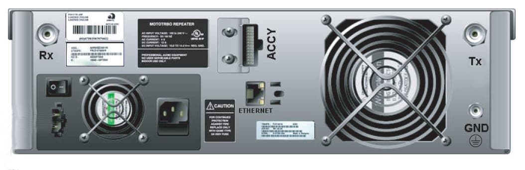
Click to zoom
Application Details
- Equipment Class
- TNB - Licensed Non-Broadcast Station Transmitter
- Date of Grant
- Oct 11, 2007
- Application Purpose
- Original Equipment
- Date of Application
- Oct 11, 2007
- Equipment Note
- MOTOTRBO VHF 25W Transceiver/Repeater
- Frequency Range
- 136.00000000 - 174.00000000
- Company
- Motorola Solutions, Inc.
- Country
- United States
Documents & Files
Document Text
Text extracted from the exhibit documents filed with the FCC. Open a document above to read the original.
Users Manual
i Foreword This manual is intended for use by experienced technicians familiar with similar types of equipment. Specifically, it contains installation information required for the MOTOTRBO XPR 8300 Repeater. For information related to the service of the XPR 8300 Repeater, refer to the list applicable manuals available separately. This list is provided in the Related Publications section on page ii. Product Safety and RF Exposure Compliance See Installation Requirements for Compliance with Radio Frequency (RF) Energy Exposure Safety Standards on page i. Manual Revisions Changes which occur after this manual is printed are described in PMRs (Publication Manual Revisions). These PMRs provide complete replacement pages for all added, changed, and deleted items. To obtain PMRs, go to: http://www.motorola.com/businessonline Parts Ordering See Appendix A: Replacement Parts Ordering for information on how to obtain replacement parts. For part numbers, refer to the XPR 8300 Repeater Basic Service Manual (Motorola publication part number 6816810H01). Computer Software Copyrights The Motorola products described in this manual may include copyrighted Motorola computer programs stored in semiconductor memories or other media. Laws in the United States and other countries preserve for Motorola certain exclusive rights for copyrighted computer programs, including, but not limited to, the exclusive right to copy or reproduce in any form the copyrighted computer program. Accordingly, any copyrighted Motorola computer programs contained in the Motorola products described in this manual may not be copied, reproduced, modified, reverse-engineered, or distributed in any manner without the express written permission of Motorola. Furthermore, the purchase of Motorola products shall not be deemed to grant either directly or by implication, estoppel, or otherwise, any license under the copyrights, patents or patent applications of Motorola, except for the normal non-exclusive license to use that arises by operation of law in the sale of a product. Document Copyrights No duplication or distribution of this document or any portion thereof shall take place without the express written permission of Motorola. No part of this manual may be reproduced, distributed, or transmitted in any form or by any means, electronic or mechanical, for any purpose without the express written permission of Motorola. Disclaimer The information in this document is carefully examined, and is believed to be entirely reliable. However, no responsibility is assumed for inaccuracies. Furthermore, Motorola reserves the right to make changes to any products herein to improve readability, function, or design. Motorola does not assume any liability arising out of the applications or use of any product or circuit described herein; nor does it cover any license under its patent rights nor the rights of others. Trademarks MOTOROLA, the Stylized M logo are registered in the US Patent & Trademark Office. All other product or service names are the property of their respective owners. © 2006, 2007 by Motorola, Inc. i Installation Requirements for Compliance with Radio Frequency (RF) Energy Exposure Safety Standards ATTENTION! This radio is intended for use in occupational/controlled conditions, where users have full knowledge of their exposure and can exercise control over their exposure to meet FCC limits. This radio device is NOT authorized for general population, consumer, or any other use. To ensure compliance to RF Energy Safety Standards: •Install only Motorola approved antennas and accessories •Be sure that Product Safety and RF Safety Booklet enclosed with this radio is available to the end user upon completion of the installation of this radio Before using this product, the operator must be familiar with the RF energy awareness information and operating instructions in the Product Safety and RF Exposure booklet enclosed with each radio (Motorola Publication part number 6881095C99) to ensure compliance with Radio Frequency (RF) energy exposure limits. For a list of Motorola-approved antennas and other accessories, visit the following web site which lists approved accessories for your radio model: http://www.motorola.com/governmentandenterprise ii Declaration of Conformity This declaration is applicable to your radio only if your radio is labeled with the FCC logo shown below. DECLARATION OF CONFORMITY Per FCC CFR 47 Part 2 Section 2.1077(a) Responsible Party Name: Motorola, Inc. Address: 1301 East Algonquin Road, Schaumburg, IL 60196-1078, U.S.A. Phone Number: 1-888-567-7347 Hereby declares that the product: Model Name: XPR 8300 conforms to the following regulations: FCC Part 15, subpart B, section 15.107(a), 15.107(d) and section 15.109(a) Class B Digital Device As a personal computer peripheral, this device complies with Part 15 of the FCC Rules. Operation is subject to the following two conditions: 1. This device may not cause harmful interference, and 2. This device must accept any interference received, including interference that may cause undesired operation. Note:This equipment has been tested and found to comply with the limits for a Class B digital device, pursuant to part 15 of the FCC Rules. These limits are designed to provide reasonable protection against harmful interference in a residential installation. This equipment generates, uses and can radiate radio frequency energy and, if not installed and used in accordance with the instructions, may cause harmful interference to radio communications. However, there is no guarantee that interference will not occur in a particular installation. If this equipment does cause harmful interference to radio or television reception, which can be determined by turning the equipment off and on, the user is encouraged to try to correct the interference by one or more of the following measures: • Reorient or relocate the receiving antenna. • Increase the separation between the equipment and recei…
Text truncated - open the document above for the full version.
Users Manual
June 20076816814H01 Pre-Installation Considerations Site Grounding and Lightning Protection1-3 1.6Site Grounding and Lightning Protection One of the most important considerations when designing a communications site is the ground and lightning protection system. While proper grounding techniques and lightning protection are closely related, the general category of site grounding may be divided into the following section. 1.6.1Electrical Ground Ground wires carrying electrical current from circuitry or equipment at the site is included in the category of electrical ground. Examples include the AC or DC electrical power used to source equipment located at the site, and wires or cables connected to alarms or sensors located at the site. 1.6.2RF Ground This type of ground is related to the transmission of the radio frequency energy to earth ground. An example of RF grounding is the use of shielding to prevent or at least minimize the leakage of unwanted RF transmissions from communications equipment and cables. 1.6.3Lightning Ground Providing adequate lightning protection is critical to a safe reliable communications site. RF transmission cables, and AC and DC power lines must all be protected to prevent lightning energy from entering the site building. Although a comprehensive coverage of the site grounding technique and lightning protection is not within the scope of this instruction manual, there are several excellent industry sources for rules and guidelines on ground and lightning protection at communications site. NOTE:Motorola recommends the following reference source: Motorola Quality Standards Fixed Network Equipment Installation Manual R56................................................................................6881089E50 1.6.4Equipment Grounding Guidelines The repeater is equipped with a ground screw located on the rear of the repeater power supply module. This screw is used to connect the repeater to the site ground point. It is assumed that all antenna cables, and AC or DC power cabling, has been properly grounded and lightning protected by following the rules and guidelines provided in the above reference. 1.7Power Supply Connections Refer to 4.1.1 AC Input Power Connection on page 4-1 for the recommended AC input power connection and to 4.1.2 Ground Connection on page 4-2 for the recommended ground connection. Proper site grounding and lightning protection are vitally important consider- ation. Failure to provide proper lightning protection may result in permanent damage to the radio equipment. ! C a u t i o n June 20076816814H01 1-4Pre-Installation Considerations Notes Chapter 2 Mechanical Installation This section describes the procedures to unpack and mechanically install the MOTOTRBO Repeater. A variety of mounting methods are possible, depending on which type of cabinet or rack (if any) has been selected to house the repeater(s). Installation procedures are provided for each of the cabinet and rack types. 2.1Unpacking Equipment 2.2Transferring Equipment from Shipping Container to Rack or Cabinet The repeater is shipped in a box. Upon delivery, the equipment must be removed from the container and transferred to a rack or cabinet. NOTE:Customer-supplied cabinets and racks must have mounting rail and hole spacing compatible with EIA Universal 48.3 cm (19 inches) specifications. Cabinets must provide adequate ventilation (as detailed on page 3) and must meet the following criteria: - 41.3 cm (16.25 inches) deep - 48.3 cm (19 inches) wide - 13.4 cm (5.25 inches) high Two mounting rails 5 cm (2 inches) from front cabinet with front mounting holes 5.7 cm (2.25 inches) apart (center to center). Contact Motorola Technical Support for specific question(s) regarding mounting equipment in customer-supplied cabinets. Be sure to observe proper electrostatic discharge precautions if modules must be removed from the repeater. Inspect the equipment for damage immediately after unpacking, and make a report of the extent of any damage to the transportation company and to Motorola. ! C a u t i o n ! W A R N I N G ! June 20076816814H01 Notes 2-2Mechanical Installation Chapter 3 Indicators and Connectors 3.1Front Panel 3.1.1LED Indicator Descriptions LEDStatusDescription Power Solid GREENRepeater powered by AC Solid REDRepeater powered by backup battery OffRepeater powered off Repeater Disable Solid REDRepeater function disabled Blinking REDRepeater in self-test mode OffRepeater in normal operational mode Digital Solid BLUERepeater in Digital Mode AnalogSolid YELLOWRepeater in Analog Mode Tx-A Solid GREENRepeater transmitting (Analog) Solid GREENRepeater transmitting on Slot A (Digital) Rx-A Solid YELLOWRepeater receiving a signal for Slot A (Analog) Solid YELLOWRepeater receiving on Slot B (Digital) Tx-BSolid GREEN Repeater transmitting on Slot B (Digital) Rx-BSolid YELLOWRepeater receiving a signal for Slot B (Digital) June 20076816814H01 3-2Indicators and Connectors 3.2Rear Panel 3.2.1Rear Panel Parts NoItemDescription Rx ConnectorType BNC-F Power Supply On/Off Switch Turns on or off the power to the repeater from AC input. Battery Backup Connector (DC Input) Backup battery supplies backup power to the repeater. The battery is an optional accessory. The repeater will trickle charge battery, but an external charger is recommended to equalize battery after a prolonged use. Auto switching from AC to battery with loss of AC power is a function of the standard repeater power supply. Supply will automatically switch back to AC operation upon the return of AC power. The front panel power LED switches from green to red when on battery power. Power Supply FanRuns continuously. Main Power Supply Connector (AC Input) 100 – 240 Volts 26-Pin Accessory Connector Programming cable plugs in here. Ethernet Connector(For Future Use) Main Fan Variable speed. Idles at room temperature. Speeds up with extended use of the repeater. Tx ConnectorType N – F Ground ScrewMust be connected to System Ground. 1 3 …
Text truncated - open the document above for the full version.
Cover Letter(s)
FCC ID: ABZ99FT3026 Date: Oct. 9, 2007 Authorization & Evaluation Division Federal Communications Commission Laboratory 7435 Oakland Mills Road Columbia, MD 21046 Subject: Application for Certification of Transmitter with FCC ID: ABZ99FT3026 Dear Sir or Madam: Motorola Inc., 1313 East Algonquin Road, Schaumburg, Illinois, herein submits application for Certification of the 25 Watt VHF repeater identified by FCC ID number ABZ99FT3026. This transmitter is primarily intended for use in a Repeater application with capabilities for conventional and 2 to 1 TDMA digital communications with a conducted transmit power which is adjustable from 1 Watt to 25 Watts. The subject transmitter complies with CFR Title 47, Section 90.203, in that the operator cannot directly program the transmit frequencies using only the normally accessible external controls of the unit. Enclosed is a complete Certification Application. Please contact me if you require any additional information. Sincerely, /s/Larry D. Larsen(signed) Larry D. Larsen Engr. Sec Mgr. Tel: (847)-538-2239 Fax: (847)-538-4312 E-mail: [email protected]
Cover Letter(s)
FCC ID: ABZ99FT3026 REQUEST FOR CONFIDENTIALITY Date: Oct. 9, 2007 Authorization & Evaluation Division Federal Communications Commission Laboratory 7435 Oakland Mills Road Columbia, MD 21046 Subject: Application for Certification of Transmitter with FCC ID: ABZ99FT3026 Dear Sir or Madam: Motorola is requesting that Circuit Descriptions, Schematic Diagrams, Parts List and Tune Up Procedures, and Operational Description not be made routinely available for public inspection. Motorola considers the information in these exhibits to be classified as trade secrets, pursuant to 47 CFR Section 0.457(d) and Section 552(b)(4) of the Freedom of Information Act. Please contact me if you require any additional information. Sincerely, /s/Larry D. Larsen(signed) Larry D. Larsen Engr. Sec. Mgr Tel: (847)-538-2239 Fax: (847)-538-4312 E-mail: [email protected]
Cover Letter(s)
FCC ID: ABZ99FT3026 Date: Oct. 2, 2007 Authorization & Evaluation Division Federal Communications Commission Laboratory 7435 Oakland Mills Road Columbia, MD 21046 Subject: Application for Extended Frequencies for Transmitter with FCC ID: ABZ99FT4026 Dear Sir or Madam: Motorola Inc., 1313 East Algonquin Road, Schaumburg, Illinois, herein requests grant for extended frequencies within the range of FCC Rule P art 90 for the 25 Watt VHF repeater identified by FCC ID:ABZ99FT3026. The repeater is designed to operate in the 136 to 174 MHz band and we request the grant for contigious range of 136-174 MHz. This repeater will also be marketed to elements of the US Federal government (NTIA), exported to Canada and other international markets. For the United States market, the radios will be programed on authorized frequencies that are licensed by the FCC. This repeaterter complies with CFR Title 47, Section 90.203, in that the operator cannot directly program the transmit frequencies using only the normally accessible external controls of the unit. The transmitter programming is the responsibility of authorized dealers and service agents. Please contact me if I can be of assistance. Sincerely, /s/Larry D. Larsen(signed) Larry D. Larsen Engr. Section Mgr. Tel: (847)-538-2239 Fax: (847)-538-4312 E-mail: [email protected] Deleted: beyong Deleted: beyond p Deleted: number Deleted: Deleted: nuouscontinuous Deleted: .0 Deleted: to 470.0MHz.
External Photos
MOTOROLA INC FCC ID: ABZ99FT3026 /IC: 109AB-99FT3026 GENERAL VIEW MOTOROLA INC FCC ID: ABZ99FT3026 /IC: 109AB-99FT3026 FRONT VIEW FCC Label REAR VIEW, SHOWING FCC ID LABEL (CLOSE-UP OF FCC ID LABEL ON FOLLOWING PAGE) MOTOROLA INC FCC ID: ABZ99FT3026 /IC: 109AB-99FT3026 CLOSE-UP VIEW OF FCC ID LABEL
ID Label/Location Info
MOTOROLA INC FCC ID: ABZ99FT3026 /IC: 109AB-99FT3026 IDENTIFICATION LABEL Pursuant to 47 CFR 2.1033(c) LOCATION A nameplate of the type presented below will be affixed to every transmitter. It will be placed on the left rear portion of the unit. Shown below is a photo of the actual label affixed to the cast chassis of the transmitter. TYPE The label is a paper polyester film laminated with a pressure sensitive adhesive backing. The adhesive is a permanent type acrylic with a minimum peel strength of 40 oz/inch. MOTOROLA INC FCC ID: ABZ99FT3026 /IC: 109AB- 99FT3026 GENERAL INFORMATION 1. Production Plans – Pursuant 2.1033 (c) Quantity production is planned. 2. Application References: TIA/EIA-603 Land Mobile FM or PM Communications Equipment Measurement and Performance Standards Code of Federal Regulations Title 47, Part 2, Sec. 2.1033-2.1057, and Part 90 Sec. 90.210. 3. Data Submittal Procedure: Data is supplied in accordance with Part 2, Sub-part J of the Commissions’ rules. The intended use of this transceiver includes applications covered in the Code of Federal Regulations Title 47, Part 90. Maximum transmitter power shall not be adjustable by the user.
Internal Photos
MOTOROLA INC FCC ID: ABZ99FT3026 /IC: 109AB-99FT3026 TOP VIEW OF WITH TOP COVER REMOVED MOTOROLA INC FCC ID: ABZ99FT3026 /IC: 109AB-99FT3026 TOP VIEW WITH RADIO CIRCUIT BOARD REMOVED FROM CHASSIS (MATING SURFACES OF CIRCUIT BOARD AND CHASSIS ARE SHOWN) MOTOROLA INC FCC ID: ABZ99FT3026 /IC: 109AB-99FT3026 TOP VIEW OF FRONT PANEL LED BOARD MOTOROLA INC FCC ID: ABZ99FT3026 /IC: 109AB-99FT3026 TOP VIEW OF BACK PANEL BOARD
Test Report
Engineering Test Report No. 38720-01 Measurement of RF Interference from a Model AAM27JNR9JA7AN, Cypher Repeater For : Motorola Inc. Rolling Meadows, IL 60008 P.O. No. : NP 3535176 Date Received : August 14, 2007 Date Tested : August 14 through September 6, 2007 Test Personnel: Richard E. King Specification : FCC "Code of Federal Regulations” Title 47 Part 15, Subpart B and Part 90, Subpart I RSS-119 - Land Mobile and Fixed Radio Transmitters and Receivers Operating in The Frequency Range 27.41- 960 MHz Test Report By : Richard E. King Witnessed By : Skip Allison Motorola Inc. Approved By : Raymond J. Klouda Registered Professional Engineer of Illinois - 44894 Elite Electronic Engineering Inc. 1516 Centre Circle Downers Grove, IL 60515 Tel : (630) 495-9770 Fax: (630) 495-9785 www.elitetest.com Engineering Test Report No. 38720-01 THIS REPORT SHALL NOT BE REPRODUCED, EXCEPT IN FULL, WITHOUT THE WRITTEN APPROVAL OF ELITE ELECTRONIC ENGINEERING INCORPORATED. Page 2 of 137 TABLE OF CONTENTS PARAGRAPH DESCRIPTION OF CONTENTS PAGE NO. 1.0 INTRODUCTION............................................................................................................................................... 5 1.1 Description of Test Item................................................................................................................................5 1.2 Purpose.......................................................................................................................................................... 5 1.3 Deviations, Additions and Exclusions.......................................................................................................... 5 1.4 Applicable Documents.................................................................................................................................. 5 1.5 EMC Laboratory Identification...................................................................................................................... 6 1.6 Laboratory Conditions................................................................................................................................. 6 2.0 TEST ITEM SETUP AND OPERATION.......................................................................................................... 6 2.1 Power Input.................................................................................................................................................... 6 2.2 Grounding....................................................................................................................................................... 6 2.3 Peripheral Equipment.................................................................................................................................... 6 2.4 Interconnect Cables...................................................................................................................................... 6 2.5 Operational Mode.......................................................................................................................................... 6 2.6 Test Item Modifications...............................................................................................................................7 3.0 TEST EQUIPMENT........................................................................................................................................... 7 3.1 Test Equipment List....................................................................................................................................... 7 3.2 Calibration Traceability................................................................................................................................7 3.3 Measurement Uncertainty........................................................................................................................... 7 4.0 REQUIREMENTS, PROCEDURES AND RESULTS.................................................................................... 7 4.1 Receiver........................................................................................................................................................ 7 4.1.1 Powerline Conducted Emissions...................................................................................................... 7 4.1.1.1 Requirements................................................................................................................................7 4.1.1.2 Procedures.................................................................................................................................... 8 4.1.2 Antenna Conducted Emissions Measurements............................................................................... 8 4.1.2.1 Requirements................................................................................................................................8 4.1.2.2 Procedures..................................................................................................................................... 8 4.1.2.3 Results............................................................................................................................................ 9 4.1.3 Radiated Measurements..................................................................................................................... 9 4.1.3.1 Requirements................................................................................................................................9 4.1.3.2 Procedures..................................................................................................................................... 9 4.1.3.3 Results.......................................................................................................................................... 10 4.2 Transmitter.................................................................................................................................................. 10 4.2.1 R…
Text truncated - open the document above for the full version.
Contact Information
Applicant
Matthew Nawrocki
Technical Contact
Motorola, IncLarry Larsen
[email protected]18475382239
1313 East Algonquin Road · Schaumburg, Illinois · United States
Non-Technical Contact
Motorola, IncDonna Tokarz
[email protected]18475387245
Test Firm
Elite Electronic Engineering Inc.Kevin Halpin
Technical Specifications
| # | Rule Parts | Frequency Range | Power Output | Emission | Tolerance |
|---|---|---|---|---|---|
| 4 | 90,9 | 136 MHz - 174 MHz | 25 W | 7K60FXE | 1.5 ppm |
Other Applications from Motorola Solutions, Inc.

ABZ89FT4940
Aug 06, 2026Non Broadcast Transmitter
Equipment Class
TNB - Licensed Non-Broadcast Station TransmitterABZ89FT4950
Jun 25, 2026Non-Broadcast Transmitter
Equipment Class
TNB - Licensed Non-Broadcast Station TransmitterABZ89FT5901
Jun 20, 2024Non Broadcast Transmitter
Equipment Class
TNB - Licensed Non-Broadcast Station Transmitter
ABZ99FT5101B
May 02, 2023Non Broadcast Transmitter
Equipment Class
PCB - PCS Licensed Transmitter
ABZ99FT3095B
Mar 26, 2023Non Broadcast Transmitter
Equipment Class
TNB - Licensed Non-Broadcast Station Transmitter