ABZ99FT3050VHF Portable Handheld Transceiver
Motorola Solutions, Inc.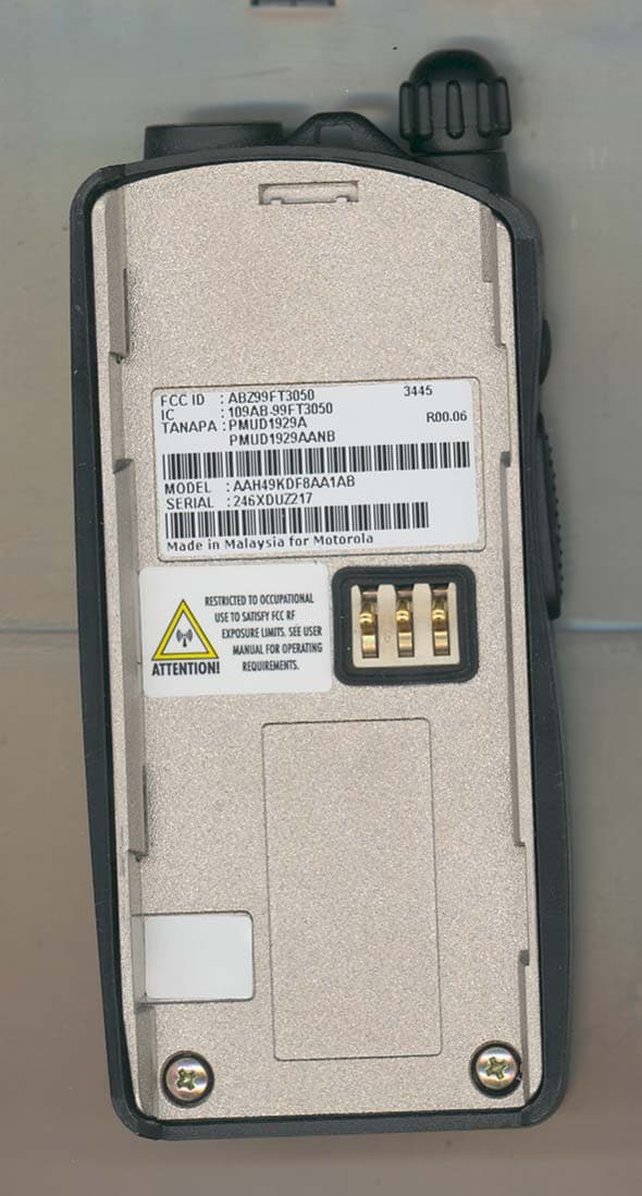
Click to zoom
Application Details
- Equipment Class
- TNF - Licensed Non-Broadcast Transmitter Held to Face
- Date of Grant
- Jan 08, 2004
- Application Purpose
- Original Equipment
- Date of Application
- Nov 24, 2003
- Equipment Note
- VHF Portable Handheld Transceiver
- Frequency Range
- 136.00000000 - 174.00000000
- Company
- Motorola Solutions, Inc.
- Country
- United States
Documents & Files
Document Text
Text extracted from the exhibit documents filed with the FCC. Open a document above to read the original.
Users Manual
English Product Safety and RF Exposure for Portable Two-Way Radios The information provided in this document supersedes the general safety information contained in user guides published prior to February 2002. For radios that have been approved as intrinsically safe, read the instructions and information on intrinsic safety on page 9 of this booklet. Compliance with RF Energy Exposure Standards NOTICE: This radio is intended for use in occupational/controlled applications where users have been made aware of the potential for exposure and can exercise control over their exposure. This radio device is NOT authorized for general population, consumer or similar use. BEFORE USING THIS RADIO, READ THIS BOOKLET WHICH CONTAINS IMPORTANT OPERATING INSTRUCTIONS FOR SAFE USAGE AND RF ENERGY AWARENESS AND CONTROL INFORMATION FOR COMPLIANCE WITH RF ENERGY EXPOSURE LIMITS IN APPLICABLE NATIONAL AND INTERNATIONAL STANDARDS. ! C a u t i o n © Motorola, Inc. 2003 8000 W. Sunrise Blvd., Ft. Lauderdale, FL 33322 Printed in U.S.A. 3/03. *6881095C98* 68P81095C98-A 2 English Federal Communication Commission (FCC) Regulations The FCC has established limits for safe exposure to radio frequency (RF) emissions from portable two-way radios. The FCC requires manufacturers to demonstrate compliance with RF exposure limits before portable two-way radios can be marketed in the U.S. When two-way radios are approved for occupational/ controlled environment exposure limits, the FCC requires users to be fully aware of, and exercise control over, their exposure. Awareness and control of RF exposure can be accomplished by the use of labels, or by education and training through appropriate means, such as information and instructions in user manuals or safety booklets. Your Motorola two-way radio has an RF exposure information label in the battery compartment. This user safety booklet includes useful information about RF exposure and helpful instructions on how to control your RF exposure. Your Motorola two-way radio is designed and tested to comply with a number of national and international standards and guidelines (listed below) regarding human exposure to RF electromagnetic energy. This radio complies with the IEEE (FCC) and ICNIRP exposure limits for occupational/controlled RF exposure environments at usage factors of up to 50% talk–50% listen. In terms of measuring RF energy for compliance with FCC exposure guidelines, your radio radiates measurable RF energy only while it is transmitting (during talking), not when it is receiving (listening) or in standby mode. NOTE:The approved batteries, supplied with this radio, are rated for a 5-5-90 duty cycle (5% talk–5% listen–90% standby), even though this radio complies with FCC occupational exposure limits at usage factors of up to 50% talk. 3 English Your Motorola two-way radio complies with the following RF energy exposure standards and guidelines: • United States Federal Communications Commission, Code of Federal Regulations; 47CFR part 2 sub-part J • American National Standards Institute (ANSI) / Institute of Electrical and Electronic Engineers (IEEE) C95. 1-1992 • Institute of Electrical and Electronic Engineers (IEEE) C95.1-1999 Edition • International Commission on Non-Ionizing Radiation Protection (ICNIRP) 1998 • Ministry of Health (Canada) Safety Code 6. Limits of Human Exposure to Radiofrequency Electromagnetic Fields in the Frequency Range from 3 kHz to 300 GHz, 1999 • Australian Communications Authority Radiocommunications (Electromagnetic Radiation – Human Exposure) Standard, 2001 • ANATEL, Brasil Regulatory Authority, Resolution 256 (April 11, 2001) “additional requirements for SMR, cellular and PCS product certification.” Compliance and Control Guidelines and Operating Instructions for Portable Two-Way Radios To control your exposure and ensure compliance with the occupational/ controlled environment exposure limits, always adhere to the following procedures: • Transmit no more than 50% of the time. To transmit (talk), push the Push- To-Talk (PTT) button. To receive calls, release the PTT button. Transmitting 50% of the time or less is important since the radio generates measurable RF energy exposure only when transmitting (in terms of measuring standards compliance). 4 English • Hold the radio in a vertical position in front of the face with the microphone (and other parts of the radio including the antenna) at least one to two inches (2.5 to 5 centimeters) away from the lips. Keeping the radio at a proper distance is important since RF exposures decrease with increasing distance from the antenna. •For body-worn operation, always place the radio in a Motorola-approved clip, holder, holster, case, or body harness for this product. All Motorola- approved accessory, antenna, and device combinations comply with FCC occupational/controlled environment RF exposure limits. Exposure information on various accessory, antenna, and device combinations can be found under the “Display Exhibits” section of http://www.fcc.gov/oet/ fccid after searching on the FCC ID number, which can be obtained from the label of your radio. Using non–Motorola-approved accessories may result in exposure levels which exceed the FCC’s occupational/controlled environment RF exposure limits. • If you are not using a body-worn accessory and are not using the radio in the intended use position in front of the face, ensure the antenna and the radio are kept one inch (2.5 centimeters) from the body when transmitting. Keeping the radio at a proper distance is important since RF exposures decrease with increasing distance from the antenna. •Use only Motorola-approved supplied or replacement antennas, batteries, and accessories. Use of non–Motorola-approved antennas, batteries and accessories may exceed FCC RF exposure guidelines. For a list of Motorola- approved antennas, batteries, and other accessories, visit the following web site which lists approved accessories: http://www.motorola.com/cgiss/inde…
Text truncated - open the document above for the full version.
Attestation Statements
Applicant: Motorola Inc. FCC ID: ABZ99FT3050 Certification of Data Pursuant to 47 CFR 2.1517(g) The technical data supplied with this application, having been taken under my supervision is hereby duly certified. The following is a statement of my qualifications: 1) I received a BEEE degree from the University of Technology , Malaysia. 2) I have 5 years experience in developing, testing, and certifying Land Mobile Communications Products. NAME: Sumiyyah Abdul Kader SIGNATURE: SUMIYYAH DATE: November 25, 2003 POSITION: Electrical Engineer I hereby certify that the above application was prepared under my direction and that to the best of my knowledge and belief, the facts set forth in the application and accompanying technical data are true and correct. NAME: Muhammad Azanor SIGNATURE: AZANOR DATE: November 25, 2003 POSITION: Engineering Manager EXHIBIT 2 SHEET 1 OF 1
Cover Letter(s)
Applicant: Motorola Inc FCC ID: ABZ99FT3050 Table of Contents EXHIBIT 1. IDENTIFICATION LABEL -- 47 CFR. 2.925, 2.1065 & 2.1033(C) (11)....................................... 1-1 EXHIBIT 1A. GENERAL INFORMATION.............................................................................................. 1-2 1A.1. Application References.................................................................................................................. 1-2 1A.2. Data Submittal Procedure............................................................................................................... 1-2 1A.3. Similar, currently Type Accepted Transmitter...................................................................................... 1-2 EXHIBIT 2. STATEMENT OF CERTIFICATION -- 47 CFR. 2.907.........................................................................2-1 EXHIBIT 3. EXTERNAL PHOTOGRAPHS -- Pursuant 47 CFR 2.1033 (C )12......................................................3-1 EXHIBIT 4. CIRCUIT DESCRIPTION-----47 CFR. 2.1033(C)10.............................................................................4-1 4A. Carrier Frequency Generation and Stabilization..................................................................................... 4-1 4B. Means for Limiting Modulation ........................................................................................................... 4-1 4C. Means of Attenuation of Higher Audio Frequencies................................................................................ 4-1 4D. Means for Attenuation of Spurious Emissions....................................................................................... 4-1 4E. Means for Limiting Output Power........................................................................................................ 4-1 4F. Modulation Techniques..................................................................................................................... 4-2 4G. Means for Controlling Transient Frequency Behavior.............................................................................. 4-2 4H. Block Diagrams.............................................................................................................................. 4-3 EXHIBIT 5. CIRCUIT DIAGRAMS-- Pursuant 47 CFR 2.1033(C)10......................................................................5-1 EXHIBIT 6. MEASURED DATA-----47 CFR. 2.1041 & 2.1033 (c) (14).................................................................. 6-1 6A. RF Power -- Pursuant 47 CFR 2.1046(a) & 2.1033(c)8 .......................................................................... 6-2 6B. Transmit Audio Frequency Resp on se-- Pursuant to 47 CFR 2.1047(a)...................................................... 6-3 6C. Transmit Audio Post Limiter Lowpass Filter Response-- Pursuant to 47 CFR 2.1047(a)................................ 6-4 6D. Modulation Characteristics Data -- Pursuant 47 CFR 2.1047 (d)............................................................... 6-5 6E. Occupied Bandwidth Data -- Pursuant 47 CFR 2.1049(i), 90.210(b) (d )..................................................... 6-8 6F. Conducted Spurious Emissions Data-- Pursuant 47 CFR 2.1051, 2.1057................................................... 6-11 6G. Radiated Spurious Emission s Data -- Pursuant 47 CFR 2.1053, 2.1057.................................................... 6-14 6H. Frequency Stability Data -- Pursuant 47 CFR 2.1055(a)(d)..................................................................... 6-17 6I. Transient Frequen cy Behavior -- Pursuant to 47 CFR 90.214.................................................................. 6-18 EXHIBIT 7. MEASUREMENT PROCEDURES-----47 CFR. 2.947.......................................................... 7-1 7A. RF Power -- Pursuant to 47 CFR 2.1046............................................................................................. 7-1 7B. Transmit Audio Frequency Response-- Pursuant to 47 CFR 2.1047(a)...................................................... 7-1 7C. Transmit Audio Post Limiter Lowpass Filter Response-- Pursuant to 47 CFR 2.1047(a)................................ 7-1 7D. Modulation Characteristics Data -- Pursuant 47 CFR 2.1047 (d)............................................................... 7-1 7E. Occupied Bandwidth -- Pursuant to 47 CFR 2.1049(c)(i)......................................................................... 7-1 7F. Conducted Spurious Emissions--Pursuant to 47 CFR 2.1051................................................................... 7-2 7G. Radiated Spurious Emissions -- Pursuant to 47 CFR 2.1053................................................................... 7-2 7H. Frequency Stability -- Pursuant to 47 CFR 2.1055(a)(d).......................................................................... 7-3 7I. Transient Frequency Behavior -- Pursuant to 47 CFR 90.214 and TIA 603 Section 2.2.19.............................. 7-3 7J. Measurement Equipment List -- Pursuant to 47 CFR 2.947(d).................................................................. 7-4 EXHIBIT 8. USER INSTRUCTION MANUAL-- Pursuant 47 CFR 2.1033(C)3 ..................................................... 8-1 EXHIBIT 9. INTERNAL PHOTOGRAPHS-- Pursuant 47 CFR 2.1033(C)12........................................................ 9-1 EXHIBIT 0 Applicant: Motorola Inc FCC ID: ABZ99FT3050 EXHIBIT 0 EXHIBIT 10. SEMICONDUCTOR/ACTIVE DEVICE LIST AND TUNE UP PROCEDURE .................................. 10-1 10A. Semiconductor / Active Device List -- 47 CFR 2.1033(c)(10) 10-1 10B. List of Recommended Test Equipment for Servicing -- 47 CFR 2.1033(c)(10)......................................... 10-4 10C. Tune Up Procedure -- 47 CFR 2.1033-(c)(9).................................................................................... 10-5 EXHIBIT 11. RF EXPOSURE INFORMATION-- Pursuant 47 CFR 2.1091.......................................................... 11-1…
Text truncated - open the document above for the full version.
Cover Letter(s)
FCC ID: ABZ99FT3050 Date: November 25, 2003 Authorization & Evaluation Division Federal Communications Commission Laboratory 7435 Oakland Mills Road Columbia, MD 21046 Subject: Application for Certification of Transmitter with FCC ID: ABZ99FT3050 Dear Sir or Madam: Motorola Inc., 1313 East Algonquin Road, Schaumburg, Illinois, herein submits application for Certification of the equipment identified by FCC ID number ABZ99FT3050. This transmitter is primarily intended for use in a portable radio application with capabilities for conventional communications with a conducted transmit power which is adjustable from 2 Watt (+33 dBm) to 5.7 Watts (+37.6 dBm). The subject transmitter complies with CFR Title 47, Section 90.203, in that the operator cannot directly program the transmit frequencies using only the normally accessible external controls of the unit. Enclosed is a complete Certification Application. Please contact me if you require any additional information. Sincerely, Donna Tokarz NPR Coordinator Tel: (847) 576-7245 Fax: (847) 538-4312 E-mail: [email protected] EXHIBIT 13A SHEET 1 OF 1
Cover Letter(s)
FCC ID: ABZ99FT3050 REQUEST FOR CONFIDENTIALITY Date: November 25, 2003 Authorization & Evaluation Division Federal Communications Commission Laboratory 7435 Oakland Mills Road Columbia, MD 21046 Subject: Application for Certification of Transmitter with FCC ID: ABZ99FT3050 Dear Sir or Madam: Motorola is requesting that Exhibit 4 (Circuit Descriptions), Exhibit 5 (Schematic Diagrams), Exhibit 10 (Parts List and Tune Up Procedures), and Exhibit 12 (Operational Description) not be made routinely available for public inspection. Motorola considers the information in these exhibits to be classified as trade secrets, pursuant to 47 CFR Section 0.457(d) and Section 552(b)(4) of the Freedom of Information Act. Please mark Exhibits 4, 5, 10, and 12 as “Confidential.” Please contact me if you require any additional information. Sincerely, Donna Tokarz NPR Coordinator Tel: (847) 576-7245 Fax: (847) 538-4312 E-mail: [email protected] EXHIBIT 13B SHEET 1 OF 1
External Photos
Applicant: Motorola Inc. FCC ID: ABZ99FT3050 External Photographs Pursuant to 47 CFR 2.1033(c) 12 Figure 3-1: Front view of complete radio. EXHIBIT 3 SHEET 1 OF 6 Applicant: Motorola Inc. FCC ID: ABZ99FT3050 Figure 3-2: Back view of complete radio. EXHIBIT 3 SHEET 2 OF 6 Applicant: Motorola Inc. FCC ID: ABZ99FT3050 Figure 3-3: Right side view of complete radio. EXHIBIT 3 SHEET 3 OF 6 Applicant: Motorola Inc. FCC ID: ABZ99FT3050 Figure 3-4: Left side view of complete radio. EXHIBIT 3 SHEET 4 OF 6 Applicant: Motorola Inc. FCC ID: ABZ99FT3050 FCC Label Location RF Safety Label Location Figure 3-5: Rear view of complete radio showing FCC Label & RF Safety Label location. EXHIBIT 3 SHEET 5 OF 6 Applicant: Motorola Inc. FCC ID: ABZ99FT3050 EXHIBIT 3 SHEET 6 OF 6 Figure 3-6: Close-up of RF Safety Label Stubby Antenna Heliflex Antenna Figure 3-7: Types of Antenna
ID Label/Location Info
Applicant: Motorola Inc. FCC ID: ABZ99FT3050 IDENTIFICATION LABEL Pursuant to 47 CFR 2.925(a), 2.1033(c), 2.0165 LOCATION A nameplate of the type presented below will be affixed to every transmitter. It will be placed on the bottom of the unit near the front. Shown below is a photo of the actual label affixed to the cast chassis of the transmitter. TYPE The label is a paper polyester film laminate with a pressure sensitive adhesive backing. The adhesive is a permanent type acrylic with minimum peel strength of 40 oz/inch. EXHIBIT 1 SHEET 1 OF 2 Applicant: Motorola Inc. FCC ID: ABZ99FT3050 EXHIBIT 1 SHEET 2 OF 2 EXHIBIT 1A – GENERAL INFORMATION 1. Application References: TIA/EIA-603 Land Mobile FM or PM Communications Equipment Measurement and Performance Standards Code of Federal Regulations Title 47, Part 2, Sec. 2.1033-2.1057, and Part 90, Section 90.210. 2. Data Submittal Procedure: Data is supplied in accordance with Part 2, Sub-part J of the Commission’s rules. The intended use of this transceiver includes applications covered in the Code of Federal Regulations Title 47, Parts 80 and 90. Maximum transmitter power shall not be adjustable by the user.
Internal Photos
Applicant: Motorola Inc. FCC ID: ABZ99FT3050 Internal Photographs Pursuant to 47 CFR 2.1033(c)12 Figure 9-1: Top Side of RF PCB. Figure 9-2: Bottom Side of RF PCB. EXHIBIT 9 SHEET 1 OF 3 Applicant: Motorola Inc. FCC ID: ABZ99FT3050 Figure 9-3: Top Side of Controller PCB. Figure 9-4: Bottom Side of Controller PCB with shields. EXHIBIT 9 SHEET 2 OF 3 Applicant: Motorola Inc. FCC ID: ABZ99FT3050 EXHIBIT 9 SHEET 3 OF 3 Figure 9-5: Top View of chassis. Figure 9-6: Bottom View of chassis.
RF Exposure Info
APPLICANT: MOTOROLA INC. FCC ID: ABZ99FT3050 RF EXPOSURE INFORMATION Pursuant 47 CFR 2.1093 In accordance with 47 CFR 2.1093(c) this transmitter has been subjected to routine environmental evaluation for RF exposure and found to be compliant with the limits specified in 47 CFR 2.1093(d) for portable devices, using measurements per methods stated in 47 CFR 2.1093(d)(3). The complete S.A.R. EME Compliance Test Report is attached as Exhibit 11B. EXHIBIT 11A SHEET 1 OF 1
RF Exposure Info
CGISS EME Form-SAR-Rpt-Rev. 2.00 Page 1 of 22 CGISS EME Test Laboratory 8000 West Sunrise Blvd Fort Lauderdale, FL. 33322 S.A.R. EME Compliance Test Report Part 1 of 3 Note: Based on the information and the testing results provided herein, the undersigned certifies that when used as stated in the operating instructions supplied, said product complies with all applicable national and international reference standards and guidelines. Deanna Zakharia Signature on File 11/20/03 ____________________________________________________________ _________________________ Ken Enger Date Approved Senior Resource Manager, Product Safety and EME Director, Phone: 954-723-6299 Note: Consistent with the ISO/IEC 17025 recommendation this report shall not be reproduced in part without written approval from an officially designated representative of the Motorola EME Laboratory. Date of Report: November 20, 2003 Report Revision: Rev. O Manufacturer: Motorola Product Description: Portable 136-174 MHz, 5W, 32 CH w/ display/Limited Keypad FCC ID: ABZ99FT3050 Device Model: PMUD1928A Certificate Number: 1449-02 Test Period: 11/6/03 – 11/13/03 EME Technician: Ed Church Responsible Engineer: Kim Uong (Sr. EME Engineer) Author: Michael Sailsman Global EME Regulatory Affairs Liaison CGISS EME Form-SAR-Rpt-Rev. 2.00 Page 2 of 22 TABLE OF CONTENTS Part 1 of 3 1.0 Introduction 2.0 Reference Standards and Guidelines 3.0 Description of Test Sample 3.1 Test Signal 3.2 Test Output Power 4.0 Description of Test Equipment 4.1 Description of S.A.R Measurement System 4.2 Description of Phantom 4.2.1 Flat Phantom 4.2.2 SAM phantom 4.3 Simulated Tissue Properties 4.3.1 Type of Simulated Tissue 4.3.2 Simulated Tissue Composition 4.4 Test condition 5.0 Description of Test Procedure 5.1 Device Test Positions 5.1.1 Body 5.1.2 Head 5.1.3 Face 5.2 Test Position Photographs 5.3 Probe Scan Procedures 6.0 Measurement Uncertainty 7.0 S.A.R. Test Results 7.1 S.A.R. results 7.2 Peak S.A.R. location 7.3 Highest S.A.R. results calculation methodology 8.0 Conclusion Part 2 of 3 Appendix A: Power Slump Data/Shortened scan Appendix B: Data Results Appendix C: Dipole System Performance Check Results Part 3 of 3 Appendix D: Calibration Certificates Appendix E: Illustration of Body-worn Accessories Appendix F: Accessories and options test status and separation distances CGISS EME Form-SAR-Rpt-Rev. 2.00 Page 3 of 22 REVISION HISTORY Date Revision Comments 11/20/03 O Release of Pilot results CGISS EME Form-SAR-Rpt-Rev. 2.00 Page 4 of 22 1.0 Introduction This report details the utilization, test setup, test equipment, and updated test results of the Specific Absorption Rate (S.A.R.) measurements performed at the CGISS EME Test Lab for model number PMUD1928A, FCC ID: ABZ99FT3050. The applicable exposure environment is Occupational/Controlled. 2.0 Reference Standards and Guidelines This product is designed to comply with the following national and international standards and guidelines. • United States Federal Communications Commission, Code of Federal Regulations; 47CFR part 2 sub-part J • IEEE 1528, 2003 "Recommended Practice for Determining the Peak Spatial-Average Specific Absorption Rate (SAR) in the Human Head from Wireless Communications Devices: Measurement Techniques," • American National Standards Institute (ANSI) / Institute of Electrical and Electronic Engineers (IEEE) C95. 1-1992 • Institute of Electrical and Electronic Engineers (IEEE) C95.1-1999 Edition • International Commission on Non-Ionizing Radiation Protection (ICNIRP) 1998 • Ministry of Health (Canada) Safety Code 6. Limits of Human Exposure to Terminal frequency Electromagnetic Fields in the Frequency Range from 3 kHz to 300 GHz, 1999 • Australian Communications Authority Radiocommunications (Electromagnetic Radiation - Human Exposure) Standard 2003 • ANATEL, Brazil Regulatory Authority, Resolution 256 (April 11, 2001) "additional requirements for SMR, cellular and PCS product certification." CGISS EME Form-SAR-Rpt-Rev. 2.00 Page 5 of 22 3.0 Description of Test Sample The portable handheld transceiver, FCC ID: ABZ99FT3050, operates using Frequency Modulation (FM) incorporating traditional simplex two-way radio transmission protocol. The intended operating positions are “at the face” with the DUT 1 to 2 inches from the mouth, and “at the body” by means of the offered body-worn accessories. Audio and PTT operation while the radio is at the body is accomplished by means of optional remote accessories that connect to the radio. This device will be marketed to and used by employees solely for work-related operations, such as public safety agencies, e.g. police, fire and emergency medical. User training is the responsibility of these agencies, which can be expected to employ the usage instructions, safety information and operational cautions set forth in the user's manual, instructional sessions or other means. Motorola also makes available to its customers training classes on the proper use of two-way radios and wireless data devices. FCC ID: ABZ99FT3050 is capable of operating in the 136-174 MHz band. The rated power is 5 watts with a maximum output capability of 5.7 watts as defined by the upper limit of the production line final test station. CGISS EME Form-SAR-Rpt-Rev. 2.00 Page 6 of 22 FCC ID: ABZ99FT3050 is offered with the following options and accessories: Antenna PMAD4027A Helical 136-155 MHz antenna; -10dBd PMAD4028A Helical 148-174 MHz antenna; -10dBd PMAD4012A Helical 136-155 MHz antenna; -12dBd PMAD4013A Helical 155-174 MHz antenna; -12dBd PMAD4014A Helical 136-155 MHz antenna; -10dBd PMAD4015A Helical 155-174 MHz antenna; -10dBd NAD6502AR Heliflex 146-174 MHz antenna; -4dBd Batteries PMNN4046A Std. NiMH battery Body-worn Accessories 4285820Z01 Shoulder Strap HLN9844A Belt Clip (1.5” belt width) PMLN4467A Carry case, Soft Leather Black PMLN4468A Carry Holster Case, Neoprene Grey PMLN4469A Carry Holster Case, Neoprene Blue RLN4815A Fanny Pack Carry Accessory HLN9985B Waterproo…
Text truncated - open the document above for the full version.
RF Exposure Info
CGISS EME Form-SAR-Rpt-Rev. 2.00 Page 1 of 24 CGISS EME Test Laboratory 8000 West Sunrise Blvd Fort Lauderdale, FL. 33322 S.A.R. EME Compliance Test Report Part 2 of 3 Note: Based on the information and the testing results provided herein, the undersigned certifies that when used as stated in the operating instructions supplied, said product complies with all applicable national and international reference standards and guidelines. Deanna Zakharia Signature on File 11/20/03 ____________________________________________________________ _________________________ Ken Enger Date Approved Senior Resource Manager, Product Safety and EME Director, Phone: 954-723-6299 Note: Consistent with the ISO/IEC 17025 recommendation this report shall not be reproduced in part without written approval from an officially designated representative of the Motorola EME Laboratory. Certificate Number: 1449-02 Date of Report: November 20, 2003 Report Revision: Rev. O Manufacturer: Motorola Product Description: Portable 136-174 MHz, 5W, 32 CH w/ display/Limited Keypad FCC ID: ABZ99FT3050 Device Model: PMUD1928A Test Period: 11/6/03 – 11/13/03 EME Technician: Ed Church Responsible Engineer: Kim Uong (Sr. EME Engineer) Author: Michael Sailsman Global EME Regulatory Affairs Liaison CGISS EME Form-SAR-Rpt-Rev. 2.00 Page 2 of 24 APPENDIX A Power Slump Data/Shortened Scan CGISS EME Form-SAR-Rpt-Rev. 2.00 Page 3 of 24 DUT Power versus time Data CGISS EME Form-SAR-Rpt-Rev. 2.00 Page 4 of 24 Shortened Scan Results FCC ID: ABZ99FT3050; Test Date: 11/11/03 Motorola CGISS EME Laboratory RUN #: EC-R2-031111-12 MODEL #: PMUD1928A S/N: 246XDU0027 Tx freq: 161.525 MHz Tissue temp: 20.7 C Start power: 5.68 W Antenna #: PMAD4015A Battery kit: PMNN4046A Carry Accessories:PMLN4468A Audio/data accessories: HMN9013A Shortened scan reflect highest S.A.R. producing configuration at the body. Run time 7 minutes Representative “normal” scan run time was 25 minutes “Shortened” scan; max calc. S.A.R. (drift adjusted) w/ 50% duty cycle = 5.51 mW/g “Normal” scan; max. calc. S.A.R. (drift adjusted) w/ 50% duty cycle = 6.26 mW/g (see section 7.1 run # KU-R2-031110-05) DUT w/ carry case against the phantom Flat (2) Phantom; Ab Section; Position: (90°,90°); Probe: ET3DV6 - SN1383 (Cal Date 26 February 2003); ConvF(8.10,8.10,8.10); Probe cal date: 26/02/03; Crest factor: 1.0; FCC Body 155: σ = 0.78 mho/m εr = 59.9 ρ = 1.00 g/cm3; DAE: SN401 (08/21/03) Cube 5x5x7: SAR (1g): 9.99 mW/g, SAR (10g): 5.23 mW/g, (Worst-case extrapolation) Coarse: Dx = 15.0, Dy = 15.0, Dz = 10.0; Max at 28.5, 103.5, 4.7 Power drift: -0.41 dB CGISS EME Form-SAR-Rpt-Rev. 2.00 Page 5 of 24 FCC ID: ABZ99FT3050; Test Date: 11/12/03 Motorola CGISS EME Laboratory RUN #: EC-R2-031112-22 MODEL #: PMUD1928A S/N: 246XDU0027 Tx freq: 161.525 Tissue temp: 20.9 C Start power : 5.71 W Antenna #: NAD6502A Battery kit: PMNN4046A Carry Accessories: None Audio/data accessories: None Shortened scan reflect highest S.A.R. producing configuration at the face. Run time 7 minutes Representative “normal” scan run time was 25 minutes “Shortened” scan; max calc. S.A.R. (drift adjusted) w/ 50% duty cycle = 2.03 mW/g “Normal” scan; max. calc. S.A.R. (drift adjusted) w/ 50% duty cycle = 2.28 mW/g (see section 7.1 run # EC-R2-031112-20) DUT w/ front separated 2.5cm from the phantom Flat (2) Phantom; Ab Section; Position: (90°,90°); Probe: ET3DV6 - SN1383 (Cal Date 26 February 2003); ConvF(9.00,9.00,9.00); Probe cal date: 26/02/03; Crest factor: 1.0; IEEE Head 155 MHz: σ = 0.76 mho/m εr = 53.1 ρ = 1.00 g/cm3; DAE: SN401 (08/21/03) Cube 5x5x7: SAR (1g): 4.04 mW/g, SAR (10g): 3.04 mW/g * Max outside, (Worst-case extrapolation) Coarse: Dx = 15.0, Dy = 15.0, Dz = 10.0; Max at 52.5, 168.0, 4.7 Power drift: -0.02 dB Note: “Max outside” has been identified by SPEAG as an unresolved intermittent occurrence with the DASY 3 application even when the entire peak area is captured. CGISS EME Form-SAR-Rpt-Rev. 2.00 Page 6 of 24 APPENDIX B Data Results CGISS EME Form-SAR-Rpt-Rev. 2.00 Page 7 of 24 FCC ID: ABZ99FT3050; Test Date: 11/07/03 Motorola CGISS EME Laboratory RUN #: KU-R2-031107-06 MODEL #: PMUD1928A S/N: 246XDU0027 Tx freq: 161.525 MHz Tissue temp: 21.0 C Start power : 5.66 W Antenna #: PMAD4015A Battery kit: PMNN4046A Carry Accessories: HLN9844A Audio/data accessories: HMN9030A DUT w/ belt clip against the phantom Flat (2) Phantom; Ab Section; Position: (90°,90°); Probe: ET3DV6 - SN1383 (Cal Date 26 February 2003); ConvF(8.10,8.10,8.10); Probe cal date: 26/02/03; Crest factor: 1.0; FCC Body 155: σ = 0.78 mho/m ε = 59.3 ρ = 1.00 g/cm3; DAE: SN401 (08/21/03) Cube 7x7x7: SAR (1g): 4.78 mW/g, SAR (10g): 2.86 mW/g, (Worst-case extrapolation) Coarse: Dx = 15.0, Dy = 15.0, Dz = 10.0; Max at 24.0, 108.0, 4.7 Power drift: -0.81 dB CGISS EME Form-SAR-Rpt-Rev. 2.00 Page 8 of 24 FCC ID: ABZ99FT3050; Test Date: 11/11/03 Motorola CGISS EME Laboratory RUN #: KU-R2-031111-03 MODEL #: PMUD1928A S/N: 246XDU0027 Tx freq: 161.525 MHz Tissue temp: 20.8 C Start power : 5.73 W Antenna #: PMAD4015A Battery kit: PMNN4046A Carry Accessories:PMLN4468A Audio/data accessories: HMN9030A DUT w/ carry case against the phantom Flat (2) Phantom; Ab Section; Position: (90°,90°); Probe: ET3DV6 - SN1383 (Cal Date 26 February 2003); ConvF(8.10,8.10,8.10); Probe cal date: 26/02/03; Crest factor: 1.0; FCC Body 155: σ = 0.78 mho/m ε = 59.9 ρ = 1.00 g/cm3; DAE: SN401 (08/21/03) Cube 7x7x7: SAR (1g): 6.42 mW/g, SAR (10g): 3.48 mW/g, (Worst-case extrapolation) Coarse: Dx = 15.0, Dy = 15.0, Dz = 10.0; Max at 25.5, 90.0, 4.7 Power drift: -0.90 dB CGISS EME Form-SAR-Rpt-Rev. 2.00 Page 9 of 24 FCC ID: ABZ99FT3050; Test Date: 11/10/03 Motorola CGISS EME Laboratory RUN #: KU-R2-031110-05 MODEL #: PMUD1928A S/N: 246XDU0027 Tx freq: 161.525 MHz Tissue temp: 20.8 C Start power : 5.61 W Antenna #: PMAD4015A Battery kit: PMNN4046A Carry Accessories:PMLN4468A Audio/data accessories: HMN9013A DUT w/ carry case against the phantom Flat (2) Phantom; Ab Section; Positi…
Text truncated - open the document above for the full version.
RF Exposure Info
CGISS EME Form-SAR-Rpt-Rev. 2.00 Page 1 of 24 CGISS E…
Text truncated - open the document above for the full version.
Contact Information
Applicant
Matthew Nawrocki
Technical Contact
Motorola IncJames M Zima
[email protected]847 576-3697
1309 East Algonquin Road · Schaumburg, Illinois · United States
Non-Technical Contact
Motorola IncDonna Tokarz
[email protected]847 576-7245
Technical Specifications
| # | Rule Parts | Frequency Range | Power Output | Emission | Tolerance |
|---|---|---|---|---|---|
| 2 | 80,9 | 136 MHz - 174 MHz | 5.7 W | 16K0F3E | 2.5 ppm |
Other Applications from Motorola Solutions, Inc.

ABZ89FT4940
Aug 06, 2026Non Broadcast Transmitter
Equipment Class
TNB - Licensed Non-Broadcast Station TransmitterABZ89FT4950
Jun 25, 2026Non-Broadcast Transmitter
Equipment Class
TNB - Licensed Non-Broadcast Station TransmitterABZ89FT5901
Jun 20, 2024Non Broadcast Transmitter
Equipment Class
TNB - Licensed Non-Broadcast Station Transmitter
ABZ99FT5101B
May 02, 2023Non Broadcast Transmitter
Equipment Class
PCB - PCS Licensed Transmitter
ABZ99FT3095B
Mar 26, 2023Non Broadcast Transmitter
Equipment Class
TNB - Licensed Non-Broadcast Station Transmitter