ABZ99FT3082MOTOTRBO VHF 45 Mobile Radio
Motorola Solutions, Inc.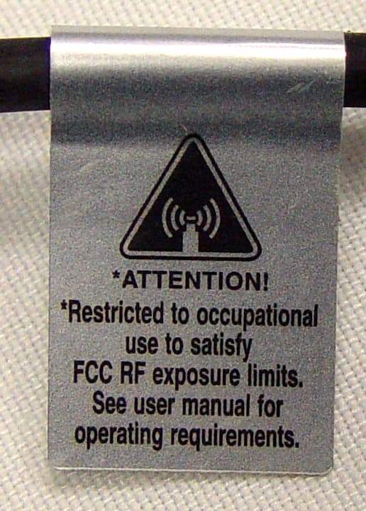
Click to zoom
Application Details
- Equipment Class
- TNB - Licensed Non-Broadcast Station Transmitter
- Date of Grant
- May 24, 2007
- Application Purpose
- Original Equipment
- Date of Application
- Mar 20, 2007
- Equipment Note
- MOTOTRBO VHF 45 Mobile Radio
- Frequency Range
- 136.00000000 - 174.00000000
- Company
- Motorola Solutions, Inc.
- Country
- United States
Documents & Files
Document Text
Text extracted from the exhibit documents filed with the FCC. Open a document above to read the original.
Users Manual
EXHIBIT 13A SHEET 1 OF 1 FCC ID: ABZ99FT3082 Date: March 19, 2007 Authorization & Evaluation Division Federal Communications Commission Laboratory 7435 Oakland Mills Road Columbia, MD 21046 Subject: Application for Certification of Transmitter with FCC ID: ABZ99FT3082; VHF Mobile (136 – 174 MHz), 25 – 54 Watts Variable Power Dear Sir or Madam: Motorola Inc., 1313 East Algonquin Road, Schaumburg, Illinois, herein submits application for Certification of equipment identified by FCC ID number ABZ99FT3082. This transmitter is primarily intended for use in a mobile radio application with capabilities for conventional and 2 to 1 TDMA digital communications with a conducted transmit power which is adjustable from 25 Watts to 45 Watts nominal, 54 Watts Maximum. Please note that this radio will also be sold to NTIA customers. There are two models using the same transmitter – one with a GPS receiver and one without. The subject transmitter complies with CFR Title 47, Section 90.203, in that the operator cannot directly program the transmit frequencies using only the normally accessible extern controls of the unit. Enclosed is a complete Certification Application. Please contact me if you require any additional information. Sincerely, /s/Donna Tokarz(signed) Donna Tokarz NPR Coordinator Tel: (847) 576-7245 Fax: (847) 538-4312 E-mail: [email protected] Deleted: Deleted: MOTOTRBO Deleted: Range Deleted: 50(150.0 Deleted: 6176 Deleted: 0 Deleted: ¶ Deleted: a GPS areceiver Deleted: The transmitter is exactly the same between the two types. On the non- GPS model, the GPS receiver circuitry is removed.¶ Deleted: from 136.0 to 174.0MHz
Users Manual
Contents English iii ContentsThis User Guide contains all the informatio n you need to use the MOTOTRBO XPR Series Mobiles.Important Safety Info rmation . . . . . . . . . . . . . . . . . vii Product Safety and RF Exposure Compliance . . vii Computer Software Copyrights . . . . . . . . . . . . . . viiiGetting Started . . . . . . . . . . . . . . . . . . . . . . . . . . . . . . 1 How to Use This User Guide . . . . . . . . . . . . . . . . . . 1What Your Dealer/Sys tem Administrator Can Tell You . . . . . . . . . . . . . . . . . . . . . . . . . . . . . . . 1Powering Up the Radio . . . . . . . . . . . . . . . . . . . . . . . 2Adjusting the Volume . . . . . . . . . . . . . . . . . . . . . . . . 2 Identifying Radio Controls . . . . . . . . . . . . . . . . . . . . 3 Radio Controls You Will Be Using . . . . . . . . . . . . . . 3Programmable Buttons . . . . . . . . . . . . . . . . . . . . . . . 4 Assignable Radio Functions . . . . . . . . . . . . . . . . . 4Assignable Settings/Utility Functions . . . . . . . . . . . 5 Accessing the Preprogr ammed Functions . . . . . . . . 5 Push-To-Talk (PTT) Button . . . . . . . . . . . . . . . . . . . . 6Switching Between Analog and Digital Mode . . . . . . 6 Identifying Status Indicators . . . . . . . . . . . . . . . . . . . 7 Display Icons . . . . . . . . . . . . . . . . . . . . . . . . . . . . . . . 7Call Icons . . . . . . . . . . . . . . . . . . . . . . . . . . . . . . . . . 8LED Indicators . . . . . . . . . . . . . . . . . . . . . . . . . . . . . 8Audio Tones . . . . . . . . . . . . . . . . . . . . . . . . . . . . . . . 9 Receiving and Making Calls . . . . . . . . . . . . . . . . . . . 9 Selecting a Zone . . . . . . . . . . . . . . . . . . . . . . . . . . . . 9Selecting a Radio Channel, Subscriber Alias or ID, or Group Alias or ID . . . . . . . . . . . . . . . . . . . 10Receiving and Resp onding to a Voice Call . . . . . . . 10 Receiving and Responding to a Group Call . . . . . 10Receiving and Respon ding to a Private Call . . . . . . . . . . . . . . . . . . . . . . . . . . . . . . . . . . . 11Receiving an All Call . . . . . . . . . . . . . . . . . . . . . . 12 Making a Voice Call . . . . . . . . . . . . . . . . . . . . . . . . 12 Making a Voice Call with the Channel Rocker . . . . . . . . . . . . . . . . . . . . . . . . . . . . . . . . . 12 Making a Group Call . . . . . . . . . . . . . . . . . . . . . 12Making a Private Call . . . . . . . . . . . . . . . . . . . . 13Making an All Call . . . . . . . . . . . . . . . . . . . . . . . 13 Making a Group or Private Call with the One Touch Call Button . . . . . . . . . . . . . . . . . . . . 14 Talkaround . . . . . . . . . . . . . . . . . . . . . . . . . . . . . . . 14Permanent Monitor . . . . . . . . . . . . . . . . . . . . . . . . . 15 Contents English iv Advanced Features . . . . . . . . . . . . . . . . . . . . . . . . . 15 Radio Check . . . . . . . . . . . . . . . . . . . . . . . . . . . . . 15 Sending a Radio Check . . . . . . . . . . . . . . . . . . . 16 Remote Monitor . . . . . . . . . . . . . . . . . . . . . . . . . . . 17 Initiating Remote Monitor . . . . . . . . . . . . . . . . . . 17 Scan Lists . . . . . . . . . . . . . . . . . . . . . . . . . . . . . . . . 18 Viewing an Entry in the Scan List . . . . . . . . . . . . 18Editing the Scan List . . . . . . . . . . . . . . . . . . . . . . 19 Adding a New Entry to the Scan List . . . . . . . . 19Deleting an Entry from the Scan List . . . . . . . . 19Setting and Editing Priority for an Entry in the Scan List . . . . . . . . . . . . . . . . . . . . . . . . 20 Scan . . . . . . . . . . . . . . . . . . . . . . . . . . . . . . . . . . . . 20 Starting and Stopping Scan . . . . . . . . . . . . . . . . 21Responding to a Transmission Dur ing a Scan . . 21 Deleting a Nuisance Channel . . . . . . . . . . . . . . . 22Restoring a Nuisance Channel . . . . . . . . . . . . . . 22 Contacts Settings . . . . . . . . . . . . . . . . . . . . . . . . . 23 Making a Group Call from Contacts . . . . . . . . . . 23Making a Private Call from Contacts . . . . . . . . . 23 Call Indicator Settings . . . . . . . . . . . . . . . . . . . . . . 24 Activating and Deactiva ting Call Ringers for Private Calls . . . . . . . . . . . . . . . . . . . . . . . . . 24 Activating and Deactivating Call Ringers for Text Messaging . . . . . . . . . . . . . . . . . . . . . . 25Assigning Ring Styles . . . . . . . . . . . . . . . . . . . . 25Escalating Alarm Tone Volume . . . . . . . . . . . . . . 26 Call Log Features . . . . . . . . . . . . . . . . . . . . . . . . . 26 Viewing Recent Calls . . . . . . . . . . . . . . . . . . . . . 26Missed Call Screen . . . . . . . . . . . . . . . . . . . . . . . 27Deleting a Call from a Call List . . . . . . . . . . . . . . 27 Call Alert Operation . . . . . . . . . . . . . . . . . . . . . . . . 28 Receiving and Acknowledging a Call Alert . . . . . 28Making a Call Alert from the Contacts List . . . . . . . . . . . . . . . . . . . . . . . . . . . . . . . . . . . 28Making a Call Alert with the One Touch Call Button . . . . . . . . . . . . . . . . . . . . . . . . . . . . . 29 Emergency Operation . . . . . . . . . . . . . . . . . . . . . . 29 Receiving an Emergency Alarm . . . . . . . . . . . . . 30Responding to an Emergency Alarm . . . . . . . . . 30Sending an Emergency Alarm . . . . . . . . . . . . . . 31Sending an Emergency Alarm with Call . . . . . . . 31 Sending an Emerge ncy Alarm with Voice to Follow . . . . . . . . . . . . . . . . . . . . . . . . . . . . . . . 32Reinitiating an Emergency Mode . . . . . . . . . . . . 32Exiting Emergency Mode . . . . . . . . . . . . . . . . . . 33 Contents English v Text Messaging Features . . . . . . . . . . . . . . . . . . . 33 Sending a Quick Text Message . . . . . . . . . . . . . . 33Sending a Quick Text Message with the One Touch Call Button . . . . . . . . . . . . . . . . . . . . 34Receiving a Text Message . . . . . . . . . . . . . . . . . 34Reading a Text Message . . . . . . . . . . . . . . . . . . . 34Managing Text Messages . . . . . …
Text truncated - open the document above for the full version.
Users Manual
English Product Safety and RF Energy Exposure Booklet for Mobile Two-Way Radios Installed in Vehicles or as Fixed Site Control Stations ATTENTION! The information provided in this document supersedes the general safety information contained in user guides published prior to February 2002. BEFORE USING THIS RADIO, READ THIS BOOKLET WHICH CONTAINS IMPORTANT OPERATING INSTRUCTIONS FOR SAFE USAGE AND RF ENERGY AWARENESS AND CONTROL INFORMATION FOR COMPLIANCE WITH RF ENERGY EXPOSURE LIMITS IN APPLICABLE NATIONAL AND INTERNATIONAL STANDARDS. © Motorola, Inc. 2005 8000 W. Sunrise Blvd., Ft. Lauderdale, FL 33322 *6881095C99* 68P81095C99-E 95C99-E_SafetyBooklet-Mobile_Eng.fm Page 1 Thursday, August 11, 2005 11:51 AM 2 English RF Energy Exposure Awareness and Control Information, and Operational Instructions for FCC Occupational Use Requirements NOTICE: This radio is intended for use in occupational/controlled conditions, where users have full knowledge of their exposure and can exercise control over their exposure to meet FCC limits. This radio device is NOT authorized for general population, consumer, or any other use. This 2-way radio uses electromagnetic energy in the radio frequency (RF) spectrum to provide communications between two or more users over a distance. It uses radio frequency (RF) energy or radio waves to send and receive calls. RF energy is one form of electromagnetic energy. Other forms include, but are not limited to, sunlight and x-rays. RF energy, however, should not be confused with these other forms of electromagnetic energy, which when used improperly, can cause biological damage. Very high levels of x-rays, for example, can damage tissues and genetic material. Experts in science, engineering, medicine, health, and industry work with organizations to develop standards for safe exposure to RF energy. These standards provide recommended levels of RF exposure for both workers and the general public. These recommended RF exposure levels include substantial margins of protection. All Motorola 2-way radios are designed, manufactured, and tested to ensure they meet government-established RF exposure levels. In addition, manufacturers also recommend specific operating instructions to users of 2-way radios. These instructions are important because they inform users about RF energy exposure and provide simple procedures on how to control it. 95C99-E_SafetyBooklet-Mobile_Eng.fm Page 2 Thursday, August 11, 2005 11:51 AM 3 English Please refer to the following Web sites for more information on what RF energy exposure is and how to control your exposure to assure compliance with established RF exposure limits. http://www.fcc.gov/oet/rfsafety/rf-faqs.html http://www.osha.gov/SLTC/radiofrequencyradiation/index.html Federal Communication Commission Regulations The FCC rules require manufacturers to comply with the FCC RF energy exposure limits for mobile 2-way radios before they can be marketed in the U.S. When 2-way radios are used as a consequence of employment, the FCC requires users to be fully aware of and able to control their exposure to meet occupational requirements. Exposure awareness can be facilitated by the use of a label directing users to specific user awareness information. Your Motorola 2-way radio has a RF exposure product label. Also, your Motorola user manual, or separate safety booklet, includes information and operating instructions required to control your RF exposure and to satisfy compliance requirements. Compliance with RF Exposure Standard Your Motorola two-way radio is designed and tested to comply with a number of national and international standards and guidelines (listed below) regarding human exposure to radio frequency electromagnetic energy. This radio complies with the IEEE and ICNIRP exposure limits for occupational/controlled RF exposure environment at duty factors of up to 50% talk-50% listen and is authorized by the FCC for occupational use. In terms of measuring RF energy for compliance with the FCC exposure guidelines, your radio antenna radiates measurable RF energy only while it is transmitting (during talking), not when it is receiving (listening) or in standby mode. 95C99-E_SafetyBooklet-Mobile_Eng.fm Page 3 Thursday, August 11, 2005 11:51 AM 4 English Your Motorola two-way radio complies with the following RF energy exposure standards and guidelines: ï United States Federal Communications Commission, Code of Federal Regulations; 47CFR part 2 sub-part J ï American National Standards Institute (ANSI) / Institute of Electrical and Electronic Engineers (IEEE) C95. 1-1992 ï Institute of Electrical and Electronic Engineers (IEEE) C95.1-1999 Edition ï International Commission on Non-Ionizing Radiation Protection (ICNIRP) 1998 ï Ministry of Health (Canada) Safety Code 6. Limits of Human Exposure to Radiofrequency Electromagnetic Fields in the Frequency Range from 3 kHz to 300 GHz, 1999 ï Australian Communications Authority Radiocommunications (Electromagnetic Radiation - Human Exposure) Standard, 2003 ï ANATEL, Brasil Regulatory Authority, Resolution 256 (April 11, 2001) ìadditional requirements for SMR, cellular, and PCS product certification.î RF Exposure Compliance and Control Guidelines and Operating Instructions To control exposure to yourself and others and to ensure compliance with the RF exposure limits, always adhere to the following procedures. Guidelines: ï User awareness instructions should accompany device when transferred to other users. ï Do not use this device if the operational requirements described herein are not met. Instructions: ïTransmit no more than the rated duty factor of 50% of the time. To t r a n s m i t (talk), push the Push-To-Talk (PTT) button or, for radios equipped with VOX, speak into the microphone. The red LED will illuminate when the radio is 95C99-E_SafetyBooklet-Mobile_Eng.fm Page 4 Thursday, August 11, 2005 11:51 AM 5 English transmitting. To receive calls, release the PTT button, or, for radios equipped with VO…
Text truncated - open the document above for the full version.
Attestation Statements
MOTOROLA INC FCC ID: ABZ99FT3082 CERTIFICATION OF DATA Pursuant to 47 CFR 2.1517 (g) The technical data supplied with this application, having been taken under my supervision, is hereby duly certified. The following is a statement of my qualifications: 1) I have received a BSEE and a MSEE degree in Electrical Engineering from the University of Illinois at Chicago, Chicago, Illinois. 2) I have 7 years experience in developing, testing, and certifying Land Mobile Communications Products. NAME: Susan O. Brauer SIGNATURE: /s/ Susan O. Brauer (signed) Susan O. Brauer DATE: February 28, 2007 POSITION: Engineering Section Manager I hereby certify that the above application was prepared under my direction and that to the best of my knowledge and belief, the facts set forth in the application and accompanying technical data are true and correct. NAME: Larry D. Larsen SIGNATURE: /s/ Larry D. Larsen (signed) Larry D. Larsen DATE: February 28, 2007 POSITION: Engineering Section Manager EXHIBIT 2 SHEET 1 OF 1
Cover Letter(s)
FCC ID: ABZ99FT3082 Date: March 19, 2007 Authorization & Evaluation Division Federal Communications Commission Laboratory 7435 Oakland Mills Road Columbia, MD 21046 Subject: Application for Certification of Transmitter with FCC ID: ABZ99FT3082; VHF Mobile (136 – 174 MHz), 25 – 54 Watts Variable Power Dear Sir or Madam: Motorola Inc., 1313 East Algonquin Road, Schaumburg, Illinois, herein submits application for Certification of equipment identified by FCC ID number ABZ99FT3082. This transmitter is primarily intended for use in a mobile radio application with capabilities for conventional and 2 to 1 TDMA digital communications with a conducted transmit power which is adjustable from 25 Watts to 45 Watts nominal, 54 Watts Maximum. Please note that this radio will also be sold to NTIA customers. There are two models using the same transmitter – one with a GPS receiver and one without. The subject transmitter complies with CFR Title 47, Section 90.203, in that the operator cannot directly program the transmit frequencies using only the normally accessible extern controls of the unit. Enclosed is a complete Certification Application. Please contact me if you require any additional information. Sincerely, /s/Donna Tokarz(signed) Donna Tokarz NPR Coordinator Tel: (847) 576-7245 Fax: (847) 538-4312 E-mail: [email protected] EXHIBIT 13A SHEET 1 OF 1
Cover Letter(s)
FCC ID: ABZ99FT3082 Date: March 19, 2007 Authorization & Evaluation Division Federal Communications Commission Laboratory 7435 Oakland Mills Road Columbia, MD 21046 Subject: Confidentiality Request for Transmitter with FCC ID: ABZ99FT3082; VHF Mobile (136 – 174 MHz) Dear Sir or Madam: Motorola is requesting that Exhibit 4 (Circuit Descriptions), Exhibit 5 (Schematic Diagrams), Exhibit 10 (Parts List and Tune Up Procedures), and Exhibit 12 (Operational Description) not be made routinely available for public inspection. Motorola considers the information in these exhibits to be classified as trade secrets, pursuant to 47 CFR Section 0.457(d) and Section 552(b)(4) of the Freedom of Information Act. We are also requesting that the FCC mark Exhibit 3 (External Photos) and Exhibit 9, (Internal Photos) as Temporary or Short-Term Confidentiality as outlined in Public Notice DA 04-1705, dated June 15, 2004. This provision will give Motorola temporary confidentiality prior to product launch. Please mark Exhibits 4, 5, 10, and 12 as “Confidential” and Exhibit 3 (External Photos) & 9 (Internal Photos) as “Temporary Confidential”. Please contact me if you require any additional information. Sincerely, /s/Donna Tokarz(signed) Donna Tokarz NPR Coordinator Tel: (847) 576-7245 Fax: (847) 538-4312 E-mail: [email protected] EXHIBIT 13A SHEET 1 OF 1
Cover Letter(s)
FCC ID: ABZ99FT3082 11 th May 2007 Mr. Stanley Lyles Equipment Authorization Branch Federal Communications Commission Laboratory 7435 Oakland Mills Road Columbia, MD 21046 Re: Form 731 Confirmation Number: EA261741 with FCC ID: ABZ99FT3082 and Correspondence Number: 33018. Dear Mr. Lyles; Motorola Inc., 8000 West Sunrise Boulevard, Fort Lauderdale, Florida 33322, herein submits its response to the 8 th May 2007 request for information in Correspondence Number 33018. Q1) Photos show RF exposure notice label only on microphone cord - unclear whether and how microphone assembly with label will always be used with radio (eg use with un- labeled microphones precluded), or whether other or additional label schemes may be appropriate - if not in filing already, please explain and/or revise A1) All microphones available for this product have the label attached. No other acceptable location or scheme of marking for this label is available for this product. Q2) For part 90 devices, output power listed on a grant should represent the manufacturer's rated output power, i.e. 45 W for this application. RF exposure evaluations for Part 90 devices (when applicable) must be done using the actual maximum output power achievable for production units, up to 20-percent above rated power, or if maximum output is not used then filing must demonstrate that the device will not operate at levels up to 20-percent above rated power. When RF exposure is done at higher than manufacturer's rated output power, the grant line-item shall list the rated output power, but maximum power as allowed by 90.205(r) variation, which may also be what is reported in the filing as measured, may be listed in the grant remarks field. For this application, FCC will revise Form 731 line-entries in accordance with above. A2) We concur and accept the revised Form 731. Q3) If not in filing already, please explain effects on measured MPE data and steps FCC ID: ABZ99FT3082 taken to ensure results for 2:1 TDMA signal are correct, probe calibration is valid, etc. A3) MPE reported data was measured with DUT in its maximum 100% (CW) duty cycle with an approximate output power of 54W. TDMA 2:1, as explained in the report, defines the signal as transmitting one slot (30ms) within a two slot (60ms) frame or 50% of the time. The average power over the frame is equivalent to 27W not 54W and therefore data for TDMA 2:1 is not present. Q4) If not in filing already, please explain effects on calculated field and SAR data and steps taken to ensure results for 2:1 TDMA signal are correct, FDTD input signal represents actual exposure, etc. A4) SAR simulations were conducted with a CW (100% duty cycle) signal. TDMA 2:1, as explained in the report, defines the signal as transmitting on one slot (30ms) within a two slot (60ms) frame or 50% of the time. The average power over the frame is equivalent to half of a CW signal and therefore data for TDMA 2:1 is not present. Q5) The filing must have a justification letter for extended frequencies outside of applied rule part. Operation must be justified under 2.807. For example, Government / Military use or exportation to other countries has been allowed. A5) This product will be marketed to various elements of the US Government and will also be exported to Canada whose certification will be under IC:109-99FT3082. Q6) Justification letter from grantee must indicate marketing plans to ensure USA users, other than those specifically identified, cannot operate device outside bands allowed under the relevant rule parts applied for. A6) The software used by the Dealer personnel will recognize the frequency limits of the Grant and limit frequency selections to these limits. The Dealer personnel are responsible to only select frequencies that are granted to the station. • This radio complies with Section 90.203 of the Rules in that the operator cannot directly program transmit frequencies using the unit's normally accessible external controls • Also, these radios are marketed through Authorized Dealers who programs frequencies authorized by the FCC on to the radios per the listing on the customer’s FCC License. Please contact me if you require any additional information. Sincerely, /s/ Larry D. Larsen (signed) Eng. Section Manager Email: [email protected]
Cover Letter(s)
FCC ID: ABZ99FT3082 17 th May 2007 Mr. Stanley Lyles Equipment Authorization Branch Federal Communications Commission Laboratory 7435 Oakland Mills Road Columbia, MD 21046 Re: Form 731 Confirmation Number: EA261741 with FCC ID: ABZ99FT3082 and Correspondence Number: 33097. Dear Mr. Lyles; Motorola Inc., 1313 E. Algonquin Rd, Schaumburg, IL, herein submits its response to the 17 th May 2007 request for information in Correspondence Number 33097. Q1) Your requests confidentiality letter shows Block Diagrams, Schematic, Parts List/Tune Up Info and Operational Description. Your Exhibits shows Exhibit 5 Schematics, Exhibit 10 Parts List/Tune Up Info and Exhibit 12 Operational Description is request confidentiality. Please clarify. Please submit a new replacement confidentiality letter. A1) We have reviewed our confidentiality letter, the contents of the exhibits and the OET Exhibits Summary List. Listed below is the summary of the confidentiality request as submitted to the OET electronic filing system. Exhibit Type Description Permanent Short-Term Confidential Confidential External Photos Exhibit 3 Extrn photos No Yes Internal Photos Exhibit 9 Internal Photos No Yes Parts List/Tune Up Info Exhibit 10 Part List Yes No Operational Description Exhibit 12 Operational Description Yes No Operational Description Exhibit 4 Circuit Description Yes No Schematics Exhibit 5 Schematics Yes No In addition an erroneous document was previously filed as exhibit 8b. The correct document has been submitted to the OET electronic filing system. Please ignore and if possible delete the previous exhibit 8b. Please contact me if you require any additional information. Sincerely, /s/ Larry D. Larsen (signed) Eng. Section Manager Email: [email protected]
External Photos
MOTOROLA INC FCC ID: ABZ99FT3082 GENERAL VIEW, 256 CHANNEL MODEL WITH MICROPHONE (CLOSE-UP OF RF EXPOSURE LABEL ON FOLLOWING PAGE) EXHIBIT 3 SHEET 1 OF 5 MOTOROLA INC FCC ID: ABZ99FT3082 RF EXPOSURE LABEL (CLOSE-UP VIEW) EXHIBIT 3 SHEET 2 OF 5 MOTOROLA INC FCC ID: ABZ99FT3082 FRONT VIEW, 256 CHANNEL MODEL FRONT VIEW, 32 CHANNEL MODEL EXHIBIT 3 SHEET 3 OF 5 MOTOROLA INC FCC ID: ABZ99FT3082 BOTTOM VIEW, SHOWING FCC ID LABEL (CLOSE-UP OF FCC ID LABEL ON FOLLOWING PAGE) EXHIBIT 3 SHEET 4 OF 5 MOTOROLA INC FCC ID: ABZ99FT3082 CLOSE-UP VIEW OF FCC ID LABEL EXHIBIT 3 SHEET 5 OF 5
ID Label/Location Info
MOTOROLA INC FCC ID: ABZ99FT3082 LIST OF EXHIBITS DESCRIPTION EXHIBIT REFERENCE I. Identification Label Information 1 2.1033-(c) 11 & General Information 1A 1. Production Plans 2.1033-(c) 2. Application References 2.1061 3. Data Submittal Procedure II. Certification of Data 2 2.1517-(g) III. External Photographs 3 2.1033-(c) 12 IV. Circuit Descriptions 4 V. Schematic Diagrams 5 2.1033-(c) 10 VI. Test Report 1. Data Index 6 2. RF Output Data 6A 2.1046 3. Modulation Characteristics A. Audio Response & Low Pass Filter Response 6B, 6C 2.1047-(a) B. Modulation Limiting 6D 2.1047-(b) 4. Occupied Bandwidth 6E 2.1049 5. Conducted Spurious Emissions 6F 2.1051 6. Radiated Spurious Emissions 6G 2.1053 7. Frequency Stability A. Frequency Stability vs. Temperature 6H-1 2.1055 B. Frequency Stability vs. Supply Voltage 6H-2 2.1055 8. Transient Frequency Behavior 6I 90.214 VII. Test Set-up Procedures 7 2.1041 VIII. Instruction Manuals 8 2.1033-(c) 3 IX. Internal Photographs 9 2.1033-(c) 11, 12 X. Parts List and Tune-up Procedures 10 2.1033-(c) 9, 10 XI. RF Exposure Information 11 2.1091 XII. Operational Description 12 2.1033-(c) 4, 5 1. Technical Characteristics 2. Application XIII. Cover Letter 13 EXHIBIT 1 SHEET 1 OF 2 MOTOROLA INC FCC ID: ABZ99FT3082 IDENTIFICATION LABEL Pursuant to 47 CFR 2.1033(c) LOCATION A nameplate of the type presented below will be affixed to every transmitter. It will be placed on the bottom of the unit near the front. Shown below is a photo of the actual label affixed to the cast chassis of the transmitter. Please note that Motorola complies to FCC Rule Part 2.925 (d) that the label is permanently affixed and is readily visible to the purchaser at the time of purchase TYPE The label is a paper polyester film laminated with a pressure sensitive adhesive backing. The adhesive is a permanent type acrylic with a minimum peel strength of 40 oz/inch. EXHIBIT 1 SHEET 2 OF 2 MOTOROLA INC FCC ID: ABZ99FT3082 EXHIBIT 1A – GENERAL INFORMATION 1. Production Plans – Pursuant 2.1033 (c) Quantity production is planned. 2. Application References: TIA/EIA-603 Land Mobile FM or PM Communications Equipment Measurement and Performance Standards Code of Federal Regulations Title 47, Part 2, Sec. 2.1033-2.1057, and Part 90 Sec. 90.210. 3. Data Submittal Procedure: Data is supplied in accordance with Part 2, Sub-part J of the Commissions’ rules. The intended use of this transceiver includes applications covered in the Code of Federal Regulations Title 47, Part 90. Maximum transmitter power shall not be adjustable by the user. EXHIBIT 1A SHEET 1 OF 1
Internal Photos
MOTOROLA INC FCC ID: ABZ99FT3082 TOP VIEW OF GPS MODEL WITH CHASSIS TOP COVER REMOVED (MATING SURFACES OF TOP COVER AND CIRCUIT BOARD IN CHASSIS ARE SHOWN) EXHIBIT 3 SHEET 1 OF 4 MOTOROLA INC FCC ID: ABZ99FT3082 TOP VIEW OF NON-GPS MODEL WITH CHASSIS TOP COVER REMOVED (MATING SURFACES OF TOP COVER AND CIRCUIT BOARD IN CHASSIS ARE SHOWN) EXHIBIT 3 SHEET 2 OF 4 MOTOROLA INC FCC ID: ABZ99FT3082 TOP VIEW OF GPS MODEL WITH CIRCUIT BOARD REMOVED FROM CHASSIS (MATING SURFACES OF CIRCUIT BOARD AND CHASSIS ARE SHOWN) EXHIBIT 3 SHEET 3 OF 4 MOTOROLA INC FCC ID: ABZ99FT3082 TOP VIEW OF NON-GPS MODEL WITH CIRCUIT BOARD REMOVED FROM CHASSIS (MATING SURFACES OF CIRCUIT BOARD AND CHASSIS ARE SHOWN) EXHIBIT 3 SHEET 4 OF 4
RF Exposure Info
FCC ID: ABZ99FT3082 RF EXPOSURE INFORMATION Pursuant 47 CFR 2.1091 In accordance with 47 CFR 2.1091(c) this transmitter has been subjected to routine environmental evaluation for RF exposure and found to be compliant with the limits specified in 47 CFR 2.1091(d) for mobile devices, using measurements per methods stated in 47 CFR 2.1091(d)(1). The complete S.A.R. EME Compliance Test Report is attached as Exhibit 11B. EXHIBIT 11A SHEET 1 OF 1
RF Exposure Info
FCC ID: ABZ99FT3082 SR4759 Form-MPE Vehicle rpt. Rev 3.00 Page 1 of 63 TESTING CERT: 2518.01 FCC ID: ABZ99FT3082 DECLARATION OF COMPLIANCE MPE ASSESSMENT Networks & Enterprise EME Test Laboratory 8000 West Sunrise Blvd Fort Lauderdale, FL. 33322 Date of Report: March 19, 2007 Report Revision: Rev. A Report ID: FCC MPE rpt_XPR VHF Rev A_070319_SR4759 Responsible Engineer: Stephen Whalen (EME Principle Staff Eng.) Date/s Tested: 2/8/2007-2/14/2007 & 2/20/2007-2/21/2007 Manufacturer/Location: Motorola / Penang Date submitted for test: 1/26/2007 DUT Description: VHF, 25-45W, w/ GPS and a mini-U connector. Test TX mode(s): CW Max. Power output: 54W, 50% Duty Cycle TX Frequency Bands: 136-174MHz Signaling type: FM and TDMA 2:1 Model(s) Tested: PMUD2043A Model(s) Certified: PMUD2043A Serial Number(s): 038THA0020 Classification: Occupational Controlled (Operator); General Population/Uncontrolled (Passengers/Bystanders) Rule Part(s): 2.1091 (d) Approved Accessories: Antenna(s): HAD4006A (136-144MHz ¼ wave roof mount antenna; 0dBd gain, Mini U Connector) HAD4007A (146-150.8MHz ¼ wave roof mount antenna; 0dBd gain, Mini U Connector) HAD4008A (150.8-162MHz ¼ wave roof mount antenna; 0dBd gain, Mini U Connector) HAD4009A (162-174MHz ¼ wave roof mount antenna; 0dBd gain, Mini U Connector) HAD4014A (146-172MHz 5/8 wave roof mount antenna; 3.0dBd gain, Mini U Connector) RAD4198A (136-144MHz ¼ wave roof mount antenna; 0dBd gain, BNC Connector) RAD4199A (146-150.8MHz ¼ wave roof mount antenna; 0dBd gain, BNC Connector) RAD4200A (150.8-162MHz ¼ wave roof mount antenna; 0dBd gain, BNC Connector) RAD4201A (162-174MHz ¼ wave roof mount antenna; 0dBd gain, BNC Connector) RAD4214A (136-144MHz ¼ wave roof mount GPS Combo antenna; 0dBd gain, Mini U Connector) RAD4215A (146-150.8MHz ¼ wave roof mount GPS Combo antenna; 0dBd gain, Mini U Connector) RAD4216A (150.8-162MHz ¼ wave roof mount GPS Combo antenna; 0dBd gain, Mini U Connector) RAD4217A (162-174MHz ¼ wave roof mount GPS Combo antenna; 0dBd gain, Mini U Connector) RAD4218A (146-172MHz 5/8 wave roof mount GPS Combo antenna; 3.0dBd gain, Mini U Connector) RAD4219A (136-144MHz ¼ wave roof mount GPS Combo antenna; 0dBd gain, BNC Connector) RAD4220A (146-150.8MH…
Text truncated - open the document above for the full version.
Contact Information
Applicant
Matthew Nawrocki
Technical Contact
Motorola, IncLarry D Larsen
[email protected]847 538-2239
1313 E. Algonquin Rd · Schaumburg, Illinois · United States
Non-Technical Contact
Motorola, IncDonna Tokarz
[email protected]847 576-7245
Technical Specifications
| # | Rule Parts | Frequency Range | Power Output | Emission | Tolerance |
|---|---|---|---|---|---|
| 5 | 9 | 136 MHz - 174 MHz | 45 W | 7K60FXE | 1.5 ppm |
Other Applications from Motorola Solutions, Inc.

ABZ89FT4940
Aug 06, 2026Non Broadcast Transmitter
Equipment Class
TNB - Licensed Non-Broadcast Station TransmitterABZ89FT4950
Jun 25, 2026Non-Broadcast Transmitter
Equipment Class
TNB - Licensed Non-Broadcast Station TransmitterABZ89FT5901
Jun 20, 2024Non Broadcast Transmitter
Equipment Class
TNB - Licensed Non-Broadcast Station Transmitter
ABZ99FT5101B
May 02, 2023Non Broadcast Transmitter
Equipment Class
PCB - PCS Licensed Transmitter
ABZ99FT3095B
Mar 26, 2023Non Broadcast Transmitter
Equipment Class
TNB - Licensed Non-Broadcast Station Transmitter