ABZ99FT3087Mobile Radio
Motorola Solutions, Inc.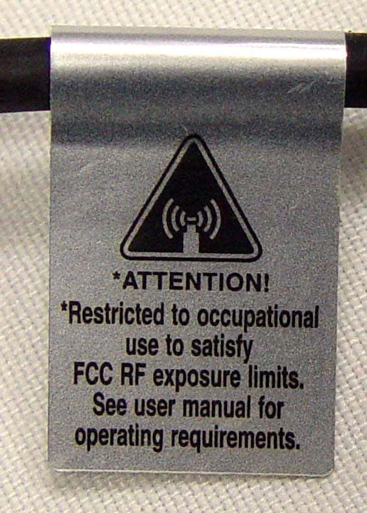
Click to zoom
Application Details
- Equipment Class
- DSS - Part 15 Spread Spectrum Transmitter
- Date of Grant
- Mar 08, 2012
- Application Purpose
- Original Equipment
- Date of Application
- Dec 06, 2011
- Equipment Note
- Mobile Radio
- Frequency Range
- 2400.00000000 - 2483.50000000
- Company
- Motorola Solutions, Inc.
- Country
- United States
Documents & Files
Document Text
Text extracted from the exhibit documents filed with the FCC. Open a document above to read the original.
Users Manual
M MOTOTRBO XPR TM 5550 Color Display Mobile User Guide 68009504001-A Declaration of Conformity English i Declaration of Conformity This declaration is applicable to your radio only if your radio is labeled with the FCC logo shown below. DECLARATION OF CONFORMITYPer FCC CFR 47 Part 2 Section 2.1077(a)Responsible Party Name: Motorola Solutions, Inc.Address: 1303 East Algonquin Road, Schaumburg, IL 60196-1078, U.S.A.Phone Number: 1-800-927-2744Hereby declares that the product: Model Name: XPR 5550 conforms to the following regulations: FCC Part 15, subpart B, section 15.107(a), 15.107(d) and section 15.109(a) Class B Digital DeviceAs a personal computer peripheral, this device complies with Part 15 of the FC C Rules. Operation is subject to the following two conditions: 1. This device may not cause harmful interference, and 2. This device must accept any interference received, including interference that may cause undesired operation. Declaration of Conformity English ii Note: This equipment has been tested and found to comply with the li mits for a Class B digital device, pursuant to part 15 of the FCC Rules. These limits are designed to provi de reasonable protection against harmful interference in a residential installation. This equipment generates, us es and can radiate radio frequency energy and, if not installed and used in accordance with the instructions, may cause harmful interference to radio communications. However, there is no guarantee that interference wi ll not occur in a particular installation. If this equipment does cause harmful interference to radi o or television reception, which can be determined by turning the equipment off and on, the user is encouraged to try to correct the interference by one or more of the following measures: • Reorient or relocate the receiving antenna. • Increase the separation between the equipment and receiver. • Connect the equipment into an outlet on a circuit differ ent from that to which the receiver is connected. • Consult the dealer or an experienc ed radio/TV technician for help. Contents English iii ContentsThis User Guide contains all the information you need to use the MOTOTRBO XPR Series Digital Mobile Radios.Declaration of Conformity . . . . . . . . . . . . . . . . . . . . . iImportant Safety Information . . . . . . . . . . . . . . . . . ix Product Safety and RF Exposure Compliance . . .ix Software Version . . . . . . . . . . . . . . . . . . . . . . . . . . . ixComputer Software Copyrights . . . . . . . . . . . . . . . . x Getting Started . . . . . . . . . . . . . . . . . . . . . . . . . . . . . . 1 How to Use This User Guide . . . . . . . . . . . . . . . . . . 1What Your Dealer/System Administrator Can Tell You . . . . . . . . . . . . . . . . . . . . . . . . . . . . . . . 1Powering Up the Radio . . . . . . . . . . . . . . . . . . . . . . . 2Adjusting the Volume . . . . . . . . . . . . . . . . . . . . . . . . 2 Identifying Radio Controls . . . . . . . . . . . . . . . . . . . . 3 Radio Controls . . . . . . . . . . . . . . . . . . . . . . . . . . . . . 3Programmable Buttons . . . . . . . . . . . . . . . . . . . . . . . 4 Assignable Radio Functions . . . . . . . . . . . . . . . . . 4Assignable Settings or Utility Functions . . . . . . . . . 6 Accessing the Programmed Functions . . . . . . . . . . . 6Push-To-Talk (PTT) Button . . . . . . . . . . . . . . . . . . . . 7 Using the Volume/Channel Knob . . . . . . . . . . . . . . . 7Switching Between Conventional Analog and Digital Mode . . . . . . . . . . . . . . . . . . . . . . . . . . . . . . . . . . . . . 8Capacity Plus . . . . . . . . . . . . . . . . . . . . . . . . . . . . . . 8 Identifying Status Indicators . . . . . . . . . . . . . . . . . . . 9 Display Icons . . . . . . . . . . . . . . . . . . . . . . . . . . . . . . . 9Call Icons . . . . . . . . . . . . . . . . . . . . . . . . . . . . . . . . 11Advanced Menu Icons . . . . . . . . . . . . . . . . . . . . . . 11Mini Notice Icons . . . . . . . . . . . . . . . . . . . . . . . . . . . 12Sent Item Icons . . . . . . . . . . . . . . . . . . . . . . . . . . . 12Bluetooth Device Icons . . . . . . . . . . . . . . . . . . . . . . 13LED Indicators . . . . . . . . . . . . . . . . . . . . . . . . . . . . 13Indicator Tones . . . . . . . . . . . . . . . . . . . . . . . . . . . . 14Audio Tones . . . . . . . . . . . . . . . . . . . . . . . . . . . . . . 15 Receiving and Making Calls . . . . . . . . . . . . . . . . . . 15 Selecting a Site . . . . . . . . . . . . . . . . . . . . . . . . . . . 15Selecting a Zone . . . . . . . . . . . . . . . . . . . . . . . . . . . 16Selecting a Radio Channel, Su bscriber Alias or ID, or Group Alias or ID . . . . . . . . . . . . . . . . . . . . . . . . . . 16Receiving and Responding to a Radio Call . . . . . . 17 Receiving and Responding to a Group Call . . . . . 17Receiving and Responding to a Private Call . . . 18 Receiving an All Call . . . . . . . . . . . . . . . . . . . . . . 19Receiving and Responding to a Selective Call . . 19 Making a Radio Call . . . . . . . . . . . . . . . . . . . . . . . . 20 Contents English iv Making a Call with the Volume/Channel Knob . . 21 Making a Group Call . . . . . . . . . . . . . . . . . . . . 21Making a Private Call . . . . . . . . . . . . . . . . . . . 22Making an All Call . . . . . . . . . . . . . . . . . . . . . . 22Making a Selective Call . . . . . . . . . . . . . . . . . . 23 Making a Call with the Scroll Up and Scroll Down Buttons . . . . . . . . . . . . . . . . . . . . . . . . . . . . . . . . 24Making a Call with the Cha nnel Up and Channel Down Buttons . . . . . . . . . . . . . . . . . . . . . . . . . . . . . . . . 24Making a Group or Private Call with the One Touch Access Button . . . . . . . . . . . . . . . . . . . . . . . . . . 24 Stopping a Radio Call . . . . . . . . . . . . . . . . . . . . . . 25Talkaround . . . . . . . . . . . . . . . . . . . . . . . . . . . . . . . 26Permanent Monitor . . . . . . . . . . . . . . . . . . . . . . . . . 26 Advanced Features . . . . . .…
Text truncated - open the document above for the full version.
Users Manual
English Product Safety and RF Energy Exposure Booklet for Mobile Two-Way Radios Installed in Vehicles or as Fixed Site Control Stations ATTENTION! The information provided in this document supersedes the general safety information contained in user guides published prior to January 2008. BEFORE USING THIS RADIO, READ THIS BOOKLET WHICH CONTAINS IMPORTANT OPERATING INSTRUCTIONS FOR SAFE USAGE AND RF ENERGY AWARENESS AND CONTROL INFORMATION FOR COMPLIANCE WITH RF ENERGY EXPOSURE LIMITS IN APPLICABLE NATIONAL AND INTERNATIONAL STANDARDS. © 2005 – 2009 by Motorola, Inc. All rights reserved. 12/09 1301 E. Algonquin Rd., Schaumburg, IL 60196-1078, U.S.A. *6881095C99* 6881095C99-G *NNTN7851B* NNTN7851C 6881095C99-G.book Page 1 Monday, December 21, 2009 3:33 PM 2 English RF Energy Exposure Awareness and Control Information, and Operational Instructions for FCC Occupational Use Requirements NOTICE: This radio is intended for use in occupational/controlled conditions, where users have full knowledge of their exposure and can exercise control over their exposure to meet FCC limits. This radio device is NOT authorized for general population, consumer, or any other use. This two-way radio uses electromagnetic energy in the radio frequency (RF) spectrum to provide communications between two or more users over a distance. It uses radio frequency (RF) energy or radio waves to send and receive calls. RF energy is one form of electromagnetic energy. Other forms include, but are not limited to, sunlight and x-rays. RF energy, however, should not be confused with these other forms of electromagnetic energy, which when used improperly, can cause biological damage. Very high levels of x-rays, for example, can damage tissues and genetic material. Experts in science, engineering, medicine, health, and industry work with organizations to develop standards for safe exposure to RF energy. These standards provide recommended levels of RF exposure for both workers and the general public. These recommended RF exposure levels include substantial margins of protection. All Motorola two-way radios are designed, manufactured, and tested to ensure they meet government-established RF exposure levels. In addition, manufacturers also recommend specific operating instructions to users of two-way radios. These instructions are important because they inform users about RF energy exposure and provide simple procedures on how to control it. 6881095C99-G.book Page 2 Monday, December 21, 2009 3:33 PM 3 English Please refer to the following Web sites for more information on what RF energy exposure is and how to control your exposure to assure compliance with established RF exposure limits. http://www.fcc.gov/oet/rfsafety/rf-faqs.html http://www.osha.gov/SLTC/radiofrequencyradiation/index.html Federal Communication Commission Regulations The FCC rules require manufacturers to comply with the FCC RF energy exposure limits for mobile two-way radios before they can be marketed in the U.S. When two-way radios are used as a consequence of employment, the FCC requires users to be fully aware of and able to control their exposure to meet occupational requirements. Exposure awareness can be facilitated by the use of a label directing users to specific user awareness information. Your Motorola two-way radio has a RF exposure product label. Also, your Motorola user manual, or separate safety booklet, includes information and operating instructions required to control your RF exposure and to satisfy compliance requirements. Compliance with RF Exposure Standard Your Motorola two-way radio is designed and tested to comply with a number of national and international standards and guidelines (listed below) regarding human exposure to radio frequency electromagnetic energy. This radio complies with the IEEE and ICNIRP exposure limits for occupational/controlled RF exposure environment at duty factors of up to 50% talk-50% listen and is authorized by the FCC for occupational use. In terms of measuring RF energy for compliance with the FCC exposure guidelines, your radio antenna radiates measurable RF energy only while it is transmitting (during talking), not when it is receiving (listening) or in standby mode. 6881095C99-G.book Page 3 Monday, December 21, 2009 3:33 PM 4 English Your Motorola two-way radio complies with the following RF energy exposure standards and guidelines: • United States Federal Communications Commission, Code of Federal Regulations; 47CFR part 2 sub-part J • American National Standards Institute (ANSI)/Institute of Electrical and Electronic Engineers (IEEE) C95. 1-1992 • Institute of Electrical and Electronic Engineers (IEEE) C95.1-1999 Edition • Institute of Electrical and Electronic Engineers (IEEE) C95.1-2005 Edition • International Commission on Non-Ionizing Radiation Protection (ICNIRP) 1998 • Ministry of Health (Canada) Safety Code 6. Limits of Human Exposure to Radiofrequency Electromagnetic Fields in the Frequency Range from 3 kHz to 300 GHz, 1999 • Australian Communications Authority Radiocommunications (Electromagnetic Radiation - Human Exposure) Standard, 2003 • ANATEL, Brasil Regulatory Authority, Resolution 256 (April 11, 2001) “additional requirements for SMR, cellular, and PCS product certification” RF Exposure Compliance and Control Guidelines and Operating Instructions To control exposure to yourself and others and to ensure compliance with the RF exposure limits, always adhere to the following procedures. Guidelines: • User awareness instructions should accompany device when transferred to other users. • DO NOT use this device if the operational requirements described herein are not met. 6881095C99-G.book Page 4 Monday, December 21, 2009 3:33 PM 5 English Instructions: •Transmit no more than the rated duty factor of 50% of the time. To transmit (talk), push the Push-To-Talk (PTT) button or, for radios equipped with VOX, speak into the microphone. The red LED will illuminate when the radio is transmitting. To r…
Text truncated - open the document above for the full version.
Attestation Statements
MOTOROLA INC FCC ID: ABZ99FT3087 EXHIBIT 2 SHEET 1 OF 1 CERTIFICATION OF DATA Pursuant to 47 CFR 2.1517 (g) The technical data supplied with this application, having been taken under my supervision, is hereby duly certified. The following is a statement of my qualifications: 1) I have received a BSEE degree from the University of Wisconsin-Platteville, Platteville, WI and a MSEE degree from Illinois Institute of Technology, Chicago, Illinois. 2) I have 14 years experience in developing, testing, and certifying Land Mobile Communications Products. NAME: Matthew R. Schneider SIGNATURE: /s/ Matthew R. Schneider(signed) Matthew R. Schneider DATE: November 11, 2011 POSITION: Engineering Section Manager I hereby certify that the above application was prepared under my direction and that to the best of my knowledge and belief, the facts set forth in the application and accompanying technical data are true and correct. NAME: Larry D. Larsen SIGNATURE: /s/ Larry D. Larsen (signed) Larry D. Larsen DATE: POSITION: Regulatory Coordinator
External Photos
MOTOROLA SOLUTIONS, INC FCC ID: ABZ99FT3087 EXHIBIT 3 SHEET 1 OF 5 GENERAL VIEW, 1000 CHANNEL MODEL WITH MICROPHONE (CLOSE-UP OF RF EXPOSURE LABEL ON FOLLOWING PAGE) MOTOROLA SOLUTIONS, INC FCC ID: ABZ99FT3087 EXHIBIT 3 SHEET 2 OF 5 RF EXPOSURE LABEL (CLOSE-UP VIEW) MOTOROLA SOLUTIONS, INC FCC ID: ABZ99FT3087 EXHIBIT 3 SHEET 3 OF 5 FRONT VIEW, 1000 CHANNEL MODEL FRONT VIEW, 32 CHANNEL MODEL MOTOROLA SOLUTIONS, INC FCC ID: ABZ99FT3087 EXHIBIT 3 SHEET 4 OF 5 BOTTOM VIEW, SHOWING FCC ID LABEL (CLOSE-UP OF FCC ID LABEL ON FOLLOWING PAGE) MOTOROLA SOLUTIONS, INC FCC ID: ABZ99FT3087 EXHIBIT 3 SHEET 5 OF 5 CLOSE-UP VIEW OF FCC ID LABEL
ID Label/Location Info
MOTOROLA SOLUTIONS, INC FCC ID: ABZ99FT3087 EXHIBIT 1 SHEET 1 OF 2 IDENTIFICATION LABEL Pursuant to 47 CFR 2.1033(c) LOCATION A nameplate of the type presented below will be affixed to every transmitter. It will be placed on the bottom of the unit near the front. Shown below is a photo of the actual label affixed to the cast chassis of the transmitter. TYPE The label is a paper polyester film laminated with a pressure sensitive adhesive backing. The adhesive is a permanent type acrylic with a minimum peel strength of 40 oz/inch. MOTOROLA SOLUTIONS, INC FCC ID: ABZ99FT3087 EXHIBIT 1A SHEET 1 OF 1 EXHIBIT 1A – GENERAL INFORMATION 1. Production Plans – Pursuant 2.1033 (c) Quantity production is planned. 2. Application References: TIA/EIA-603 Land Mobile FM or PM Communications Equipment Measurement and Performance Standards Code of Federal Regulations Title 47, Part 2, 15, and 90. 3. Data Submittal Procedure: Data is supplied in accordance with Part 2, Sub-part J of the Commissions’ rules. The intended use of this transceiver includes applications covered in the Code of Federal Regulations Title 47, Part 90. Maximum transmitter power shall not be adjustable by the user.
Internal Photos
MOTOROLA SOLUTIONS, INC FCC ID: ABZ99FT3087 EXHIBIT 3 SHEET 1 OF 6 TOP VIEW WITH CHASSIS TOP COVER REMOVED (MATING SURFACES OF TOP COVER AND CIRCUIT BOARD IN CHASSIS ARE SHOWN) MOTOROLA SOLUTIONS, INC FCC ID: ABZ99FT3087 EXHIBIT 3 SHEET 2 OF 6 TOP VIEW WITH CIRCUIT BOARD REMOVED FROM CHASSIS (MATING SURFACES OF CIRCUIT BOARD AND CHASSIS ARE SHOWN) MOTOROLA SOLUTIONS, INC FCC ID: ABZ99FT3087 EXHIBIT 3 SHEET 3 OF 6 FRONT VIEW WITH BLUETOOTH/GPS BOARD INSTALLED ON THE LEFT AND GENERIC OPTION BOARD INSTALLED ON THE RIGHT MOTOROLA SOLUTIONS, INC FCC ID: ABZ99FT3087 EXHIBIT 3 SHEET 4 OF 6 FRONT VIEW OF BLUETOOTH/GPS BOARD FRONT VIEW OF BLUETOOTH/GPS BOARD WITH SHIELD REMOVED MOTOROLA SOLUTIONS, INC FCC ID: ABZ99FT3087 EXHIBIT 3 SHEET 5 OF 6 BACK VIEW OF BLUETOOTH/GPS BOARD MOTOROLA SOLUTIONS, INC FCC ID: ABZ99FT3087 EXHIBIT 3 SHEET 6 OF 6 FRONT VIEW OF OPTION BOARD BACK VIEW OF OPTION BOARD
RF Exposure Info
11/29/11PMUD2567AVHF, 136-174 MHz, 25-45W, with internal GPS and Bluetooth
Test Report
Engineering Test Report No. 1100467-01 Measurement of RF Emissions from a Model XPR5550 Bluetooth Transceiver For Motorola, Inc. 1301 E. Algonquin Road Schaumburg, IL 60196 P.O. Number NP5306825 Date Tested March 7 through 16, 2011 Test Personnel Richard King Test Specification FCC "Code of Federal Regulations" Title 47, Part 15, Subpart C, Sections 15.247 for Frequency Hopping Spread Spectrum Intentional Radiators Operating within the band 2400-2483.5MHz Industry Canada RSS-GEN Industry Canada RSS-210 Test Report By: Richard King EMC Engineer Requested By: Larry Larsen Motorola, Inc. Approved By: Raymond J. Klouda Registered Professional Engineer of Illinois - 44894 Elite Electronic Engineering, Inc. 1516 Centre Circle Downers Grove, IL 60515 Tel : (630) 495-9770 Fax: (630) 495-9785 www.elitetest.com Engineering Test Report No. 1100467-01 TABLE OF CONTENTS PARAGRAPH DESCRIPTION OF CONTENTS PAGE NO. THIS REPORT SHALL NOT BE REPRODUCED, EXCEPT IN FULL, WITHOUT THE WRITTEN APPROVAL OF ELITE ELECTRONIC ENGINEERING INCORPORATED. Page 2 of 75 1 Introduction ................................................................................................................................................... 5 1.1 Scope of Tests ..................................................................................................................................... 5 1.2 Purpose ............................................................................................................................................... 5 1.3 Deviations, Additions and Exclusions .................................................................................................. 5 1.4 EMC Laboratory Identification ............................................................................................................. 5 1.5 Laboratory Conditions.......................................................................................................................... 5 2 Applicable Documents .................................................................................................................................. 5 3 EUT Setup and Operation ............................................................................................................................ 6 3.1 General Description ............................................................................................................................. 6 3.1.1 Power Input ..................................................................................................................................... 6 3.1.2 Peripheral Equipment ...................................................................................................................... 6 3.1.3 Signal Input/Output Leads ............................................................................................................... 6 3.1.4 Grounding ........................................................................................................................................ 6 3.2 Operational Mode ................................................................................................................................ 6 3.3 EUT Modifications ................................................................................................................................ 6 4 Test Facility and Test Instrumentation ......................................................................................................... 6 4.1 Shielded Enclosure .............................................................................................................................. 6 4.2 Test Instrumentation ............................................................................................................................ 6 4.3 Calibration Traceability ........................................................................................................................ 6 4.4 Measurement Uncertainty ................................................................................................................... 7 5 Test Procedures ........................................................................................................................................... 7 5.1 Receiver ............................................................................................................................................... 7 5.1.1 Radiated Measurements ................................................................................................................. 7 5.1.1.1 Requirements ......................................................................................................................... 7 5.1.1.2 Procedures ............................................................................................................................. 8 5.1.1.3 Results .................................................................................................................................... 8 5.2 Transmitter ........................................................................................................................................... 9 5.2.1 20dB Bandwidth .............................................................................................................................. 9 5.2.1.1 Requirement ........................................................................................................................... 9 5.2.1.2 Procedures ............................................................................................................................. 9 5.2.1.3 Results .................................................................................................................................... 9 5.2.2 Carrier Frequency Separation ......................................................................................................... 9 5.2.2.1 Requirements ........................................................................................…
Text truncated - open the document above for the full version.
Test Setup Photos
MOTOROLA SOLUTIONS, INC. FCC ID: ABZ99FT3087 EXHIBIT 7A SHEET 1 OF 1 TEST SET-UP PROCEDURES AND TEST EQUIPMENT USED Pursuant 47 CFR 2.1091 The Test Set-up procedures and Test Equipment Used are included in Exhibit 6.
Contact Information
Applicant
Matthew Nawrocki
Technical Contact
Motorola Solutions, IncLarry D Larsen
847-538-2239
1301 E. Algonquin Rd. · Schaumburg, Illinois · United States
Test Firm
Elite Electronic Engineering Inc.Kevin Halpin
Technical Specifications
| # | Rule Parts | Frequency Range | Power Output |
|---|---|---|---|
| 1 | 15C | 2.40 GHz - 2.48 GHz | 15.00 mW |
Other Applications from Motorola Solutions, Inc.

ABZ89FT4940
Aug 06, 2026Non Broadcast Transmitter
Equipment Class
TNB - Licensed Non-Broadcast Station TransmitterABZ89FT4950
Jun 25, 2026Non-Broadcast Transmitter
Equipment Class
TNB - Licensed Non-Broadcast Station TransmitterABZ89FT5901
Jun 20, 2024Non Broadcast Transmitter
Equipment Class
TNB - Licensed Non-Broadcast Station Transmitter
ABZ99FT5101B
May 02, 2023Non Broadcast Transmitter
Equipment Class
PCB - PCS Licensed Transmitter
ABZ99FT3095B
Mar 26, 2023Non Broadcast Transmitter
Equipment Class
TNB - Licensed Non-Broadcast Station Transmitter