ABZ99FT3088VHF Portable Radio
Motorola Solutions, Inc.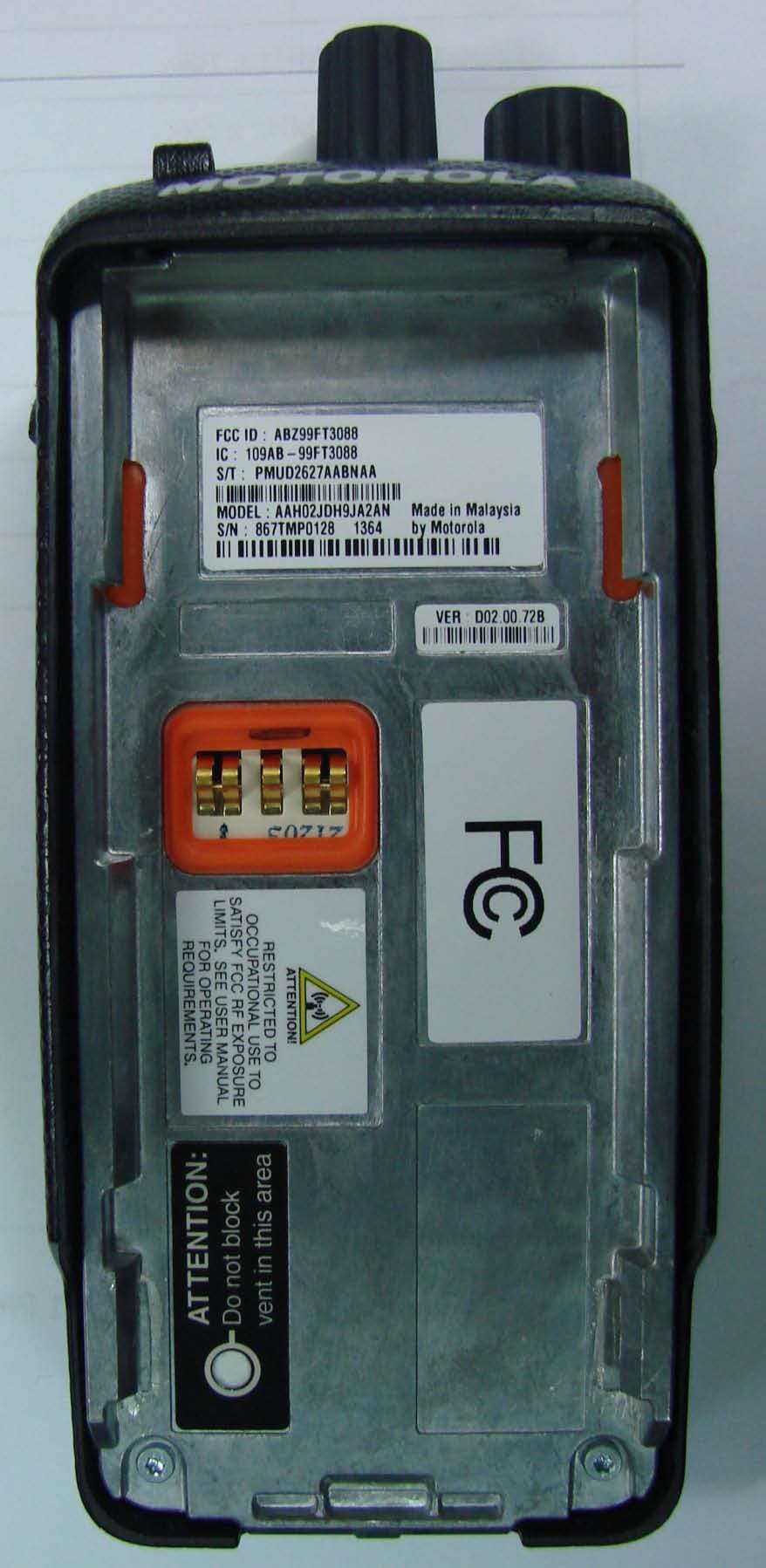
Click to zoom
Application Details
- Equipment Class
- TNF - Licensed Non-Broadcast Transmitter Held to Face
- Date of Grant
- May 21, 2012
- Application Purpose
- Original Equipment
- Date of Application
- Dec 20, 2011
- Equipment Note
- VHF Portable Radio
- Frequency Range
- 136.00000000 - 174.00000000
- Company
- Motorola Solutions, Inc.
- Country
- United States
Documents & Files
Document Text
Text extracted from the exhibit documents filed with the FCC. Open a document above to read the original.
Users Manual
M MOTOTRBO XPR TM 3500/3550 Limited Keypad Portable User Guide 68009512001-A LKP_NAG-LACR.book Page i Tues day, September 6, 2011 5:01 PM LKP_NAG-LACR.book Page ii Tues day, September 6, 2011 5:01 PM Declaration of Conformity English i Declaration of Conformity This declaration is applicable to your radio only if your radio is labeled with the FCC logo shown below. DECLARATION OF CONFORMITYPer FCC CFR 47 Part 2 Section 2.1077(a)Responsible Party Name: Motorola Solutions, Inc.Address: 1301 East Algonquin Road, Schaumburg, IL 60196-1078, U.S.A.Phone Number: 1-800-927-2744Hereby declares that the product: Model Name: XPR 3300/3350 conforms to the following regulations: FCC Part 15, subpart B, section 15.107(a), 15.107(d) and section 15.109(a) Class B Digital DeviceAs a personal computer peripheral, this device complies with Part 15 of the FC C Rules. Operation is subject to the following two conditions: 1. This device may not cause harmful interference, and 2. This device must accept any interference received, including interference that may cause undesired operation. LKP_NAG-LACR.book Page i Tues day, September 6, 2011 5:01 PM Declaration of Conformity English ii Note: This equipment has been tested and found to comply with the li mits for a Class B digital device, pursuant to part 15 of the FCC Rules. These limits are designed to provi de reasonable protection against harmful interference in a residential installation. This equipment generates, us es and can radiate radio frequency energy and, if not installed and used in accordance with the instructions, may cause harmful interference to radio communications. However, there is no guarantee that interference wi ll not occur in a particular installation. If this equipment does cause harmful interference to radi o or television reception, which can be determined by turning the equipment off and on, the user is encouraged to try to correct the interference by one or more of the following measures: • Reorient or relocate the receiving antenna. • Increase the separation between the equipment and receiver. • Connect the equipment into an outlet on a circuit differ ent from that to which the receiver is connected. • Consult the dealer or an experienc ed radio/TV technician for help. LKP_NAG-LACR.book Page ii Tues day, September 6, 2011 5:01 PM English 1 ContentsThis User Guide contains all information you need to use the MOTOTRBO XPR 3500/3550 Digital Portable Radios.Declaration of Conformity . . . . . . . . . . . . . . . . . . . . . iImportant Safety Information . . . . . . . . . . . . . . . . . . 5 Product Safety and RF Exposure Compliance . . . 5 Firmware Version . . . . . . . . . . . . . . . . . . . . . . . . . . . . 5Computer Software Copyrights . . . . . . . . . . . . . . . . 6 Handling Precautions . . . . . . . . . . . . . . . . . . . . . . . . 7Notes . . . . . . . . . . . . . . . . . . . . . . . . . . . . . . . . . . . . . . 8 How to Use This Guide . . . . . . . . . . . . . . . . . . . . . . . 1What Your Dealer/System Administrator Can Tell You . . . . . . . . . . . . . . . . . . . . . . . . . . . . . . 1 Charging the Battery . . . . . . . . . . . . . . . . . . . . . . . . . 2 Attaching the Battery . . . . . . . . . . . . . . . . . . . . . . . . . 2Attaching the Antenna . . . . . . . . . . . . . . . . . . . . . . . . 3Attaching the Belt Clip . . . . . . . . . . . . . . . . . . . . . . . . 3Attaching the Universal Con nector Cover (Dust Cover) 4 Attaching the Accessory Connector . . . . . . . . . . . . . 4Powering Up the Radio . . . . . . . . . . . . . . . . . . . . . . . 5Adjusting the Volume . . . . . . . . . . . . . . . . . . . . . . . . 6 Radio Controls . . . . . . . . . . . . . . . . . . . . . . . . . . . . . 6Programmable Buttons . . . . . . . . . . . . . . . . . . . . . . . 7 Assignable Radio Functions . . . . . . . . . . . . . . . . . 8Assignable Settings or Utility Functions . . . . . . . . . 9 Accessing the Programmed Functions . . . . . . . . . . . 9Push-To-Talk (PTT) Bu tton . . . . . . . . . . . . . . . . . . . 10 Switching Between Conventional Analog and Digital Mode . . . . . . . . . . . . . . . . . . . . . . . . . . . . . . . . . . . 11 Capacity Plus . . . . . . . . . . . . . . . . . . . . . . . . . . . . . 11Display Icons . . . . . . . . . . . . . . . . . . . . . . . . . . . . . . 12Call Icons . . . . . . . . . . . . . . . . . . . . . . . . . . . . . . . . 13 Advanced Menu Icons . . . . . . . . . . . . . . . . . . . . . . 13 Mini Notice Icons . . . . . . . . . . . . . . . . . . . . . . . . . . 14LED Indicator . . . . . . . . . . . . . . . . . . . . . . . . . . . . . 14Audio Tones . . . . . . . . . . . . . . . . . . . . . . . . . . . . . . 15Indicator Tones . . . . . . . . . . . . . . . . . . . . . . . . . . . . 16 Making and Receiving Calls . . . . . . . . . . . . . . . . . . 16 Selecting a Site . . . . . . . . . . . . . . . . . . . . . . . . . . . 16Selecting a Zone . . . . . . . . . . . . . . . . . . . . . . . . . . . 17Selecting a Radio Channel, Subscriber ID, or Group ID . . . . . . . . . . . . . . . . . . . . . . . . . . . . . . 17 Receiving and Responding to a Radio Call . . . . . . 18 Receiving and Responding to a Group Call . . . . . 18Receiving and Responding to a Private Call . . . 19 Receiving an All Call . . . . . . . . . . . . . . . . . . . . . . 20 LKP_NAG-LACR.book Page 1 Tuesday, September 6, 2011 5:01 PM English 2 Receiving and Responding to a Selective Call . 21 Making a Radio Call . . . . . . . . . . . . . . . . . . . . . . . . 22 Making a Call with the Channel Selector Knob . . 22 Making a Selective Call . . . . . . . . . . . . . . . . . . . 24Making a Call with the One Touch Access Button . . . . . . . . . . . . . . . . . . . . . . . . . . . . . . . . . 25 Stopping a Radio Call . . . . . . . . . . . . . . . . . . . . . . 26Talkaround . . . . . . . . . . . . . . . . . . . . . . . . . . . . . . . 26Monitoring Features . . . . . . . . . . . . . . . . . . . . . . . . 27 Monitoring a Channel . . . . . . . …
Text truncated - open the document above for the full version.
Users Manual
m XPR TM 3000 Series Quick Reference Guide and Safety Manual 1 English Regulatory Compliance and Product Safety for Portable Two-Way Radios BEFORE USING THIS RADIO, READ THIS BOOKLET WHICH CONTAINS IMPORTANT OPERATING INSTRUCTIONS FOR SAFE USAGE AND RF ENERGY AWARENESS AND CONTROL INFORMATION AND OPERATIONAL INSTRUCTIONS FOR COMPLIANCE WITH RF ENERGY EXPOSURE LIMITS IN APPLICABLE NATIONAL AND INTERNATIONAL STANDARDS. ALSO READ THE OPERATIONAL INSTRUCTIONS FOR SAFE USAGE. FOR RADIOS THAT HAVE BEEN APPROVED AS INTRINSICALLY SAFE, READ THE INSTRUCTIONS AND INFORMATION ON INTRINSIC SAFETY ON PAGE 12 OF THIS BOOKLET. C a u t i o n 2 English RF Energy Exposure Awareness and Control Information and Operational Instructions for Occupational Use NOTICE:This radio is intended for use in occupational/controlled conditions where users have full knowledge of their exposure and can exercise control over their exposure to meet the occupational limits in FCC and International standards. This radio device is NOT authorized for general population consumer use. This two-way radio uses electromagnetic energy in the radio frequency (RF) spectrum to provide communications between two or more users over a distance. It uses radio frequency (RF) energy or radio waves to send and receive calls. RF energy is one form of electromagnetic energy. Other forms include, but are not limited to, sunlight and x-rays. RF energy, however, should not be confused with these other forms of electromagnetic energy, which when used improperly, can cause biological damage. Very high levels of x-rays, for example, can damage tissues and genetic material. Experts in science, engineering, medicine, health, and industry work with organizations to develop standards for safe exposure to RF energy. These standards provide recommended levels of RF exposure for both workers and the general public. These recommended RF exposure levels include substantial margins of protection. All Motorola two-way radios are designed, manufactured, and tested to ensure they meet government-established RF exposure levels. In addition, manufacturers also recommend specific 3 English operating instructions to users of two-way radios. These instructions are important because they inform users about RF energy exposure and provide simple procedures on how to control it. Please refer to the following websites for more information on what RF energy exposure is and how to control your exposure to assure compliance with established RF exposure limits: http://www.fcc.gov/oet/rfsafety/rf-faqs.html http://www.osha.gov/SLTC/radiofrequencyradiation/ index.htm l Federal Communication Commission (FCC) Regulations The FCC rules require manufacturers to comply with the FCC RF energy exposure limits for portable two- way radios before they can be marketed in the U.S. When two-way radios are used as a consequence of employment, the FCC requires users to be fully aware of and able to control their exposure to meet occupational requirements. Exposure awareness can be facilitated by the use of a product label directing users to specific user awareness information. Your Motorola two-way radio has a RF Exposure Product Label. Also, your Motorola user manual, or separate safety booklet includes information and operating instructions required to control your RF exposure and to satisfy compliance requirements. Compliance with RF Exposure Standards Your Motorola two-way radio is designed and tested to comply with a number of national and International standards and guidelines (listed below) for human exposure to radio frequency electromagnetic energy. 4 English This radio complies with the IEEE (FCC) and ICNIRP exposure limits for occupational/ controlled RF exposure environments at operating duty factors of up to 50% talk-50% listen and is authorized by the FCC for occupational use only. In terms of measuring RF energy for compliance with these exposure guidelines, your radio generates measurable RF energy only while it is transmitting (during talking), not when it is receiving (listening) or in standby mode. NOTE:The approved batteries, supplied with this radio, are rated for a 5-5-90 duty factor (5% talk-5% listen-90% standby) even though this radio complies with FCC occupational exposure limits and may operate at duty factors of up to 50% talk. Your Motorola two-way radio complies with the following RF energy exposure standards and guidelines: • United States Federal Communications Commission (FCC), Code of Federal Regulations; 47 CFR et seq. • FCC, OET Bulletin 65 • Institute of Electrical and Electronic Engineers (IEEE) C95.1 • International Commission on Non-Ionizing Radiation Protection (ICNIRP) • Ministry of Health (Canada) Safety Code 6 • Industry Canada RSS-102 • Australian Communications Authority Radiocommunications Standard et seq. • ANATEL ANNEX to Resolution No. 303 et seq. 5 English RF Exposure Compliance and Control Guidelines and Operating Instructions To control your exposure and ensure compliance with the occupational/controlled environment exposure limits, always adhere to the following procedures. Guidelines: • DO NOT remove the RF Exposure Label from the device. • User awareness instructions should accompany device when transferred to other users. • DO NOT use this device if the operational requirements described herein are not met. Operating Instructions • Transmit no more than the rated duty factor of 50% of the time. To transmit (talk), push the Push-To- Talk (PTT) button. To receive calls, release the PTT button. Transmitting 50% of the time, or less, is important because this radio generates measurable RF energy exposure only when transmitting (in terms of measuring for standards compliance). Two-Way Radio Operation • Hold the radio in a vertical position in front of the face with the microphone (and other parts of the radio including the antenna) at least one inch (2.5 centimeters) away from the nose or lips. Antenna should be kept away from the eye. Keeping…
Text truncated - open the document above for the full version.
External Photos
Applicant: Motorola Solutions Inc FCC ID: ABZ99FT3088 EXHIBIT 3 SHEET 1 OF 11 EXHIBIT 3 EXTERNAL PHOTOGRAPHS - Pursuant to 47 CFR 2.1033(c) 12 The following photographs are attached. 1. Front view (without antenna) 2. Front view (with Antenna) 3. Back view with battery 4. Back view without battery FCC label location 5. FCC label (Close view) 6. RF exposure label (Close view) 7. Bottom view 8. Side View (Left) PTT button side 9. Side View (right) side connector side 10. Top view With Antenna 11. Top view Without Antenna 12. Antenna (3 color code for 3 different frequency ranges) Applicant: Motorola Solutions Inc FCC ID: ABZ99FT3088 EXHIBIT 3 SHEET 2 OF 11 Front view (without Antenna) Applicant: Motorola Solutions Inc FCC ID: ABZ99FT3088 EXHIBIT 3 SHEET 3 OF 11 Front view (with Antenna) Applicant: Motorola Solutions Inc FCC ID: ABZ99FT3088 EXHIBIT 3 SHEET 4 OF 11 Back view (with battery) Applicant: Motorola Solutions Inc FCC ID: ABZ99FT3088 EXHIBIT 3 SHEET 5 OF 11 Back View without battery (FCC Label Location). Applicant: Motorola Solutions Inc FCC ID: ABZ99FT3088 EXHIBIT 3 SHEET 6 OF 11 FCC Label (Close View) RF Exposure Label (Close View) Applicant: Motorola Solutions Inc FCC ID: ABZ99FT3088 EXHIBIT 3 SHEET 7 OF 11 Bottom View Applicant: Motorola Solutions Inc FCC ID: ABZ99FT3088 EXHIBIT 3 SHEET 8 OF 11 Side View (Left) PTT button side Applicant: Motorola Solutions Inc FCC ID: ABZ99FT3088 EXHIBIT 3 SHEET 9 OF 11 Side View (Right) connector side Applicant: Motorola Solutions Inc FCC ID: ABZ99FT3088 EXHIBIT 3 SHEET 10 OF 11 TOP VIEW WITH Antenna Applicant: Motorola Solutions Inc FCC ID: ABZ99FT3088 EXHIBIT 3 SHEET 11 OF 11 TOP VIEW WITHOUT Antenna Antenna (3 color code for 3 different frequency ranges)
ID Label/Location Info
Applicant: Motorola Solutions Inc FCC ID: ABZ99FT3088 EXHIBIT 1 SHEET 1 OF 1 Identification Label LOCATION See the Attached Photograph or Sketch Top of Radio X Back of Radio under Belt Clip Back of Radio TYPE X sensitive adhesive backing. The adhesive is a permanent type acrylic The label is a polyester film laminate with a pressure with the minimum peel strength of 32 oz/inch. MARKINGS (TEXT) X location of the FCC label on the device. See the Attached Photograph and Exhibit 3-5 for the actual Label Attached Below. See Attached Drawing.
Internal Photos
Applicant: Motorola Solutions Inc FCC ID: ABZ99FT3088 EXHIBIT 9 SHEET 1 OF 7 Internal Photographs The following photographs are attached. Exhibit 1. MOTOTRBO VHF complete internal open up view 9A 2. MOTOTRBO VHF Chassis and RF board 9B 3. MOTOTRBO VHF RF board with Shields (Top) 9c 4. MOTOTRBO VHF RF board without Shields (Top) 9D 5. MOTOTRBO VHF RF board with Shields (Bottom) 9E 6. MOTOTRBO VHF RF board without Shields (Bottom) 9F Applicant: Motorola Solutions Inc FCC ID: ABZ99FT3088 EXHIBIT 9 SHEET 2 OF 7 Exhibits 9A MOTOTRBO VHF complete internal open up view RF Port (for conducted measurement) Applicant: Motorola Solutions Inc FCC ID: ABZ99FT3088 EXHIBIT 9 SHEET 3 OF 7 Exhibits 9B MOTOTRBO VHF Chassis and RF boar RF Port (for conducted measurement) Applicant: Motorola Solutions Inc FCC ID: ABZ99FT3088 EXHIBIT 9 SHEET 4 OF 7 Exhibits 9C MOTOTRBO VHF RF board with Shields (Top) RF Port (for conducted measurement) Applicant: Motorola Solutions Inc FCC ID: ABZ99FT3088 EXHIBIT 9 SHEET 5 OF 7 Exhibits 9D MOTOTRBO VHF RF board without Shields (Top) RF Port (for conducted measurement) Applicant: Motorola Solutions Inc FCC ID: ABZ99FT3088 EXHIBIT 9 SHEET 6 OF 7 Exhibits 9E MOTOTRBO VHF RF board with Shields (Bottom) Applicant: Motorola Solutions Inc FCC ID: ABZ99FT3088 EXHIBIT 9 SHEET 7 OF 7 Exhibits 9F MOTOTRBO VHF RF board without Shields (Bottom)
RF Exposure Info
SR9692 EMS EME Form-SAR-Rpt Ex7B-Rev. 2.01 Page 1 of 22 TESTING CERT # 2518.05 Exhibit 7B: SAR Test Report Photographs Enterprise Mobility Solutions EME Test Laboratory Motorola Solutions Malaysia Sdn Bhd (455657-H) Customer Solution Center Plot 2, Bayan Lepas Technoplex Industrial Park, Mukim 12 SWD 11900 Bayan Lepas Penang, Malaysia. Deanna M. Zakharia EMS EME Lab Senior Resource Manager, Laboratory Director Approval Date: 8/29/2011 SR9692 EMS EME Form-SAR-Rpt Ex7B-Rev. 2.01 Page 2 of 22 Exhibit 7B Revision History Date Revision Comments 8/18/11 O Initial release SR9692 EMS EME Form-SAR-Rpt Ex7B-Rev. 2.01 Page 3 of 22 1.0 Highest SAR Test Position per body location 1.1 Body DUT w/ antenna PMAD4121A offered battery PMNN4416A, audio cable PMLN5727A and body worn accessory PMLN4651A against the phantom. Same position used for the other offered antennas (see table below) and batteries. Battery kit # Separation Distances (mm) Antenna kit # @ bottom surface of the DUT @ antenna`s base @ antenna`s tip PMAD4116A PMNN4416A 5 37 54 PMAD4117A PMNN4416A 5 37 54 PMAD4118A PMNN4416A 5 37 54 PMAD4120A PMNN4416A 5 37 45 PMAD4121A PMNN4416A 5 37 45 PMAD4121A PMNN4417A 5 37 46 PMAD4121A PMNN4418A 6 42 52 PMAD4121A PMNN4415A 6 42 52 PMAD4119A PMNN4416A 5 37 45 SR9692 EMS EME Form-SAR-Rpt Ex7B-Rev. 2.01 Page 4 of 22 1.2 Face DUT w/ front side separated 2.5cm from phantom with antenna PMAD4121A and battery PMNN4416A. Same position used for the other offered antennas (see table below) and batteries. 1.3 Head Not Applicable 1.4 Hand Not Applicable Battery kit # Separation Distances (mm) Antenna kit # @ bottom surface of the DUT @ antenna`s base @ antenna`s tip PMAD4116A PMNN4416A 31 31 37 PMAD4117A PMNN4416A 31 31 37 PMAD4118A PMNN4416A 31 31 37 PMAD4120A PMNN4416A 31 31 33 PMAD4121A PMNN4416A 31 31 33 PMAD4121A PMNN4418A 31 31 33 PMAD4121A PMNN4417A 31 31 33 PMAD4121A PMNN4415A 31 31 33 PMAD4119A PMNN4416A 31 31 33 SR9692 EMS EME Form-SAR-Rpt Ex7B-Rev. 2.01 Page 5 of 22 2.0 Other SAR tested positions at the body 2.1 Body worn DUT w/ antenna PMAD4116A, battery PMNN4416A and body worn HLN6602A attached, audio cable PMLN5727A against the phantom. Same position used for the other offered antennas (see table below) and batteries. Battery kit # Separation Distances (mm) Antenna kit # @ bottom surface of the DUT @ antenna`s base @ antenna`s tip PMAD4116A PMNN4416A 3 29 22 PMNN4417A 3 29 22 PMNN4418A 3 34 20 PMNN4415A 3 34 20 PMAD4117A PMNN4416A 3 29 22 PMAD4118A PMNN4416A 3 29 22 PMAD4120A PMNN4416A 3 29 31 PMAD4121A PMNN4416A 3 29 31 SR9692 EMS EME Form-SAR-Rpt Ex7B-Rev. 2.01 Page 6 of 22 DUT w/ antenna PMAD4116A, battery PMNN4416A, audio cable PMLN5727A and body worn PMLN5863A against the phantom. Same position used for the other offered antennas (see table below) and batteries. Battery kit # Separation Distances (mm) Antenna kit # @ bottom surface of the DUT @ antenna`s base @ antenna`s tip PMAD4116A PMNN4416A 0 62 108 PMAD4117A PMNN4416A 0 62 108 PMAD4118A PMNN4416A 0 62 108 PMAD4120A PMNN4416A 0 62 89 PMAD4121A PMNN4416A 0 62 89 PMAD4116A PMNN4417A 0 62 108 PMAD4116A PMNN4418A 0 67 115 PMAD4116A PMNN4415A 0 67 115 SR9692 EMS EME Form-SAR-Rpt Ex7B-Rev. 2.01 Page 7 of 22 DUT w/ antenna PMAD4116A, battery PMNN4416A, audio cable PMLN5727A and body worn PMLN5865A against the phantom. Same position used for the other offered antennas (see table below) and batteries. Battery kit # Separation Distances (mm) Antenna kit # @ bottom surface of the DUT @ antenna`s base @ antenna`s tip PMAD4116A PMNN4416A 15 69 104 PMAD4117A PMNN4416A 15 69 104 PMAD4118A PMNN4416A 15 69 104 PMAD4120A PMNN4416A 15 69 85 PMAD4121A PMNN4416A 15 69 85 PMAD4117A PMNN4417A 15 69 104 PMAD4117A PMNN4418A 11 75 119 PMAD4117A PMNN4415A 11 75 119 SR9692 EMS EME Form-SAR-Rpt Ex7B-Rev. 2.01 Page 8 of 22 DUT w/ antenna PMAD4121A, battery PMNN4416A, audio cable PMLN5727A and body worn PMLN5869A against the phantom. Same position used for the other offered antennas (see table below) and batteries. Battery kit # Separation Distances (mm) Antenna kit # @ bottom surface of the DUT @ antenna`s base @ antenna`s tip PMAD4116A PMNN4416A 2 37 52 PMAD4117A PMNN4416A 2 37 52 PMAD4118A PMNN4416A 2 37 52 PMAD4120A PMNN4416A 2 37 42 PMAD4121A PMNN4416A 2 37 42 PMAD4121A PMNN4417A 2 37 42 PMAD4121A PMNN4418A 3 41 47 PMAD4121A PMNN4415A 3 41 47 SR9692 EMS EME Form-SAR-Rpt Ex7B-Rev. 2.01 Page 9 of 22 DUT w/ antenna PMAD4116A, battery PMNN4416A, audio cable PMLN5727A and body worn PMLN5867A against the phantom. Same position used for the other offered antennas (see table below) and batteries. Battery kit # Separation Distances (mm) Antenna kit # @ bottom surface of the DUT @ antenna`s base @ antenna`s tip PMAD4116A PMNN4416A 11 72 117 PMAD4117A PMNN4416A 11 72 117 PMAD4118A PMNN4416A 11 72 117 PMAD4120A PMNN4416A 7 72 101 PMAD4121A PMNN4416A 7 72 101 PMAD4117A PMNN4417A 7 72 101 PMAD4117A PMNN4418A 10 75 126 PMAD4117A PMNN4415A 11 72 117 SR9692 EMS EME Form-SAR-Rpt Ex7B-Rev. 2.01 Page 10 of 22 DUT w/ antenna PMAD4116A, battery PMNN4416A, audio cable PMLN5727A and body worn PMLN7008A against the phantom. Same position used for the other offered antennas (see table below) and batteries. Battery kit # Separation Distances (mm) Antenna kit # @ bottom surface of the DUT @ antenna`s base @ antenna`s tip PMAD4116A PMNN4416A 5 37 57 PMAD4117A PMNN4416A 5 37 55 PMAD4118A PMNN4416A 5 37 55 PMAD4120A PMNN4416A 5 37 46 PMAD4121A PMNN4416A 5 37 47 PMAD4116A PMNN4417A 5 37 57 PMAD4116A PMNN4418A 6 42 62 PMAD4116A PMNN4415A 5 41 60 SR9692 EMS EME Form-SAR-Rpt Ex7B-Rev. 2.01 Page 11 of 22 DUT w/ antenna PMAD4116A, battery PMNN4416A, audio cable PMLN5727A and body worn RLN4570A against the phantom. Same position used for the other offered antennas (see table below) and batteries. Battery kit # Separation Distances (mm) Antenna kit # @ bottom surface of the DUT @ antenna`s base @ antenna`s tip PMAD4116A PMNN4416A 0 28 23 PMAD4117A PMNN4416A 0 28 23 PMAD4118A PMNN4416A 0 28 23 PMAD4120A PM…
Text truncated - open the document above for the full version.
RF Exposure Info
SR9692 Motorola Solutions EME Form-SAR-Rpt-Rev. 11.0 Page 1 of 65 TESTING CERT # 2518.05 DECLARATION OF COMPLIANCE SAR ASSESSMENT Part 1 of 2 Enterprise Mobility Solutions EME Test Laboratory Motorola Solutions Malaysia Sdn Bhd (455657-H) Customer Solution Center Plot 2, Bayan Lepas Technoplex Industrial Park, Mukim 12 SWD 11900 Bayan Lepas Penang, Malaysia. Date of Report: 3/20/2012 Report Revision: B Report ID: SAR rpt_PMUD2627A_Rev.B 120320_SR9692 Responsible Engineer: Veeramani Veerapan (Senior EME Engineer) Report Author: Veeramani Veerapan (Senior EME Engineer) Date/s Tested: 7/16/11-8/01/11 Manufacturer/Location: Penang, Malaysia Sector/Group/Div.: EMS Date submitted for test: 6/28/11 DUT Description: 136-174 MHz, 5W, LKP Test TX mode(s): CW (PTT) Max. Power output: 6.0 W Nominal Power: 5.0 W Tx Frequency Bands: 136-174 MHz Signaling type: FM Model(s) Tested: PMUD2627A Model(s) Certified: PMUD2627A Serial Number(s): 867TMM0080, 867TMM0084 Classification: Occupational/Controlled FCC ID: ABZ99FT3088; Rule part 90 (150.8-173.4 MHz) IC: 109AB-99FT3088; (138-144; 148-149.9 and 150.05-174 MHz) * Refer to section 15 of part 1 for highest SAR summary results. The test results clearly demonstrate compliance with FCC Occupational/Controlled RF Exposure limits of 8 W/kg averaged over 1 gram per the requirements of 47 CFR 2.1093(d). The 10 grams result is not applicable to FCC filing. The test results clearly demonstrate compliance with ICNIRP (1998) Guidelines for limiting exposure in time-varying electric, magnetic, and electromagnetic fields (up to 300 GHz), Health Physics 74, 494-522 RF Exposure limits of 10 W/kg averaged over 10grams of contiguous tissue. Based on the information and the testing results provided herein, the undersigned certifies that when used as stated in the operating instructions supplied, said product complies with the national and international reference standards and guidelines listed in section 3.0 of this report. This report shall not be reproduced without written approval from an officially designated representative of the Motorola Solutions Inc EME Laboratory. I attest to the accuracy of the data and assume full responsibility for the completeness of these measurements. This reporting format is consistent with the suggested guidelines of the TIA TSB-150 December 2004. The results and statements contained in this report pertain only to the device(s) evaluated. Deanna Zakharia EMS EME Lab Senior Resource Manager, Laboratory Director Approval Date: 3/20/2012 Certification Date: 9/23/2011 Certification No.: L1110915P SR9692 Motorola Solutions EME Form-SAR-Rpt-Rev. 11.0 Page 2 of 65 Part 1 of 2 1.0 Introduction ..............................................................................................................4 2.0 Abbreviations / Definitions ......................................................................................4 3.0 Referenced Standards and Guidelines ......................................................................4 4.0 SAR Limits ..............................................................................................................5 5.0 SAR Result Scaling Methodology ...........................................................................6 6.0 Description of Device Under Test (DUT) ................................................................6 7.0 Optional Accessories and Test Criteria ....................................................................6 7.1 Antennas ......................................................................................................6 7.2 Batteries .......................................................................................................7 7.3 Body worn Accessories ................................................................................7 7.4 Audio Accessories .......................................................................................8 8.0 Description of Test System ......................................................................................8 8.1 Descriptions of Robotics/Probes/Readout Electronics ................................9 8.2 Description of Phantom(s) ...........................................................................9 8.2.1 Dual Flat Phantom ...........................................................................9 8.2.2 SAM Phantom ..................................................................................9 8.2.3 Elliptical Phantom ............................................................................9 8.3 Description of Simulated Tissue ..................................................................9 9.0 Additional Test Equipment ....................................................................................10 10.0 SAR Measurement System Verification ................................................................11 10.1 Equivalent Tissue Test Results ..................................................................11 10.2 System Check Test Results ........................................................................14 11.0 Environmental Test Conditions .............................................................................15 12.0 DUT Test Methodology .........................................................................................15 12.1 Measurements ............................................................................................15 12.2 DUT Configuration(s) ................................................................................15 12.3 DUT Positioning Procedures ....................................................................15 12.3.1 Body ............................................................................................16 12.3.2 Head ............................................................................................16 12.3.3 Face .............................................................................................16 12.4 DUT Test Cha…
Text truncated - open the document above for the full version.
RF Exposure Info
SR9692 Motorola Solutions EME Form-SAR-Rpt-Rev. 11.0 Page 1 of 60 TESTING CERT # 2518.05 DECLARATION OF COMPLIANCE SAR ASSESSMENT Part 2 of 2 Enterprise Mobility Solutions EME Test Laboratory Motorola Solutions Malaysia Sdn Bhd (455657-H) Customer Solution Center Plot 2, Bayan Lepas Technoplex Industrial Park, Mukim 12 SWD 11900 Bayan Lepas Penang, Malaysia. Date of Report: 3/20/2012 Report Revision: B Report ID: SAR rpt_PMUD2627A_Rev.B 120320_SR9692 Responsible Engineer: Veeramani Veerapan (Senior EME Engineer) Report Author: Veeramani Veerapan (Senior EME Engineer) Date/s Tested: 7/16/11-8/01/11 Manufacturer/Location: Penang, Malaysia Sector/Group/Div.: EMS Date submitted for test: 6/28/11 DUT Description: 136-174 MHz, 5W, LKP Test TX mode(s): CW (PTT) Max. Power output: 6.0 W Nominal Power: 5.0 W Tx Frequency Bands: 136-174 MHz Signaling type: FM Model(s) Tested: PMUD2627A Model(s) Certified: PMUD2627A Serial Number(s): 867TMM0080, 867TMM0084 Classification: Occupational/Controlled FCC ID: ABZ99FT3088; Rule part 90 (150.8-173.4 MHz) IC: 109AB-99FT3088; (138-144; 148-149.9 and 150.05-174 MHz) * Refer to section 15 of part 1 for highest SAR summary results. The test results clearly demonstrate compliance with FCC Occupational/Controlled RF Exposure limits of 8 W/kg averaged over 1 gram per the requirements of 47 CFR 2.1093(d). The 10 grams result is not applicable to FCC filing. The test results clearly demonstrate compliance with ICNIRP (1998) Guidelines for limiting exposure in time-varying electric, magnetic, and electromagnetic fields (up to 300 GHz), Health Physics 74, 494-522 RF Exposure limits of 10 W/kg averaged over 10grams of contiguous tissue. Based on the information and the testing results provided herein, the undersigned certifies that when used as stated in the operating instructions supplied, said product complies with the national and international reference standards and guidelines listed in section 3.0 of this report. This report shall not be reproduced without written approval from an officially designated representative of the Motorola Solutions Inc EME Laboratory. I attest to the accuracy of the data and assume full responsibility for the completeness of these measurements. This reporting format is consistent with the suggested guidelines of the TIA TSB-150 December 2004. The results and statements …
Text truncated - open the document above for the full version.
Contact Information
Applicant
Matthew Nawrocki
Technical Contact
Motorola Solutions, Inc.Larry D. Larsen
[email protected]847-538-2239
1301 E. Algonquin Rd. · Schaumburg, Illinois · United States
Test Firm
Timco Engineering, Inc.Bruno Clavier
Technical Specifications
| # | Rule Parts | Frequency Range | Power Output | Emission | Tolerance |
|---|---|---|---|---|---|
| 1 | 80,90,90.210,90.210(e) | 136 MHz - 174 MHz | 5 W | NOTE 1 | 1.5000000000 ppm |
Other Applications from Motorola Solutions, Inc.

ABZ89FT4940
Aug 06, 2026Non Broadcast Transmitter
Equipment Class
TNB - Licensed Non-Broadcast Station TransmitterABZ89FT4950
Jun 25, 2026Non-Broadcast Transmitter
Equipment Class
TNB - Licensed Non-Broadcast Station TransmitterABZ89FT5901
Jun 20, 2024Non Broadcast Transmitter
Equipment Class
TNB - Licensed Non-Broadcast Station Transmitter
ABZ99FT5101B
May 02, 2023Non Broadcast Transmitter
Equipment Class
PCB - PCS Licensed Transmitter
ABZ99FT3095B
Mar 26, 2023Non Broadcast Transmitter
Equipment Class
TNB - Licensed Non-Broadcast Station Transmitter