ABZ99FT3094Non Broadcast Transmitter
Motorola Solutions, Inc.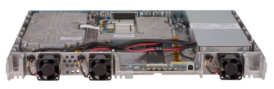
Click to zoom
Application Details
- Equipment Class
- TNB - Licensed Non-Broadcast Station Transmitter
- Date of Grant
- Mar 16, 2015
- Application Purpose
- Original Equipment
- Date of Application
- Mar 16, 2015
- Equipment Note
- Non Broadcast Transmitter
- Frequency Range
- 136.00000000 - 174.00000000
- Company
- Motorola Solutions, Inc.
- Country
- United States
Documents & Files
Document Text
Text extracted from the exhibit documents filed with the FCC. Open a document above to read the original.
External Photos
APPLICANT: MOTOROLA SOLUTIONS EQUIPMENT TYPE: ABZ99FT3094 109AB-99FT3094 EXHIBIT C1-1 Photographs of the Device External Front View of Base Radio APPLICANT: MOTOROLA SOLUTIONS EQUIPMENT TYPE: ABZ99FT3094 109AB-99FT3094 EXHIBIT C1-2 Photographs of the Device External Front View of Base Radio, Top Cover and Front Panel Removed APPLICANT: MOTOROLA SOLUTIONS EQUIPMENT TYPE: ABZ99FT3094 109AB-99FT3094 EXHIBIT C1-3 Photographs of the Device External Back View of Base Radio
ID Label/Location Info
APPLICANT: MOTOROLA SOLUTIONS EQUIPMENT TYPE: ABZ99FT3094 109AB-99FT3094 EXHIBIT A1 Equipment Label FCC / IC Identification Numbers The FCC Identifier (FCC ID) is made up of the Grantee Code, supplied by the FCC, and an Equipment Product Code. This equipment product code may be to 14 characters in length, and is assigned by the grantee (applicant). The Grantee Code for this product is ABZ The Equipment Product Code for this product is 99FT3094 The entire FCC ID number is ABZ99FT3094 The Industry Canada (IC) identification consists of the certification / registration number as well as the IC model number. The certification / registration number is made up of Company Number (CN) assigned by Industry Canada, and the Unique Product Number (UPN) assigned by Motorola. The IC model number is the unique model number of the radio assigned by Motorola. The Company Number is 109AB The Certification / Registration Number for this product is 109AB-99FT3094 The IC Model Number is SLR 5700-VHF APPLICANT: MOTOROLA SOLUTIONS EQUIPMENT TYPE: ABZ99FT3094 109AB-99FT3094 EXHIBIT A2-1 Equipment Label FCC / IC Identification Label A representative image of the FCC / IC Identification label is shown below. This label is generated as part of the standard manufacturing process and is printed in the factory. Much of the information that is on the label, such as serial number, model number, etc. is driven by the ordering process and is unique per customer order. MAC 1: 847E40FD1A22 MAC 2: 847E40FD1A23 SN: I.T.E. 31 NH Made in Mexico Ser ial No: 478IQY029 5 M odel No: AAR10JCGAPQ1AN S/Tanapa: PM UD3327ABANAA FCC ID: ABZ99FT3094 IC: 109AB- 99FT3094 IC Model No: SLR 5700-VHF 100- 240V ~ M ax 4A 50/60 Hz 11.0-14.4V 17A Max This device complies with Part 15 of the FCC rules. Operation is subject to the condition that this device does not cause harmful interference SLR 5700 FCC / IC Identification Label APPLICANT: MOTOROLA SOLUTIONS EQUIPMENT TYPE: ABZ99FT3094 109AB-99FT3094 EXHIBIT A2-2 Equipment Label FCC / IC ID Label The location of the identification label is on the back of the radio, as shown in the photograph below. Location of FCC/ IC Identification Label
Internal Photos
APPLICANT: MOTOROLA SOLUTIONS EQUIPMENT TYPE: ABZ99FT3094 109AB-99FT3094 EXHIBIT C2-1 Photographs of the Device Internal Front View – Modem Module APPLICANT: MOTOROLA SOLUTIONS EQUIPMENT TYPE: ABZ99FT3094 109AB-99FT3094 EXHIBIT C2-2 Photographs of the Device Internal Front View – Modem Module Top View – Cover Removed APPLICANT: MOTOROLA SOLUTIONS EQUIPMENT TYPE: ABZ99FT3094 109AB-99FT3094 EXHIBIT C2-3 Photographs of the Device Internal Front View – Modem Module Bottom View – Heat Sink Removed APPLICANT: MOTOROLA SOLUTIONS EQUIPMENT TYPE: ABZ99FT3094 109AB-99FT3094 EXHIBIT C2-4 Photographs of the Device Internal Front View – Power Amplifier Module APPLICANT: MOTOROLA SOLUTIONS EQUIPMENT TYPE: ABZ99FT3094 109AB-99FT3094 EXHIBIT C2-5 Photographs of the Device Internal Front View – Power Amplifier Module – Top View, Cover Removed APPLICANT: MOTOROLA SOLUTIONS EQUIPMENT TYPE: ABZ99FT3094 109AB-99FT3094 EXHIBIT C2-6 Photographs of the Device Internal Front View – Power Amplifier Module – Bottom View, Heat Sink Removed APPLICANT: MOTOROLA SOLUTIONS EQUIPMENT TYPE: ABZ99FT3094 109AB-99FT3094 EXHIBIT C2-7 Photographs of the Device Internal Front View – Power Supply Module
Test Report
APPLICANT: MOTOROLA SOLUTIONS EQUIPMENT TYPE: ABZ99FT3094 109AB-99FT3094 EXHIBIT E (Sheet 1 of 2) Report on Test Measurements Measurements Report The measurement report shows compliance information against the pertinent technical standards. Each parameter is measured generally at the low end, middle, and at the high end of the applicable frequency band. Each section of the report contains either verbiage or a graph (or graphs) which show compliance to applicable standards as required, explains testing method used, and indicates what the applicable specification is. Information and performance relative to 25 kHz ‘wideband’ operation is included in the report. Although wideband operation in the 150-174 MHz and 421-512 MHz bands is no longer allowable for rule part 90 in the US, it is available for other FCC rule parts and in use in other countries, including Industry Canada. The time division multiple access (TDMA) mode of operation provides two voice paths in a 12.5 kHz channel bandwidth and a data rate of 9600 bits per second bits per second in a channel bandwidth of 12.5 kHz. This is equivalent to one voice path per 6.25 kHz of channel bandwidth and 4800 bits per second or greater in a 6.25 kHz channel bandwidth. The SLR 5700 conforms to the spectrum efficiency requirements of FCC rule § 90.203 (j) (5). A list of test equipment for all sections, and certification signoff page are included at the end of the measurement report. SUBMITTED MEASURED DATA -- INDEX EXHIBIT DESCRIPTION E1-1 RF Output-Data E1-2 Occupied Bandwidth, Digital Emissions: Setup, Specifications, and Index E1-2.1 MOTOTRBO TM Digital Modulation, Low End of Band E1-2.2 MOTOTRBO TM Digital Modulation, Middle of Band E1-2.3 MOTOTRBO TM Digital Modulation, High End of Band E1-3 Conducted Spurious Emissions: Setup, Specifications, and Index E1-3.1 Conducted Spurious Harmonic Emissions, Power 60 Watts E1-3.2 Conducted Spurious Harmonic Emissions, Power 1 Watt E1-3.3 Conducted Spurious Emission Spectrum, 60 Watts, Low End of Band E1-3.4 Conducted Spurious Emission Spectrum, 60 Watts, Middle of Band E1-3.5 Conducted Spurious Emission Spectrum, 60 Watts, High End of Band E1-4 Radiated Spurious Emissions: Setup, Specifications, and Index E1-4.1 Radiated Spurious Harmonic Emissions, Power 60 Watts E1-4.2 Radiated Spurious Harmonic Emissions, Power 1 Watt E1-5 Frequency Stability: Setup, Specifications, and Index E1-5.1 Frequency Stability Vs Temperature E1-5.2 Frequency Stability Vs Voltage (Continued) APPLICANT: MOTOROLA SOLUTIONS EQUIPMENT TYPE: ABZ99FT3094 109AB-99FT3094 EXHIBIT E (Sheet 2 of 2) Report on Test Measurements Measurements Report SUBMITTED MEASURED DATA – INDEX (Continued) EXHIBIT DESCRIPTION E1-6 Frequency Transient Behavior: Setup, Specifications, and Index E1-6.1, 2, 3 Frequency Transient Behavior, 25 kHz Channel Key-Up E1-6.4, 5, 6 Frequency Transient Behavior, 25 kHz Channel De-Key E1-6.7, 8, 9 Frequency Transient Behavior, 12.5 kHz Channel Key-Up E1-6.10, 11, 12 Frequency Transient Behavior, 12.5 kHz Channel De-key E1-7 Audio Frequency Response – Modulation Characteristics: Setup, Specifications, and Index E1-7.1, 2, 3 Audio Frequency Response – 25 kHz Channels E1-7.4, 5, 6 Audio Frequency Response – 12.5 kHz Channels E1-8 Audio Modulation Limiting – Modulation Characteristics: Setup, Specifications, and Index E1-8.1, 2, 3 Audio Modulation Limiting – 25 kHz Channels E1-8.4, 5, 6 Audio Modulation Limiting – 12.5 kHz Channels E1-9 Occupied Bandwidth Description – Analog Modulation: Setup, Specifications, and Index E1-9.1, 2, 3 Occupied Bandwidth Plots – Low End of Band – Tone / PL / DPL – 25 kHz Channels E1-9.4, 5, 6 Occupied Bandwidth Plots – Middle of Band – Tone / PL / DPL – 25 kHz Channels E1-9.7, 8, 9 Occupied Bandwidth Plots – High End of Band – Tone / PL / DPL – 25 kHz Channels E1-9.10, 11, 12 Occupied Bandwidth Plots – Low End of Band – Tone / PL / DPL – 12.5 kHz Channels E1-9.13, 14, 15 Occupied Bandwidth Plots – Middle of Band – Tone / PL / DPL – 12.5 kHz Channels E1-9.16, 17, 18 Occupied Bandwidth Plots – High End of Band – Tone / PL / DPL – 12.5 kHz Channels E1-11 Test Equipment Used E1-12 Statement of Certification APPLICANT: MOTOROLA SOLUTIONS EQUIPMENT TYPE: ABZ99FT3094 109AB-99FT3094 EXHIBIT E1-1 Report on Test Measurements RF Power Output Data The RF power output was measured with the indicated voltage applied to and current into the final RF amplifying device(s). The DC current indicated is the total for the final RF amplifier stage. Frequency Modulation Mode (Analog and Digital): 138 MHz 155 MHz 174 MHz Measured RF output 60 60 60 Watts DC Voltage, final RF amplifier stage/stages 13.6 13.6 13.6 Volts DC Current, final RF amplifier stage/stages 7.9 7.7 7.8 Amperes Input power for final RF amplifying device(s) 107 105 106 Watts Primary Radio Input Supply Voltage 120 120 120 Volts AC Minimum Measured RF output 1 1 1 Watts DC Voltage, final RF amplifier stage/stages 13.6 13.6 13.6 Volts Normal DC Current 1.5 1.5 1.5 Amperes Input power for final RF amplifying device(s) 20 20 20 Watts Primary Radio Input Supply Voltage 120 120 120 Volts AC APPLICANT: MOTOROLA SOLUTIONS EQUIPMENT TYPE: ABZ99FT3094 109AB-99FT3094 EXHIBIT E1-2 (Sheet 1 of 2) Report on Test Measurements Occupied Bandwidth – MOTOTRBO TM Digital Modulation, 12.5 kHz Channel Spacing MOTOTRBO TM Digital Modulation can be used in a system configuration based upon channel usage as described in Exhibit B. The ‘F7E’ and ‘FXE’ emission designators provide usage for telephony, the ‘F7D’ and ‘FXD’ designators provide usage for data / telecommand, and the ‘F7W’ designator provides for usage as a combination of telephony and telecommand. All are spectrally identical. The occupied bandwidth chart references the following setup and specification requirements. Modulation Type: MOTOTRBO TM Digital Modulation Emission Designator: 7K60F7W, 7K60F7D, 7K60F7E, 7K60FXD, 7K60FXE Channelization: 12.5 kHz Power Setting: 60 Watts Specification Requirement 47 CFR…
Text truncated - open the document above for the full version.
Contact Information
Applicant
Matthew Nawrocki
Non-Technical Contact
Motorola SolutionsBob Sarocka
[email protected]8475762084
Technical Specifications
| # | Rule Parts | Frequency Range | Power Output | Emission | Tolerance |
|---|---|---|---|---|---|
| 7 | 22,74,80,9 | 136 MHz - 174 MHz | 60 W | 7K60F7W | 2.5 ppm |
Other Applications from Motorola Solutions, Inc.

ABZ89FT4940
Aug 06, 2026Non Broadcast Transmitter
Equipment Class
TNB - Licensed Non-Broadcast Station TransmitterABZ89FT4950
Jun 25, 2026Non-Broadcast Transmitter
Equipment Class
TNB - Licensed Non-Broadcast Station TransmitterABZ89FT5901
Jun 20, 2024Non Broadcast Transmitter
Equipment Class
TNB - Licensed Non-Broadcast Station Transmitter
ABZ99FT5101B
May 02, 2023Non Broadcast Transmitter
Equipment Class
PCB - PCS Licensed Transmitter
ABZ99FT3095B
Mar 26, 2023Non Broadcast Transmitter
Equipment Class
TNB - Licensed Non-Broadcast Station Transmitter