ABZ99FT3094BNon Broadcast Transmitter
Motorola Solutions, Inc.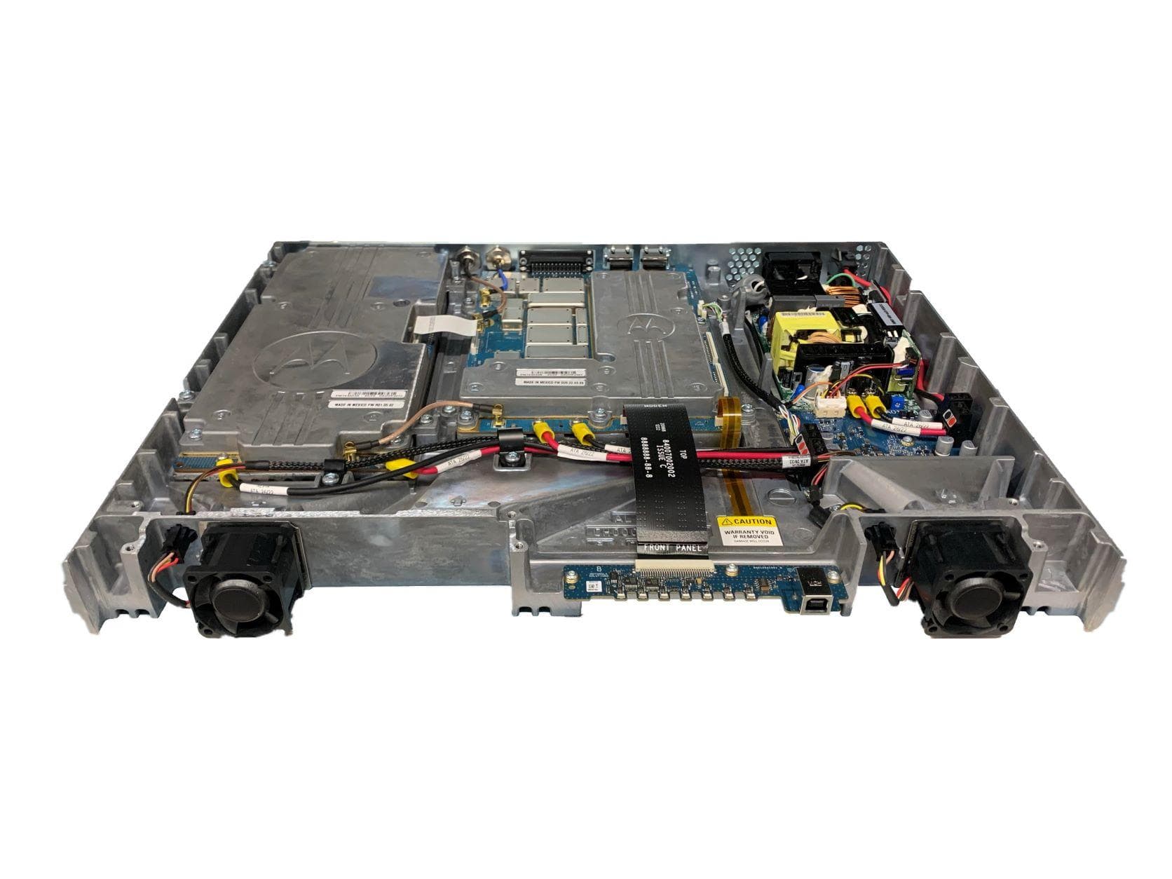
Click to zoom
Application Details
- Equipment Class
- TNB - Licensed Non-Broadcast Station Transmitter
- Date of Grant
- Jan 19, 2023
- Application Purpose
- Original Equipment
- Date of Application
- Jan 15, 2023
- Equipment Note
- Non Broadcast Transmitter
- Frequency Range
- 136.00000000 - 174.00000000
- Company
- Motorola Solutions, Inc.
- Country
- United States
Documents & Files
Document Text
Text extracted from the exhibit documents filed with the FCC. Open a document above to read the original.
Users Manual
EXHIBIT D User Information User Information Tune-up and user / operational manual information are provided in the following exhibits. EXHIBIT DESCRIPTION D1 Tune-Up Procedure D2 User / Operational Manual APPLICANT: MOTOROLA SOLUTIONS EQUIPMENT TYPE: ABZ99FT3094B 109AB-99FT3094B EXHIBIT D2 APPLICANT: MOTOROLA SOLUTIONS EQUIPMENT TYPE: ABZ99FT3094B 109AB-99FT3094B User / Operational Manual Operational or User’s Manual The manual should include instruction, installation, operator, or technical manuals with required ‘information to the users’. This manual should include a statement that cautions the user that changes or modifications not expressly approved by the party responsible for compliance could void the user’s authority to operate the equipment. The manual shall include RF Hazard warning statements, if applicable. The end user in the US and Canada receives a booklet entitled “MOTOTRBO™ SLR 5000 Series Repeater Quick Start Guide” (part number MN001440A01-AB, January 2023 , as all units are shipped with this document. This booklet is printed in English and French Canadian. As indicated in the ‘Quick Start Guide’, more detail can be found in the document “MOTOTRBO™ SLR 5000 Series Repeater Basic Service and Installation Manual” (part number MN001436A01-AJ, April 2020). Upon request, published basic service and installation manuals will be sent to the commission and/or telecommunication certification body (TCB). All of the descriptions, block diagrams, and schematics that are included in this filing package are current as of the package submittal date. MOTOTRBO ™ SLR 5000 Series Repeater Quick Start Guide January 2023 © 2022 Motorola Solutions, Inc. All rights reserved MN001440A01 MN001440A01-AB Notations Used in This Manual Note and caution notations are used throughout the text in this publication. These notations are used to emphasize that safety hazards exist, and due care must be taken and observed. Caution: Indicates a potentially hazardous situation which, if not avoided, might result in equipment damage. Warning: Indicates a potentially hazardous situation which, if not avoided, could result in death or injury. : Indicates areas of the product that pose potential burn hazards. General Safety and Installation Standards and Guidelines Warning: For safe installation, operation, service and repair of this equipment, follow the safety precautions and instructions described below, as well as any additional safety information in the Motorola Solutions product service and installation manuals and the Motorola Solutions R56 Standards and Guidelines for Communications Sites manual (which can be obtained by ordering CD-ROM 9880384V83). To obtain copies of these materials, contact Motorola Solutions as directed at the end of this section. After installation, these instructions should be retained and readily available for any person operating or servicing this repeater or working near it. Failure to follow these safety precautions and instructions could result in serious injury or property damage. The installation process requires preparation and knowledge of the site before the installation begins. Review installation procedures and precautions in the Motorola Solutions R56 manual before performing any site or component installation. Personnel must use safe work practices and good judgment, and always follow applicable safety procedures, such as requirements of the Occupational Safety and Health Administration (OSHA), the National Electrical Code (NEC), and local codes. The following are additional general safety precautions that must be observed: • To continue compliance with any applicable regulations and maintain the safety of this equipment, do not install substitute parts or perform any unauthorized modifications. • All equipment must be serviced by Motorola Solutions trained personnel. • If troubleshooting the equipment while the power is on, be aware of live circuits which could contain hazardous voltage. • Do not operate the radio transmitters unless all RF connectors are secure and all connectors are properly terminated. • All equipment must be properly grounded in accordance with the Motorola Solutions R56 and specified installation instructions for safe operation. • Slots and openings in the cabinet are provided for ventilation. Do not block or cover openings that protect the devices from overheating. • Some equipment components can become extremely hot during operation. Turn off all power to the equipment and wait until sufficiently cool before touching. • Maintain emergency first aid kits at the site. • Never store combustible materials in or near equipment racks. The combination of combustible material, heat and electrical energy increases the risk of a fire hazard. • Equipment should be installed in a site that meets the requirements of a “restricted access location,” per (UL60950-1, UL62368 & EN62368), which is defined as follows: “Access can only be gained by service persons or by users who have been instructed about the reasons for the restrictions applied to the location and about any precautions that shall be taken; and access is through the use of a tool or lock and key, or other means of security, and is controlled by the authority responsible for the location.” English 1 • Burn hazard. The metal housing of the product may become extremely hot. Use caution when working around the equipment. • RF energy burn hazard. Disconnect power in the cabinet to prevent injury before disconnecting and connecting antennas. • Shock hazard. The outer shields of all Tx and Rx RF cables outer shields must be grounded per the Motorola Solutions R56 manual. • Shock hazard. DC input voltage should be no higher than 60 VDC. This maximum voltage should include consideration of the battery charging “float voltage” associated with the intended supply system, regardless of the marked power rating of the equipment. • All Tx and Rx RF cables should be connected to a surge protection device accordin…
Text truncated - open the document above for the full version.
Cover Letter(s)
TO: Federal Communication Commission Equipment Authorization Division Application Processing Branch 7435 Oakland Mills Rd Columbia, MD 21046 ATTENTION: Federal Communication Commission Equipment Authorization To whom it may concern, We would like to submit for Certification to FCC: ABZ99FT3094B. Please find in the following application all related documentation to support this New Single Certification. We would appreciate your prompt attention to the submittal. Applicant Company name: Motorola Solutions, Inc. Contact Name: Bob Sarocka Address: 2000 Progress Parkway, Schaumburg, IL 60196 Telephone No: 847-344-6075 Email: [email protected] FCC ID Number: ABZ99FT3094B 12/14/22 Robert Sarocka Engineering Manager Motorola Solutions
Cover Letter(s)
FCC ID: ABZ99FT3094B HVIN: SLR5700-VHFB CONFIDENTIALITY REQUESTED Date: December 14. 2022 Pursuant to FCC 47 CFR 0.457(d) and 0.459 and IC RSP-100, the applicant requests that a part of the subject FCC application be held confidential. Type of Confidentiality Requested Exhibit Short Term Permanent Block Diagrams (Included in Exhibit B) Short Term External Photos Short Term Permanent Internal Photos Short Term Permanent Operation Description/Theory of Operation (Included in Exhibit B) Short Term Permanent Parts List & Placement/BOM (Included in Exhibit B) Short Term Permanent Tune-Up Procedure Short Term Permanent Schematics (Included in Exhibit B) Short Term Test Setup Photos Short Term Permanent* User’s Manual Motorola Solutions has spent substantial effort in developing this product and it is one of the first of its kind in industry. Having the subject information easily available to "competition" would negate the advantage they have achieved by developing this product. Not protecting the details of the design will result in financial hardship. Permanent Confidentiality: The applicant requests the exhibits listed above as permanently confidential be permanently withheld from public review due to materials that contain trade secrets and proprietary information not customarily released to the public. NOTE for Industry Canada Applications: The applicant understands that until such time that IC distinguishes between Short Term and Permanent Confidentiality, either type of marked exhibit above will simply be marked Confidential when submitted to IC. Sincerely, By: __________________________ Robert Sarocka (Signature) (Print name) Title: Engineering Manager
External Photos
APPLICANT: MOTOROLA SOLUTIONS EQUIPMENT TYPE: ABZ99FT3094B 109AB-99FT3094B Photographs of the Device EXHIBIT C Photographs – Index EXHIBIT DESCRIPTION C1-1 External Front View of Base Radio C1-2 External Front View of Base Radio, Top Cover and Front Panel Removed C1-3 External Back View of Base Radio C1-4 FCC / IC Identification Label C2-1 Internal – Modem Module C2-2 Internal – Modem Module Top View, Cover Removed C2-3 Internal – Modem Module Bottom View, Heat Sink Removed C2-4 Internal – Power Amplifier Module C2-5 Internal – Power Amplifier Module Top View, Cover Removed C2-6 Internal – Power Amplifier Module Bottom View, Heat Sink Removed C2-7 Internal – Power Supply Module, Top View C2-8 Internal – Power Supply Module, Bottom View C2-9 Internal – Peripheral Board, Top View C2-10 Internal – Peripheral Board, Bottom View APPLICANT: MOTOROLA SOLUTIONS EQUIPMENT TYPE: ABZ99FT3094B 109AB-99FT3094B Photographs of the Device EXHIBIT C1-1 External Front View of Base Radio APPLICANT: MOTOROLA SOLUTIONS EQUIPMENT TYPE: ABZ99FT3094B 109AB-99FT3094B Photographs of the Device EXHIBIT C1-2 External Front View of Base Radio, Top Cover and Front Panel Removed
ID Label/Location Info
APPLICANT: MOTOROLA SOLUTIONS EQUIPMENT TYPE: ABZ99FT3094B 109AB-99FT3094B Photographs of the Device EXHIBIT C1-4 FCC / IC Identification Label
ID Label/Location Info
APPLICANT: MOTOROLA SOLUTIONS EQUIPMENT TYPE: ABZ99FT3094B 109AB-99FT3094B Photographs of the Device EXHIBIT C1-3 External Back View of Base Radio
RF Exposure Info
Mot orola Solut ions Canada, Inc. UPN Number: 3 7 9 0 B Company Number: 1 0 9 AB HVIN: SLR 5700-VHFB Page 1 RF Exposure Technical Brief This Technical Brief calculates the minimum separation distance from an antenna, connected to the subject base station, such that the power density value listed in RSS-102, Radio Frequency (RF) Exposure Compliance of Radio communications Apparatus (All Frequency Bands) Issue 5 Table 6 is not exceeded. The analysis is for a typical installation using a structure mounted antenna. Within the frequency range that the subject equipment operates, 138 MHz – 174 MHz the permitted exposure limit is frequency dependent per the equation 0.6455*sqrt(f). Table 1 lists the maximum permitted exposure limits for the lowest and highest operating frequencies. The smaller maximum permissible exposure limit will be used for the computation because it requires a larger separation distance from the antenna to the exposed person. Table 1 - Maximum Permissible Exposure Limits Controlled Environment Frequency 138 MHz 174 MHz Limit 7.6 W/m 2 8.5 W/m 2 Example Calculations for GTR8000, UHF Transmitter: The example configuration is a single frequency site, with minimal RF network losses, set to zero for this example, between the transmitter output connector and the antenna input connector. The antenna has an omni directional pattern in the horizontal plane. Table 2 lists the key RF system and antenna parameters. Table 2 - Transmitter Configuration Frequency 138-174 MHz Base Station Output Power 60 W RF Network Loss 0 dB Antenna Type DS1F00F36U-D 0 dBd / 2.1 dBi (Omni) Antenna length 2.5 m Controlled Environment: Cylindrical Method 1 Using Equation 1 the spatially averaged plane-wave equivalent power density parallel to the antenna in the vertical plane is estimated by dividing the net input power to the antenna by the surface area of an imaginary cylinder at a distance R from the antenna, with the height of the cylinder equal to the length of the antenna 2 . Rh Pnet S 2 (1) 1 Federal Communications Commission Office of Engineering & Technology, OET Bulletin 65, “Evaluating Compliance with FCC Guidelines for Human Exposure to Radiofrequency Electromagnetic Fields”, Edition 97-01, page 32, Tell’s cylindrical model. 2 Federal Communications Commission Office of Engineering & Technology, OET Bulletin 65, “Evaluating Compliance with FCC Guidelines for Human Exposure to Radiofrequency Electromagnetic Fields”, Edition 97-01, page 32, Tell’s cylindrical model. Mot orola Solut ions Canada, Inc. UPN Number: 3 7 9 0 B Company Number: 1 0 9 AB HVIN: SLR 5700-VHFB Page 2 Where: S = power density, W/m 2 Pnet = net input power to the antenna, W R = radial distance from the antenna, m h = height of the antenna, m The minimum separation distance can be found by solving Equation 1 for R and setting S to the smaller maximum power density for the environment per Table 1. 50.0 5.26.72 60 2 xhS Pnet R m (2) For the example site configuration the minimum separation distance for a controlled environment is 0.50 m.
Contact Information
Applicant
Matthew Nawrocki
Technical Contact
Motorola Solutions, Inc.Robert Sarocka
[email protected]8473446075
2000 Progress Parkway · Schaumburg · United States
Non-Technical Contact
Motorola Solutions, Inc.Jerry Flondro
[email protected]8473446075
Test Firm
Elite Electronic Engineering Inc.Kevin Halpin
Technical Specifications
| # | Rule Parts | Frequency Range | Power Output | Emission | Tolerance |
|---|---|---|---|---|---|
| 7 | 22,74,80,9 | 136 MHz - 174 MHz | 60 W | 7K60F7W | 2.5 ppm |
Other Applications from Motorola Solutions, Inc.

ABZ89FT4940
Aug 06, 2026Non Broadcast Transmitter
Equipment Class
TNB - Licensed Non-Broadcast Station TransmitterABZ89FT4950
Jun 25, 2026Non-Broadcast Transmitter
Equipment Class
TNB - Licensed Non-Broadcast Station TransmitterABZ89FT5901
Jun 20, 2024Non Broadcast Transmitter
Equipment Class
TNB - Licensed Non-Broadcast Station Transmitter
ABZ99FT5101B
May 02, 2023Non Broadcast Transmitter
Equipment Class
PCB - PCS Licensed Transmitter
ABZ99FT3095B
Mar 26, 2023Non Broadcast Transmitter
Equipment Class
TNB - Licensed Non-Broadcast Station Transmitter