ABZ99FT4046M1225 Low Power Mobile
Motorola Solutions, Inc.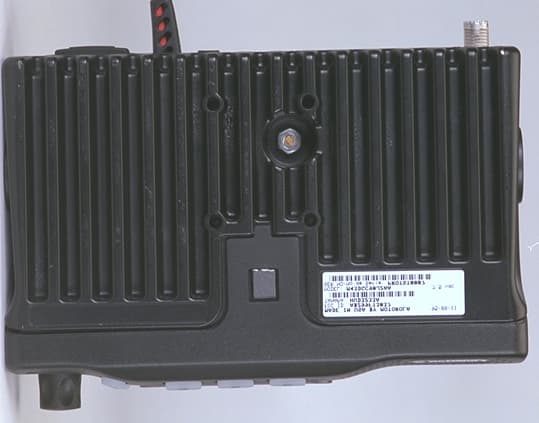
Click to zoom
Application Details
- Equipment Class
- TNB - Licensed Non-Broadcast Station Transmitter
- Date of Grant
- Apr 05, 1999
- Application Purpose
- Original Equipment
- Date of Application
- Feb 04, 1999
- Equipment Note
- M1225 Low Power Mobile
- Frequency Range
- 450.00000000 - 474.00000000
- Company
- Motorola Solutions, Inc.
- Country
- United States
Documents & Files
Document Text
Text extracted from the exhibit documents filed with the FCC. Open a document above to read the original.
Users Manual
TX CH1 CH2 CH3 CH4 Operator Guide for the 4-Channel M1225 Mobile Radio Copyright © 1999 Motorola, Inc. All rights reserved 6880906Z68-O This product is covered by one or more issued U.S. Patents. Other Patent applications pending. , MOTOROLA, and RADIUS are registered trademarks of Motorola, Inc. M1225 is a trademark of Motorola, Inc. English-1 Introduction. . . . . . . . . . . . . . . . . . . . . . . . . . . . . . . . . . . . . . . . . . . . . . . . . . . . . . . . . . . . . . 2 Safe Mounting of the Radio . . . . . . . . . . . . . . . . . . . . . . . . . . . . . . . . . . . . . . . . . . . . . . . 2 Controls and Visual Indicators . . . . . . . . . . . . . . . . . . . . . . . . . . . . . . . . . . . . . . . . . . . . . . 3 Basic Operating Instructions . . . . . . . . . . . . . . . . . . . . . . . . . . . . . . . . . . . . . . . . . . . . . . . 4 Set Volume. . . . . . . . . . . . . . . . . . . . . . . . . . . . . . . . . . . . . . . . . . . . . . . . . . . . . . . . . . . .4 Select a Channel . . . . . . . . . . . . . . . . . . . . . . . . . . . . . . . . . . . . . . . . . . . . . . . . . . . . . . . 4 Receive . . . . . . . . . . . . . . . . . . . . . . . . . . . . . . . . . . . . . . . . . . . . . . . . . . . . . . . . . . . . . . 4 Transmit . . . . . . . . . . . . . . . . . . . . . . . . . . . . . . . . . . . . . . . . . . . . . . . . . . . . . . . . . . . . . . 5 Monitor On-Off / Volume Set . . . . . . . . . . . . . . . . . . . . . . . . . . . . . . . . . . . . . . . . . . . . . . 5 Standard Programmable Features . . . . . . . . . . . . . . . . . . . . . . . . . . . . . . . . . . . . . . . . . . . 7 Time-Out Timer (T.O.T.) . . . . . . . . . . . . . . . . . . . . . . . . . . . . . . . . . . . . . . . . . . . . . . . . . . 7 Busy Channel Lockout . . . . . . . . . . . . . . . . . . . . . . . . . . . . . . . . . . . . . . . . . . . . . . . . . . . 7 Scan . . . . . . . . . . . . . . . . . . . . . . . . . . . . . . . . . . . . . . . . . . . . . . . . . . . . . . . . . . . . . . . . . 7 Option Button Programmable Features. . . . . . . . . . . . . . . . . . . . . . . . . . . . . . . . . . . . . . . 9 Repeater/Talkaround . . . . . . . . . . . . . . . . . . . . . . . . . . . . . . . . . . . . . . . . . . . . . . . . . . . . 9 Local/Distance . . . . . . . . . . . . . . . . . . . . . . . . . . . . . . . . . . . . . . . . . . . . . . . . . . . . . . . . .9 Telephone Access/Deaccess . . . . . . . . . . . . . . . . . . . . . . . . . . . . . . . . . . . . . . . . . . . . . . 9 Advantage™ Board Enable/Disable. . . . . . . . . . . . . . . . . . . . . . . . . . . . . . . . . . . . . . . . 10 Hi/Low Power . . . . . . . . . . . . . . . . . . . . . . . . . . . . . . . . . . . . . . . . . . . . . . . . . . . . . . . . . 10 Horn and Lights On/Off . . . . . . . . . . . . . . . . . . . . . . . . . . . . . . . . . . . . . . . . . . . . . . . . . 10 Troubleshooting . . . . . . . . . . . . . . . . . . . . . . . . . . . . . . . . . . . . . . . . . . . . . . . . . . . . . . . . . 11 Table of Contents 2-English This operator guide contains the information needed to identify the controls and visual indicators, operation, and troubleshooting for the M1225 mobile radio. Information about the radio’s visual and audible indicators ishighlighted and illustrated with icons. Information about radio safety, mounting, licensing, and other issues to be consideredbefore operating the radio are contained in the M1225 Installa- tion/Licensing Guide (Motorola part number 6880905Z15). The guide should be included in the shipment with your radio. If you need a replacement of the Installation/Licensing Guide or this Operator Guide, please contact your local Motorola Radius dealer. Read this information before using your mobile radio. For the safe and effi- cient operation of your mobile radio, observe these guidelines. Read this information before using your mobile radio. For the safe and efficient operation of your mobile radio, observe these guidelines. We have organized this manual to help you locate important information. The following icons signal specific types of information: Information about the radio’s signalling sounds (tones). Information about the radio’s signalling lights (LEDs). Safe Mounting of the Radio CAUTION:The bottom surface of the radio can become hot. Avoid contact during prolonged use. Do not mount where the bottom surface can come in contact with skin. Introduction English-3 TXCH1CH2CH3CH4 TXCH1CH2CH3CH4 Controls A. On/Off/Volume Knob B. Channel Up/Down Button C. Scan Button D.Monitor Button E. Option Buttons (A & B) F. Microphone Push-To-Talk (PTT) Button Visual Indicators 1. Light-Emitting Diode (LED) 2. Transmit / Receive Icon 3. Monitor Icon 4.Channel LEDs 5. Option Icons A C B E F 1 Controls and Visual Indicators D 2 5 3 4 4-English Turn the Radio On/Off Turn the on/off/volume knob until it clicks. A short, high-pitched tone sounds, indicator successful start-up. If the radio is not operating properly, a continuous low-pitched alert tone sounds. Set Volume Turn the On/Off/Volume knob to adjust the volume to a comfortable listen- ing level. Select a Channel Pressorto select the desired channelorpress and hold to scroll through the channels. A short, high-pitched tone (“good key press”) sounds each time you press or, or when the radio scrolls to the next channel. A medium-pitched tone sounds upon returning to the first channel. Receive Press or to select the desired channelor press and hold to scroll through the channels. Make sure the PTT is released. Listen for voice activity. The receive icon blinks when the radio is receiving. 1 1 1 1 2 Basic Operating Instructions English-5 Transmit NOTE: In the United States, FCC regulations require you to monitor the channel before you transmit. Refer to the Programmable Options section of this manual for Monitor instructions. Press the PTT. The transmit icon lights on the display during transmission. The LED on the microphone also glows red while you are transmittin…
Text truncated - open the document above for the full version.
Users Manual
TX CH1 CH2 CH3 CH4 Operator Guide for the 4-Channel M1225 Mobile Radio Copyright © 1999 Motorola, Inc. All rights reserved 6880906Z68-O This product is covered by one or more issued U.S. Patents. Other Patent applications pending. , MOTOROLA, and RADIUS are registered trademarks of Motorola, Inc. M1225 is a trademark of Motorola, Inc. English-1 Introduction. . . . . . . . . . . . . . . . . . . . . . . . . . . . . . . . . . . . . . . . . . . . . . . . . . . . . . . . . . . . . . 2 Safe Mounting of the Radio . . . . . . . . . . . . . . . . . . . . . . . . . . . . . . . . . . . . . . . . . . . . . . . 2 Controls and Visual Indicators . . . . . . . . . . . . . . . . . . . . . . . . . . . . . . . . . . . . . . . . . . . . . . 3 Basic Operating Instructions . . . . . . . . . . . . . . . . . . . . . . . . . . . . . . . . . . . . . . . . . . . . . . . 4 Set Volume. . . . . . . . . . . . . . . . . . . . . . . . . . . . . . . . . . . . . . . . . . . . . . . . . . . . . . . . . . . .4 Select a Channel . . . . . . . . . . . . . . . . . . . . . . . . . . . . . . . . . . . . . . . . . . . . . . . . . . . . . . . 4 Receive . . . . . . . . . . . . . . . . . . . . . . . . . . . . . . . . . . . . . . . . . . . . . . . . . . . . . . . . . . . . . . 4 Transmit . . . . . . . . . . . . . . . . . . . . . . . . . . . . . . . . . . . . . . . . . . . . . . . . . . . . . . . . . . . . . . 5 Monitor On-Off / Volume Set . . . . . . . . . . . . . . . . . . . . . . . . . . . . . . . . . . . . . . . . . . . . . . 5 Standard Programmable Features . . . . . . . . . . . . . . . . . . . . . . . . . . . . . . . . . . . . . . . . . . . 7 Time-Out Timer (T.O.T.) . . . . . . . . . . . . . . . . . . . . . . . . . . . . . . . . . . . . . . . . . . . . . . . . . . 7 Busy Channel Lockout . . . . . . . . . . . . . . . . . . . . . . . . . . . . . . . . . . . . . . . . . . . . . . . . . . . 7 Scan . . . . . . . . . . . . . . . . . . . . . . . . . . . . . . . . . . . . . . . . . . . . . . . . . . . . . . . . . . . . . . . . . 7 Option Button Programmable Features. . . . . . . . . . . . . . . . . . . . . . . . . . . . . . . . . . . . . . . 9 Repeater/Talkaround . . . . . . . . . . . . . . . . . . . . . . . . . . . . . . . . . . . . . . . . . . . . . . . . . . . . 9 Local/Distance . . . . . . . . . . . . . . . . . . . . . . . . . . . . . . . . . . . . . . . . . . . . . . . . . . . . . . . . .9 Telephone Access/Deaccess . . . . . . . . . . . . . . . . . . . . . . . . . . . . . . . . . . . . . . . . . . . . . . 9 Advantage™ Board Enable/Disable. . . . . . . . . . . . . . . . . . . . . . . . . . . . . . . . . . . . . . . . 10 Hi/Low Power . . . . . . . . . . . . . . . . . . . . . . . . . . . . . . . . . . . . . . . . . . . . . . . . . . . . . . . . . 10 Horn and Lights On/Off . . . . . . . . . . . . . . . . . . . . . . . . . . . . . . . . . . . . . . . . . . . . . . . . . 10 Troubleshooting . . . . . . . . . . . . . . . . . . . . . . . . . . . . . . . . . . . . . . . . . . . . . . . . . . . . . . . . . 11 Table of Contents 2-English This operator guide contains the information needed to identify the controls and visual indicators, operation, and troubleshooting for the M1225 mobile radio. Information about the radio’s visual and audible indicators ishighlighted and illustrated with icons. Information about radio safety, mounting, licensing, and other issues to be consideredbefore operating the radio are contained in the M1225 Installa- tion/Licensing Guide (Motorola part number 6880905Z15). The guide should be included in the shipment with your radio. If you need a replacement of the Installation/Licensing Guide or this Operator Guide, please contact your local Motorola Radius dealer. Read this information before using your mobile radio. For the safe and effi- cient operation of your mobile radio, observe these guidelines. Read this information before using your mobile radio. For the safe and efficient operation of your mobile radio, observe these guidelines. We have organized this manual to help you locate important information. The following icons signal specific types of information: Information about the radio’s signalling sounds (tones). Information about the radio’s signalling lights (LEDs). Safe Mounting of the Radio CAUTION:The bottom surface of the radio can become hot. Avoid contact during prolonged use. Do not mount where the bottom surface can come in contact with skin. Introduction English-3 TXCH1CH2CH3CH4 TXCH1CH2CH3CH4 Controls A. On/Off/Volume Knob B. Channel Up/Down Button C. Scan Button D.Monitor Button E. Option Buttons (A & B) F. Microphone Push-To-Talk (PTT) Button Visual Indicators 1. Light-Emitting Diode (LED) 2. Transmit / Receive Icon 3. Monitor Icon 4.Channel LEDs 5. Option Icons A C B E F 1 Controls and Visual Indicators D 2 5 3 4 4-English Turn the Radio On/Off Turn the on/off/volume knob until it clicks. A short, high-pitched tone sounds, indicator successful start-up. If the radio is not operating properly, a continuous low-pitched alert tone sounds. Set Volume Turn the On/Off/Volume knob to adjust the volume to a comfortable listen- ing level. Select a Channel Pressorto select the desired channelorpress and hold to scroll through the channels. A short, high-pitched tone (“good key press”) sounds each time you press or, or when the radio scrolls to the next channel. A medium-pitched tone sounds upon returning to the first channel. Receive Press or to select the desired channelor press and hold to scroll through the channels. Make sure the PTT is released. Listen for voice activity. The receive icon blinks when the radio is receiving. 1 1 1 1 2 Basic Operating Instructions English-5 Transmit NOTE: In the United States, FCC regulations require you to monitor the channel before you transmit. Refer to the Programmable Options section of this manual for Monitor instructions. Press the PTT. The transmit icon lights on the display during transmission. The LED on the microphone also glows red while you are transmittin…
Text truncated - open the document above for the full version.
Attestation Statements
Applicant: Motorola, Inc.Equipment Type: ABZ99FT4046 Attestation of Compliance Testing The transmitter type ABZ99FT4046 has been tested in accordance with the requirements contained in the appropriate Commission’s Regulations. To the best of my knowledge, these tests were performed using measurement procedures consistent with industry or Commission standards and each unit manufactured, imported or marked, will conform to the sample tested within the variations that can be expected due to quantity production and testing on a statistical basis. I further certify that the necessary measurements were made at Motorola Inc., located at 5201 Tollview Dr., Rolling Meadows, Illinois 60008, and at Elite Engineering, 1516 Centre Circle, Downers Grove, Illinois 60515. Signature: Name:Charles R. Allison Position:Lead Electrical Engineer Date: January 26, 1999 I hereby certify that the above application was prepared under my direction and that to the best of my knowledge and belief, the facts set forth in the application and accompanying technical data are true and correct: Signature: Name:Connie Kus Position:Engineering Manager Date:January 26, 1999 Exhibit 2
Attestation Statements
Applicant: Motorola, Inc.Equipment Type: ABZ99FT4046 Attestation of Compliance Testing The transmitter type ABZ99FT4046 has been tested in accordance with the requirements contained in the appropriate Commission’s Regulations. To the best of my knowledge, these tests were performed using measurement procedures consistent with industry or Commission standards and each unit manufactured, imported or marked, will conform to the sample tested within the variations that can be expected due to quantity production and testing on a statistical basis. I further certify that the necessary measurements were made at Motorola Inc., located at 5201 Tollview Dr., Rolling Meadows, Illinois 60008, and at Elite Engineering, 1516 Centre Circle, Downers Grove, Illinois 60515. Signature: Name:Charles R. Allison Position:Lead Electrical Engineer Date: January 26, 1999 I hereby certify that the above application was prepared under my direction and that to the best of my knowledge and belief, the facts set forth in the application and accompanying technical data are true and correct: Signature: Name:Connie Kus Position:Engineering Manager Date:January 26, 1999 Exhibit 2
Block Diagram
Applicant: Motorola, Inc.Equipment Type: ABZ99FT4046 Block Diagram / Circuit Descriptions This exhibit contains descriptions of the frequency generation, modulation and transmitter circuits in accordance with FCC Rules Part 2.983(d). The following descriptions are included: EXHIBIT 4A – Block Diagram EXHIBIT 4B - Means for Frequency Stabilization, 2.983 (d) 10 EXHIBIT 4C - Means for Limiting Modulation, 2.983 (d) 11 EXHIBIT 4D - Means for Attenuation of Higher Audio Frequencies, 2.983 (d) 11 EXHIBIT 4E - Means for Attenuation of Spurious Emissions, 2.983 (d) 11 EXHIBIT 4F - Means for Limiting Power Output, 2.983 (d) 11 EXHIBIT 4G - Modulation Techniques, 2.983 (d) 12 Exhibit 4 Sheet 1 of 8 Applicant: Motorola, Inc.Equipment Type: ABZ99FT4046 BLOCK DIAGRAMEXHIBIT 4A Sheet 2 of 8 Applicant: Motorola, Inc.Equipment Type: ABZ99FT4046 Means For Frequency Stabiliztion Frequency stability is maintained by a reference oscillator/programmable temperature compensation circuit located in the frequency synthesizer IC U201. The oscillator is a Colpitts design with an amplifier on the IC. The 16.8 MHz crystal, varactor and feedback capacitors are external circuitry. A control voltage applied to the varactor via the programmable compensation circuit maintains the frequency stability to within ±2.5 ppm over temperature. Frequency tuning, also from the programmable compensation circuit, has 128 steps of resolution. Each 16.8 MHz crystal is numerically coded providing its unique characteristic over the temperature range. with this information an equally unique compensation characteristic is programmed into the compensation algorithm. Exhibit 4B Sheet 3 of 8 Applicant: Motorola, Inc.Equipment Type: ABZ99FT4046 Means for Limiting Modulation Modulation limiting is accomplished within the custom processor IC U402. The limiting action itself occurs at the rails (i.e., 5V and ground). Using an opamp with feedback, very hard limiting is obtained. The limited modulation signal is then input through a low pass filter to an electronic attenuator within U402 in order to adjust for variations in modulation sensitivities of the frequency synthesizer. The electronic attenuator is controlled by the radio’s logic circuit. To keep the deviation constant over the RF frequency range, the microcomputer adds the proper correction factor to the attenuator. Exhibit 4C Sheet 4 of 8 Applicant: Motorola, Inc.Equipment Type: ABZ99FT4046 Means for Attenuation of Higher Audio Frequencies The output of the limiter is applied to a low-pass filter. The filter is a fifth-order switched capacitor filter with the cutoff corner located at 3000 Hz. The output of the low-pass filter is input to the electronic attenuator. Exhibit 4D Sheet 5 of 8 Applicant: Motorola, Inc.Equipment Type: ABZ99FT4046 Means for Attenuation of Spurious Emissions The final stage of the RF power amplifier circuit feeds a low-pass filter in order to attenuate harmonics of the output frequency as well as spurious outputs. The filter is a seven pole .1 dB Chebychev design using LC reactive elements. Shielding of the transmitter RF power amplifier circuit also attenuates spurious emissions. Exhibit 4E Sheet 6 of 8 Applicant: Motorola, Inc.Equipment Type: ABZ99FT4046 Means for Limiting Power Output The transmitter line-up consists of four stages of amplification. The second stage device is power controlled by regulation of its collector voltage, via a series-pass regulator controlled by a comparator circuit. The comparator circuit receives a reference voltage from an averaged PWM signal from the microprocessor. A directional coupler located after the RF final power amplifier provides a feedback signal proportional to the RF output power. Included in the Power Control circuitry is a temperature sensing circuit which monitors the temperature in the vicinity of the RF final power amplifier, and limits the power out of the radio under extreme high temperature conditions. Additionally, the directional coupler provides an output voltage which is proportional to the level of RF power reflected from the antenna under mismatch conditions. This in turn is used to reduce output power under conditions of significant mismatch. Exhibit 4F Sheet 7 of 8 Modulation Techniques Applicant: Motorola, Inc.Equipment Type: ABZ99FT4046 The transmitter is capable of the following types of modulation: 1. Modulation of PL (Private Line) - Direct FM tone modulation of 67 Hz to 250.3 Hz at 15% of full system deviation. 2. Modulation of DPL (Digital Private Line) - Direct FM modulation at 134 BPS at 15% of full system deviation. 3. Modulation of DTMF tones at nominally 60% of full system deviation. Direct FM of PL or DPL is generated by a 6-bit D/A converter contained within U402. The frequency-determining clock signal is generated by the radio microcomputer. The modulation signal is processed through a five pole switched capacitor filter. The output of the filter is input to the electronic attenuator circuit. The microcomputer adjusts the attenuator to compensate for modulation sensitivity variations of the synthesizer, ensuring 15% of full system deviation for PL and DPL. DTMF tones are generated by an external tone generator IC contained within the accessory DTMF microphone. The DTMF tones are routed and processed in the same manner as voice signals. A potentiometer inside the microphone allows adjustment of the DTMF tones to nominally 60% of full system deviation. Exhibit 4G Sheet 8 of 8
Block Diagram
Applicant: Motorola, Inc.Equipment Type: ABZ99FT4046 Block Diagram / Circuit Descriptions This exhibit contains descriptions of the frequency generation, modulation and transmitter circuits in accordance with FCC Rules Part 2.983(d). The following descriptions are included: EXHIBIT 4A – Block Diagram EXHIBIT 4B - Means for Frequency Stabilization, 2.983 (d) 10 EXHIBIT 4C - Means for Limiting Modulation, 2.983 (d) 11 EXHIBIT 4D - Means for Attenuation of Higher Audio Frequencies, 2.983 (d) 11 EXHIBIT 4E - Means for Attenuation of Spurious Emissions, 2.983 (d) 11 EXHIBIT 4F - Means for Limiting Power Output, 2.983 (d) 11 EXHIBIT 4G - Modulation Techniques, 2.983 (d) 12 Exhibit 4 Sheet 1 of 8 Applicant: Motorola, Inc.Equipment Type: ABZ99FT4046 BLOCK DIAGRAMEXHIBIT 4A Sheet 2 of 8 Applicant: Motorola, Inc.Equipment Type: ABZ99FT4046 Means For Frequency Stabiliztion Frequency stability is maintained by a reference oscillator/programmable temperature compensation circuit located in the frequency synthesizer IC U201. The oscillator is a Colpitts design with an amplifier on the IC. The 16.8 MHz crystal, varactor and feedback capacitors are external circuitry. A control voltage applied to the varactor via the programmable compensation circuit maintains the frequency stability to within ±2.5 ppm over temperature. Frequency tuning, also from the programmable compensation circuit, has 128 steps of resolution. Each 16.8 MHz crystal is numerically coded providing its unique characteristic over the temperature range. with this information an equally unique compensation characteristic is programmed into the compensation algorithm. Exhibit 4B Sheet 3 of 8 Applicant: Motorola, Inc.Equipment Type: ABZ99FT4046 Means for Limiting Modulation Modulation limiting is accomplished within the custom processor IC U402. The limiting action itself occurs at the rails (i.e., 5V and ground). Using an opamp with feedback, very hard limiting is obtained. The limited modulation signal is then input through a low pass filter to an electronic attenuator within U402 in order to adjust for variations in modulation sensitivities of the frequency synthesizer. The electronic attenuator is controlled by the radio’s logic circuit. To keep the deviation constant over the RF frequency range, the microcomputer adds the proper correction factor to the attenuator. Exhibit 4C Sheet 4 of 8 Applicant: Motorola, Inc.Equipment Type: ABZ99FT4046 Means for Attenuation of Higher Audio Frequencies The output of the limiter is applied to a low-pass filter. The filter is a fifth-order switched capacitor filter with the cutoff corner located at 3000 Hz. The output of the low-pass filter is input to the electronic attenuator. Exhibit 4D Sheet 5 of 8 Applicant: Motorola, Inc.Equipment Type: ABZ99FT4046 Means for Attenuation of Spurious Emissions The final stage of the RF power amplifier circuit feeds a low-pass filter in order to attenuate harmonics of the output frequency as well as spurious outputs. The filter is a seven pole .1 dB Chebychev design using LC reactive elements. Shielding of the transmitter RF power amplifier circuit also attenuates spurious emissions. Exhibit 4E Sheet 6 of 8 Applicant: Motorola, Inc.Equipment Type: ABZ99FT4046 Means for Limiting Power Output The transmitter line-up consists of four stages of amplification. The second stage device is power controlled by regulation of its collector voltage, via a series-pass regulator controlled by a comparator circuit. The comparator circuit receives a reference voltage from an averaged PWM signal from the microprocessor. A directional coupler located after the RF final power amplifier provides a feedback signal proportional to the RF output power. Included in the Power Control circuitry is a temperature sensing circuit which monitors the temperature in the vicinity of the RF final power amplifier, and limits the power out of the radio under extreme high temperature conditions. Additionally, the directional coupler provides an output voltage which is proportional to the level of RF power reflected from the antenna under mismatch conditions. This in turn is used to reduce output power under conditions of significant mismatch. Exhibit 4F Sheet 7 of 8 Modulation Techniques Applicant: Motorola, Inc.Equipment Type: ABZ99FT4046 The transmitter is capable of the following types of modulation: 1. Modulation of PL (Private Line) - Direct FM tone modulation of 67 Hz to 250.3 Hz at 15% of full system deviation. 2. Modulation of DPL (Digital Private Line) - Direct FM modulation at 134 BPS at 15% of full system deviation. 3. Modulation of DTMF tones at nominally 60% of full system deviation. Direct FM of PL or DPL is generated by a 6-bit D/A converter contained within U402. The frequency-determining clock signal is generated by the radio microcomputer. The modulation signal is processed through a five pole switched capacitor filter. The output of the filter is input to the electronic attenuator circuit. The microcomputer adjusts the attenuator to compensate for modulation sensitivity variations of the synthesizer, ensuring 15% of full system deviation for PL and DPL. DTMF tones are generated by an external tone generator IC contained within the accessory DTMF microphone. The DTMF tones are routed and processed in the same manner as voice signals. A potentiometer inside the microphone allows adjustment of the DTMF tones to nominally 60% of full system deviation. Exhibit 4G Sheet 8 of 8
Cover Letter(s)
FCC ID:ABZ99FT4024 ______________________________________________________________________________ Date: February 5,1999 Authorization & Evaluation Division. Federal Communications Commission Laboratory. 7435 Oakland Mills Road. Columbia, MD 21046. Att: George Tannahill, Frank Coperich. Subject: Application for Certification of Transmitter with FCC ID# ABZ99FT4046 Gentlemen: Motorola Inc. 5201 Tollview Dr., Rolling Meadows, IL, submits application for certification of the equipment identified by ABZ99FT4046. This This transmitter is primarily intended for use in a commercial two way land mobile radio application with capabilities for clear and encrypted communications with transmit power output variable from 10 Watts (+40 dBm) to 30 Watts (+44.8 dBm). The transmitter complies with section 90.203 of the rules in that the operator cannot directly program transmit frequencies using only the normally accessible external controls of the unit. Enclosed is a complete Certification application. Please note that some of the data in Exhibit 6 was previously submitted in application with FCC ID ABZ99FT4044. This data is marked with an asterisk (*) and “REF: FCC ID ABZ99FT4044”. Sincerely, Donna Tokarz FCC ID:ABZ99FT4024 ______________________________________________________________________________ Tel: (847) 576-7245Fax: (847) 538-4312
Cover Letter(s)
FCC ID:ABZ99FT4024 ______________________________________________________________________________ Date: February 5,1999 Authorization & Evaluation Division. Federal Communications Commission Laboratory. 7435 Oakland Mills Road. Columbia, MD 21046. Att: George Tannahill, Frank Coperich. Subject: Application for Certification of Transmitter with FCC ID# ABZ99FT4046 Gentlemen: Motorola Inc. 5201 Tollview Dr., Rolling Meadows, IL, submits application for certification of the equipment identified by ABZ99FT4046. This This transmitter is primarily intended for use in a commercial two way land mobile radio application with capabilities for clear and encrypted communications with transmit power output variable from 10 Watts (+40 dBm) to 30 Watts (+44.8 dBm). The transmitter complies with section 90.203 of the rules in that the operator cannot directly program transmit frequencies using only the normally accessible external controls of the unit. Enclosed is a complete Certification application. Please note that some of the data in Exhibit 6 was previously submitted in application with FCC ID ABZ99FT4044. This data is marked with an asterisk (*) and “REF: FCC ID ABZ99FT4044”. Sincerely, Donna Tokarz FCC ID:ABZ99FT4024 ______________________________________________________________________________ Tel: (847) 576-7245Fax: (847) 538-4312
External Photos
Applicant: Motorola, Inc.Equipment Type: ABZ99FT4046 Index to External Photographs This exhibit contains, on the following four pages, photographs of this equipment as follows: EXHIBIT 3A Front View EXHIBIT 3B Rear View EXHIBIT 3C Bottom View, Showing FCC ID Label EXHIBIT 3D Top View EXHIBIT 3 Applicant: Motorola, Inc.Equipment Type: ABZ99FT4046 EXTERNAL PHOTOGRAPHS FRONT VIEW Model M34DGC90J2AA (24 Channels, 450-474 mHz, 12.5/25 kHz Channel Spacing, 10-25 Watts EXHIBIT 3A Applicant: Motorola, Inc.Equipment Type: ABZ99FT4046 REAR VIEW EXHIBIT 3B Applicant: Motorola, Inc.Equipment Type: ABZ99FT4046 BOTTOM VIEW EXHIBIT 3C Applicant: Motorola, Inc.Equipment Type: ABZ99FT4046 TOP VIEW EXHIBIT 3D
External Photos
Applicant: Motorola, Inc.Equipment Type: ABZ99FT4046 Index to External Photographs This exhibit contains, on the following four pages, photographs of this equipment as follows: EXHIBIT 3A Front View EXHIBIT 3B Rear View EXHIBIT 3C Bottom View, Showing FCC ID Label EXHIBIT 3D Top View EXHIBIT 3 Applicant: Motorola, Inc.Equipment Type: ABZ99FT4046 EXTERNAL PHOTOGRAPHS FRONT VIEW Model M34DGC90J2AA (24 Channels, 450-474 mHz, 12.5/25 kHz Channel Spacing, 10-25 Watts EXHIBIT 3A Applicant: Motorola, Inc.Equipment Type: ABZ99FT4046 REAR VIEW EXHIBIT 3B Applicant: Motorola, Inc.Equipment Type: ABZ99FT4046 BOTTOM VIEW EXHIBIT 3C Applicant: Motorola, Inc.Equipment Type: ABZ99FT4046 TOP VIEW EXHIBIT 3D
ID Label/Location Info
Applicant: Motorola, Inc.Equipment Type: ABZ99FT4046 List of Exhibits DescriptionExhibitFCC Reference I.Identification Label Information12.983-(f) General Information1A 1. Production Plans2.981-(a) 2. Application References2.1061 3. Data Submittal Procedure II. Attestation Statements2 III. External Photographs3 IV. Block Diagram4 V. Schematics52.983-(d)-7 VI. Test Report6 1. Data Index6 2. RF Output Data6A2.985 3. Modulation Characteristics2.987 A. Audio Response & Low Pass Filter Response6B(*),6c(*) B. Modulation Limiting6D(*) 4. Occupied Bandwidth6E(*)2.989 5. Conducted Spurious Emissions6F2.991 6. Radiated Spuriou…
Text truncated - open the document above for the full version.
Contact Information
Applicant
Matthew Nawrocki
Technical Contact
Motorola IncCharles Allison
[email protected]847 576-6772
5201 Tollview Dr · Rolling Meadows, Illinois · United States
Non-Technical Contact
Motorola IncDonna Tokarz
[email protected]847 576-7245
Technical Specifications
| # | Rule Parts | Frequency Range | Power Output | Emission | Tolerance |
|---|---|---|---|---|---|
| 4 | 22,74,90.210,95A | 450 MHz - 474 MHz | 10 W | 11K0F3E | 2.5 ppm |
Other Applications from Motorola Solutions, Inc.

ABZ89FT4940
Aug 06, 2026Non Broadcast Transmitter
Equipment Class
TNB - Licensed Non-Broadcast Station TransmitterABZ89FT4950
Jun 25, 2026Non-Broadcast Transmitter
Equipment Class
TNB - Licensed Non-Broadcast Station TransmitterABZ89FT5901
Jun 20, 2024Non Broadcast Transmitter
Equipment Class
TNB - Licensed Non-Broadcast Station Transmitter
ABZ99FT5101B
May 02, 2023Non Broadcast Transmitter
Equipment Class
PCB - PCS Licensed Transmitter
ABZ99FT3095B
Mar 26, 2023Non Broadcast Transmitter
Equipment Class
TNB - Licensed Non-Broadcast Station Transmitter