ABZ99FT4057CP200 UHF Portable Radio
Motorola Solutions, Inc.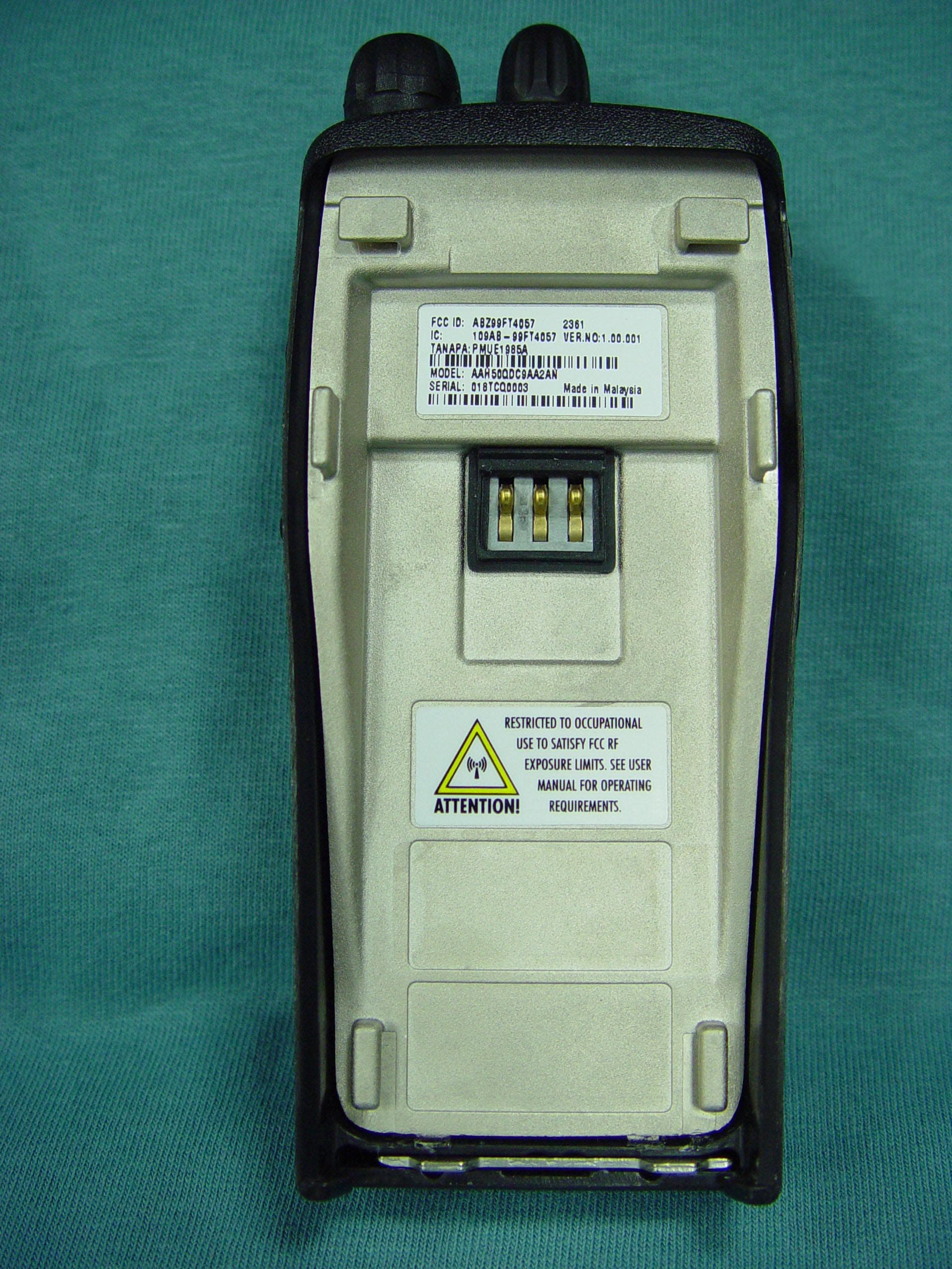
Click to zoom
Application Details
- Equipment Class
- TNF - Licensed Non-Broadcast Transmitter Held to Face
- Date of Grant
- Aug 21, 2003
- Application Purpose
- Original Equipment
- Date of Application
- Aug 21, 2003
- Equipment Note
- CP200 UHF Portable Radio
- Frequency Range
- 403.00000000 - 440.00000000
- Company
- Motorola Solutions, Inc.
- Country
- United States
Documents & Files
Document Text
Text extracted from the exhibit documents filed with the FCC. Open a document above to read the original.
Users Manual
MOTOROLA, the Stylized M Logo, and Radius are registered in the US Patent & Trademark Office.All other product or service names are the property of their respective owners. © Motorola, Inc. 2002. All rights reserved. Printed in U.S.A.MOTOROLA, le logotype au M stylisé et Radius sont enregistrés auprès du Bureau des marques et brevets des États-Unis.Tous les autres noms de produits et de services sont la propriété de leurs titulaires respectifs.© Motorola, Inc. 2002. Tous droits réservés. Imprimé aux États-Unis. *6880309N60*6880309N60-O CP150 ™ /CP200 ™ Commercial SeriesTwo-Way Radio User GuideManuel de l'utilisateurde la radio bidirectionnelle 309N60-O_cvr.qxd 1/9/2003 11:12 AM Page 1 1 English CONTENTS CONTENTS Computer Software Copyrights . . . . . . . . . . 2Safety and Warranty . . . . . . . . . . . . . . . . . 3Product Safety and RF Exposure Compliance . . . . . . . . . . . . . . . . . . . . . . . . 3 Battery Information . . . . . . . . . . . . . . . . . . . 3 Charging Batteries . . . . . . . . . . . . . . . . . 3 Limited Warranty . . . . . . . . . . . . . . . . . . . . . 4Radio Overview . . . . . . . . . . . . . . . . . . . . . 9Parts of the Radio . . . . . . . . . . . . . . . . . . . . 9 CP150™/CP200™ Models . . . . . . . . . . 9On/Off/Volume Knob . . . . . . . . . . . . . . 10Channel Selector Knob . . . . . . . . . . . . 10Push-to-Talk (PTT) Button . . . . . . . . . . 10Microphone . . . . . . . . . . . . . . . . . . . . . 10LED Indicator . . . . . . . . . . . . . . . . . . . . 10Programmable Buttons . . . . . . . . . . . . 11 Indicator Tones . . . . . . . . . . . . . . . . . . . . . 13Audio Indicators for Programmable Buttons . . . . . . . . . . . . . . . . . . . . . . . . . . 14 Improved Audio Features . . . . . . . . . . . . . 14 Companding. . . . . . . . . . . . . . . . . . . . . 14 Getting Started . . . . . . . . . . . . . . . . . . . . 15Battery Information . . . . . . . . . . . . . . . . . . 15 Charging Your Battery . . . . . . . . . . . . . 15Wall Charger . . . . . . . . . . . . . . . . . . . . 15Desktop Charger . . . . . . . . . . . . . . . . . 16 Accessory Information . . . . . . . . . . . . . . . 17 Attaching the Battery . . . . . . . . . . . . . . 17Removing the Battery . . . . . . . . . . . . . 17Attaching the Antenna . . . . . . . . . . . . . 18Removing the Antenna . . . . . . . . . . . . 18Attaching the Belt Clip . . . . . . . . . . . . . 19Removing the Belt Clip . . . . . . . . . . . . 19 Turning the Radio On or Off . . . . . . . . . . . 20Adjusting the Volume . . . . . . . . . . . . . . . . 20Selecting a Radio Channel . . . . . . . . . . . . 20Sending a Call . . . . . . . . . . . . . . . . . . . . . 21Receiving a Call . . . . . . . . . . . . . . . . . . . . 21Monitoring . . . . . . . . . . . . . . . . . . . . . . . . . 21VOX Operation . . . . . . . . . . . . . . . . . . . . . 22Enable/Disable Headset Sidetone . . . . . . 22 VOX Headset. . . . . . . . . . . . . . . . . . . . 22Non-VOX Headset with In-Line PTT . . 23 Radio Calls . . . . . . . . . . . . . . . . . . . . . . . 25Repeater or Talkaround Mode . . . . . . . . . 25Setting Tight or Normal Squelch. . . . . . . . 25Setting the Power Level . . . . . . . . . . . . . . 25Receiving a Selective Call . . . . . . . . . . . . 26Receiving a Call Alert Page . . . . . . . . . . . 26 Non-displayTOC.fm Page 1 Thursday, December 19, 2002 5:08 PM 2 English CONTENTS Scan . . . . . . . . . . . . . . . . . . . . . . . . . . . . . 27Starting or Stopping Scan. . . . . . . . . . . . . 27Talkback . . . . . . . . . . . . . . . . . . . . . . . . . . 27Deleting a Nuisance Channel . . . . . . . . . . 27 Restoring a Channel to the Scan List . 28 Prioritizing a Scan List Member . . . . . . . . 28Accessories . . . . . . . . . . . . . . . . . . . . . . 29Carry Accessories. . . . . . . . . . . . . . . . . . . 29Chargers . . . . . . . . . . . . . . . . . . . . . . . . . . 29Batteries . . . . . . . . . . . . . . . . . . . . . . . . . . 29Headsets . . . . . . . . . . . . . . . . . . . . . . . . . 29Surveillance Accessories . . . . . . . . . . . . . 30Remote Speaker Microphones . . . . . . . . . 31Antennas . . . . . . . . . . . . . . . . . . . . . . . . . 31 COMPUTER SOFTWARE COPYRIGHTSThe Motorola products described in this manual may include copyrighted Motorola computer programs stored in semiconductor memories or other media. Laws in the United States and other countries preserve for Motorola certain exclusive rights for copyrighted computer programs including, but not limited to, the exclusive right to copy or reproduce in any form the copyrighted computer program. Accordingly, any copyrighted Motorola computer programs contained in the Motorola products described in this manual may not be copied, reproduced, modified, reverse-engineered, or distributed in any manner without the express written permission of Motorola. Furthermore, the purchase of Motorola products shall not be deemed to grant either directly or by implication, estoppel, or otherwise, any license under the copyrights, patents or patent applications of Motorola, except for the normal non-exclusive license to use that arises by operation of law in the sale of a product. Non-displayTOC.fm Page 2 Tu esday, December 17, 2002 2:48 PM 3 English SAFETY AND WARRANTY SAFETY AND WARRANTY PRODUCT SAFETY AND RF EXPOSURE COMPLIANCE ATTENTION! This radio is restricted to occupational use only to satisfy FCC RF energy exposure requirements. Before using this product, read the RF energy awareness information and operating instructions in the Product Safety and RF Exposure booklet enclosed with your radio (Motorola Publication part number 68P81095C98) to ensure compliance with RF energy exposure limits. For a list of Motorola-approved antennas, batteries, and other accessories, visit the following web site which lists approved accessories: http://www.motorola.com/cgiss/index.shtml. BATTERY INFORMATIONCharging BatteriesThis product is powered by a nickel-cadmium (NICd) or lithium-ion (Lilon) r…
Text truncated - open the document above for the full version.
Users Manual
English Product Safety and RF Exposure for Portable Two-Way Radios The information provided in this document supersedes the general safety information contained in user guides published prior to February 2002. For radios that have been approved as intrinsically safe, read the instructions and information on intrinsic safety on page 9 of this booklet. Compliance with RF Energy Exposure Standards NOTICE: This radio is intended for use in occupational/controlled applications where users have been made aware of the potential for exposure and can exercise control over their exposure. This radio device is NOT authorized for general population, consumer or similar use. BEFORE USING THIS RADIO, READ THIS BOOKLET WHICH CONTAINS IMPORTANT OPERATING INSTRUCTIONS FOR SAFE USAGE AND RF ENERGY AWARENESS AND CONTROL INFORMATION FOR COMPLIANCE WITH RF ENERGY EXPOSURE LIMITS IN APPLICABLE NATIONAL AND INTERNATIONAL STANDARDS. ! C a u t i o n © Motorola, Inc. 2003 8000 W. Sunrise Blvd., Ft. Lauderdale, FL 33322 Printed in U.S.A. 3/03. *6881095C98* 68P81095C98-A 2 English Federal Communication Commission (FCC) Regulations The FCC has established limits for safe exposure to radio frequency (RF) emissions from portable two-way radios. The FCC requires manufacturers to demonstrate compliance with RF exposure limits before portable two-way radios can be marketed in the U.S. When two-way radios are approved for occupational/ controlled environment exposure limits, the FCC requires users to be fully aware of, and exercise control over, their exposure. Awareness and control of RF exposure can be accomplished by the use of labels, or by education and training through appropriate means, such as information and instructions in user manuals or safety booklets. Your Motorola two-way radio has an RF exposure information label in the battery compartment. This user safety booklet includes useful information about RF exposure and helpful instructions on how to control your RF exposure. Your Motorola two-way radio is designed and tested to comply with a number of national and international standards and guidelines (listed below) regarding human exposure to RF electromagnetic energy. This radio complies with the IEEE (FCC) and ICNIRP exposure limits for occupational/controlled RF exposure environments at usage factors of up to 50% talk–50% listen. In terms of measuring RF energy for compliance with FCC exposure guidelines, your radio radiates measurable RF energy only while it is transmitting (during talking), not when it is receiving (listening) or in standby mode. NOTE:The approved batteries, supplied with this radio, are rated for a 5-5-90 duty cycle (5% talk–5% listen–90% standby), even though this radio complies with FCC occupational exposure limits at usage factors of up to 50% talk. 3 English Your Motorola two-way radio complies with the following RF energy exposure standards and guidelines: • United States Federal Communications Commission, Code of Federal Regulations; 47CFR part 2 sub-part J • American National Standards Institute (ANSI) / Institute of Electrical and Electronic Engineers (IEEE) C95. 1-1992 • Institute of Electrical and Electronic Engineers (IEEE) C95.1-1999 Edition • International Commission on Non-Ionizing Radiation Protection (ICNIRP) 1998 • Ministry of Health (Canada) Safety Code 6. Limits of Human Exposure to Radiofrequency Electromagnetic Fields in the Frequency Range from 3 kHz to 300 GHz, 1999 • Australian Communications Authority Radiocommunications (Electromagnetic Radiation – Human Exposure) Standard, 2001 • ANATEL, Brasil Regulatory Authority, Resolution 256 (April 11, 2001) “additional requirements for SMR, cellular and PCS product certification.” Compliance and Control Guidelines and Operating Instructions for Portable Two-Way Radios To control your exposure and ensure compliance with the occupational/ controlled environment exposure limits, always adhere to the following procedures: • Transmit no more than 50% of the time. To transmit (talk), push the Push- To-Talk (PTT) button. To receive calls, release the PTT button. Transmitting 50% of the time or less is important since the radio generates measurable RF energy exposure only when transmitting (in terms of measuring standards compliance). 4 English • Hold the radio in a vertical position in front of the face with the microphone (and other parts of the radio including the antenna) at least one to two inches (2.5 to 5 centimeters) away from the lips. Keeping the radio at a proper distance is important since RF exposures decrease with increasing distance from the antenna. •For body-worn operation, always place the radio in a Motorola-approved clip, holder, holster, case, or body harness for this product. All Motorola- approved accessory, antenna, and device combinations comply with FCC occupational/controlled environment RF exposure limits. Exposure information on various accessory, antenna, and device combinations can be found under the “Display Exhibits” section of http://www.fcc.gov/oet/ fccid after searching on the FCC ID number, which can be obtained from the label of your radio. Using non–Motorola-approved accessories may result in exposure levels which exceed the FCC’s occupational/controlled environment RF exposure limits. • If you are not using a body-worn accessory and are not using the radio in the intended use position in front of the face, ensure the antenna and the radio are kept one inch (2.5 centimeters) from the body when transmitting. Keeping the radio at a proper distance is important since RF exposures decrease with increasing distance from the antenna. •Use only Motorola-approved supplied or replacement antennas, batteries, and accessories. Use of non–Motorola-approved antennas, batteries and accessories may exceed FCC RF exposure guidelines. For a list of Motorola- approved antennas, batteries, and other accessories, visit the following web site which lists approved accessories: http://www.motorola.com/cgiss/inde…
Text truncated - open the document above for the full version.
Attestation Statements
MOTOROLA INC FCC ID: ABZ99FT4057 EXHIBIT 2 SHEET 1 OF 1 CERTIFICATION OF DATA Pursuant to 47 CFR 2.1517(g) The technical data supplied with this application, having been taken under my supervision, is hereby duly certified. The following is a statement of my qualifications: 1) I have received a BSEE degree in Electrical Engineering from Northwestern University, Evanston, Illinois. 2) I have 31 years experience in developing, testing and certifying Land Mobile Communications Products. NAME: James M. Zima SIGNATURE: DATE: August 18, 2003 POSITION: Principal Staff Engineer I hereby certify that the above application was prepared under my direction and that to the best of my knowledge and belief, the facts set forth in the application and accompanying technical data are true and correct: NAME: James M. Dodis SIGNATURE: DATE: August 18, 2003 POSITION: Engineering Manager
Cover Letter(s)
EXHIBIT 13A SHEET 1 OF 1 FCC ID: ABZ99FT4057 Date: August 18, 2003 Authorization & Evaluation Division Federal Communications Commission Laboratory 7435 Oakland Mills Road Columbia, MD 21046 Subject: Application for Certification of Transmitter with FCC ID: ABZ99FT4057 Dear Sir or Madam: Motorola Inc., 1313 East Algonquin Road, Schaumburg, Illinois, herein submits application for Certification of the equipment identified by FCC ID number ABZ99FT4057. This transmitter is primarily intended for use in a portable radio application with capabilities for conventional communications with a conducted transmit power which is adjustable from 1 Watt (+30 dBm) to 4.6 Watts (+36.6 dBm). The subject transmitter complies with CFR Title 47, Section 90.203, in that the operator cannot directly program the transmit frequencies using only the normally accessible external controls of the unit. Enclosed is a complete Certification Application. Please contact me if you require any additional information. Sincerely, Donna Tokarz NPR Coordinator Tel: (847) 576-7245 Fax: (847) 538-4312 E-mail: [email protected]
Cover Letter(s)
EXHIBIT 13B SHEET 1 OF 1 FCC ID: ABZ99FT4057 REQUEST FOR CONFIDENTIALITY Date: August 18, 2003 Authorization & Evaluation Division Federal Communications Commission Laboratory 7435 Oakland Mills Road Columbia, MD 21046 Subject: Application for Certification of Transmitter with FCC ID: ABZ99FT4057 Dear Sir or Madam: Motorola is requesting that Exhibit 4 (Circuit Descriptions), Exhibit 5 (Schematic Diagrams), Exhibit 10 (Parts List and Tune Up Procedures), and Exhibit 12 (Operational Description) not be made routinely available for public inspection. Motorola considers the information in these exhibits to be classified as trade secrets, pursuant to 47 CFR Section 0.457(d) and Section 552(b)(4) of the Freedom of Information Act. Please mark Exhibits 4, 5, 10, and 12 as “Confidential.” Please contact me if you require any additional information. Sincerely, Donna Tokarz NPR Coordinator Tel: (847) 576-7245 Fax: (847) 538-4312 E-mail: [email protected]
External Photos
MOTOROLA INC FCC ID: ABZ99FT4057 EXHIBIT 3 SHEET 1 OF 4 FRONT VIEW WITH ANTENNA ATTACHED CP200 MODEL MOTOROLA INC FCC ID: ABZ99FT4057 EXHIBIT 3 SHEET 2 OF 4 REAR VIEW WITH BATTERY AND ANTENNA ATTACHED CP200 MODEL MOTOROLA INC FCC ID: ABZ99FT4057 EXHIBIT 3 SHEET 3 OF 4 REAR VIEW WITH BATTERY REMOVED SHOWING FCC ID LABEL AND RF SAFETY LABEL MOTOROLA INC FCC ID: ABZ99FT4057 EXHIBIT 3 SHEET 4 OF 4 CLOSE-UP VIEW OF FCC ID LABEL
ID Label/Location Info
MOTOROLA INC FCC ID: ABZ99FT4057 EXHIBIT 1 SHEET 1 OF 2 IDENTIFICATION LABEL Pursuant to 47 CFR 2.925(a), 2.1033(c), 2.1065 LOCATION A nameplate of the type presented below will be affixed to every transmitter. It will be placed on the outside of the cast housing at the bottom rear of the unit. Shown below is a photo of the actual label affixed to the cast housing of the transmitter. TYPE The label is a paper polyester film laminate with a pressure sensitive adhesive backing. The adhesive is a permanent type acrylic with a minimum peel strength of 40 oz/inch. MOTOROLA INC FCC ID: ABZ99FT4057 EXHIBIT 1 SHEET 2 OF 2 EXHIBIT 1A - GENERAL INFORMATION 1. Production Plans: Quantity production is planned. 2. Application References: TIA/EIA-603-A Land Mobile FM or PM Communications Equipment Measurement and Performance Standards Code of Federal Regulations Title 47, Part 2, Section 2.1033-2.1093, and Part 90, Sections 90.210 and 90.214 3. Data Submittal Procedure: Data is supplied in accordance with Part 2, Sub-part J of the Commission’s rules. The intended use of this transceiver includes applications covered in the Code of Federal Regulations Title 47, Part 90. Maximum transmitter power shall not be adjustable by the user.
Internal Photos
MOTOROLA INC FCC ID: ABZ99FT4057 EXHIBIT 9 SHEET 1 OF 4 FRONT VIEW WITH CIRCUIT BOARD REMOVED FROM HOUSING (MATING SURFACES OF CIRCUIT BOARD AND HOUSING ARE SHOWN) MOTOROLA INC FCC ID: ABZ99FT4057 EXHIBIT 9 SHEET 2 OF 4 REAR VIEW OF CIRCUIT BOARD REMOVED FROM CHASSIS (MATING SURFACES OF CIRCUIT BOARD AND CHASSIS ARE SHOWN) MOTOROLA INC FCC ID: ABZ99FT4057 EXHIBIT 9 SHEET 3 OF 4 REAR VIEW OF CIRCUIT BOARD WITH ALL SHIELDS REMOVED MOTOROLA INC FCC ID: ABZ99FT4057 EXHIBIT 9 SHEET 4 OF 4 FRONT VIEW OF CIRCUIT BOARD WITH ALL SHIELDS REMOVED
Parts List/Tune Up Info
MOTOROLA INC. FCC ID: ABZ99FT4057 EXHIBIT 10 PARTS LIST AND TUNE UP PROCEDURES (CONFIDENTIALITY REQUESTED) This exhibit contains a list of the semiconductor devices used in the transceiver and the test equipment and tuning procedures for maintaining the transceiver. EXHIBIT 10A Function of RF Semiconductors and Other Active Devices EXHIBIT 10B List of Recommended Test Equipment for Servicing EXHIBIT 10C Tune Up Information MOTOROLA INC. FCC ID: ABZ99FT4057 EXHIBIT 10A SHEET 1 OF 2 Exhibit 10A - Function of RF Semiconductors & Other Active Devices Pursuant to 47 CFR 2.10339(c)(10) REF PART CIRCUIT OPERATING INDUSTRY NO. NUMBER APPLICATION FREQUENCY EQUIVALENT CR1 4813825A19 RF LIMITER 403 - 440 MHz MMBD352 CR41 4802246J04 RX FIRST MIXER 44.85 - 440 MHz HSMS2829 CR51 4813825A19 RF LIMITER 44.85 MHz MMBD352 D51 4802245J97 RF SWITCH 455 kHz DAN235ETL D52 4802245J97 RF SWITCH 455 kHz DAN235ETL D120 4880973Z02 TX ANTENNA SERIES SWITCH 403 - 440 MHz MA4PH261 D121 4809948D12 RX ANTENNA SHUNT SWITCH 403 - 440 MHz MA4PH261 D201 4862824C03 REF OSC FREQ CONTROL 16.8 MHz 1SV232 D220 4802233J09 VOLTAGE MULTIPLIER 1.05 MHz IMN10 D221 4802233J09 VOLTAGE MULTIPLIER 1.05 MHz IMN10 D251 4862824C01 RX VCO FREQ CONTROL 358.15 – 395.15 MHz 1SV229 D261 4862824C01 TX VCO FREQ CONTROL 403 - 440 MHz 1SV229 D262 4862824C01 TX VCO MODULATOR AUDIO - 440 MHz 1SV229 D301 4813833A19 REVERSE POLARITY PROTECT DC MBRM120ET3 D414 4805129M41 BOOT CONTROL DC MMBD501 D424 4809924D18 BATT CHEMISTRY DETECT DC RB520S-30 D440 4805729G49 RED/GRN LED INDICATOR DC BRPY1204W D470 4809924D18 BATT CHARGER DC RB520S-30 D471 4809924D18 BOOT/RESET LOGIC DC RB520S-30 D491 4805129M41 AUDIO AGC CONTROL AUDIO MMBD501 Q21 4802247J01 RF AMPLIFIER 403 - 440 MHz BFS505 Q22 4805723X02 CURRENT MIRROR DC UMT1 Q51 4802197J95 FIRST I-F AMPLIFIER 44.85 MHz PBR941 Q70 4880214G02 RX DETECTOR BUFFER 455 kHz MMBT3904 Q100 4885593U03 TX PRE-DRIVER 403 - 440 MHz BFG540W Q150 4880214G02 CURRENT-VOLTAGE CONVERTER DC MMBT3904 Q170 4809939C34 TX DC SWITCH DC EMB10 Q171 4880048M01 TX DC SWITCH DC DTC144EKA Q280 4802245J95 RX VCO BUFFER AMP 358.15 – 395.15 MHz BFS540 Q311 4809579E18 DC SWITCH DC TP0101T Q312 4809579E18 DC SWITCH DC TP0101T Q313 4802245J54 DC SWITCH DC UMG5 Q402 4880048M01 DC SWITCH DC DTC144EKA Q403 4813824A17 DC SWITCH DC MMBT3906 Q410 4802245J54 DATA SWITCH < 19.2 kHz UMG5 Q440 5180159R01 DC SWITCH DC IMX1 Q470 4805723X02 DC SWITCH DC UMT1 Q471 4802245J54 BOOT/RESET LOGIC DC UMG5 MOTOROLA INC. FCC ID: ABZ99FT4057 EXHIBIT 10A SHEET 2 OF 2 Exhibit 10A - Function of RF Semiconductors & Other Active Devices (cont’d) Q472 4805723X02 BOOT/RESET LOGIC DC UMT1 Q481 4813824A17 AUDIO SWITCH AUDIO MMBT3906 Q482 4813824A10 AUDIO SWITCH AUDIO MMBT3904 Q490 4802245J54 DC/AUDIO SWITCH DC - AUDIO UMG5 Q493 4809579E18 DC SWITCH DC TP0101T Q494 4802245J54 DC SWITCH DC UMG5 Q520 5180159R01 DC SWITCH DC IMX1 U51 5186144B01 RECEIVER SYSTEM AUDIO - 44.85 MHz SA616 U52 5109522E10 DC SWITCH DC TC7W04F U110 0186438Z03 TX RF POWER AMP MODULE 403 - 440 MHz RA07M4047M U150 5113818A01 TRANSMITTER POWER CONTROL DC LM2904 U201 5185963A27 FREQUENCY SYNTHESIZER 1.05 - 440 MHz 63A27 U251 5105750U54 VCO/BUFFER IC 358.15 - 440 MHz 50U54 U310 5102478J01 VOLTAGE REGULATOR DC TK71750S U320 5185963A55 VOLTAGE REGULATOR DC LP2986 U330 5102479J01 VOLTAGE REGULATOR DC TK71730S U401 5102226J56 MICROPROCESSOR 7.4 MHz MC68HC11FL0 U402 5102463J64 EEPROM 1 MHz X25128-2.7 U404 5102480J01 FLASH ROM 1.85 MHz AT49HLV001 U451 5185130C53 AUDIO FILTER AUDIO - 16.8 MHz 30C53 U480 5113818A01 AUDIO AMPLIFIER AUDIO LM2904 U490 5108858K99 AUDIO POWER AMPLIFIER AUDIO TDA8541 U510 5113818A01 AUDIO AMPLIFIER AUDIO LM2904 VR110 4813830A86 ESD PROTECTION DC MM3Z3V9T1 VR301 4813830A33 ESD PROTECTION DC MMBZ5250B VR302 4813830A33 ESD PROTECTION DC MMBZ5250B VR471 4813830A18 DC LEVEL DETECTOR DC MMBZ5235B VR472 4813830A09 DC LEVEL DETECTOR DC MMBZ5226B VR473 4813830A33 ESD PROTECTION DC MMBZ5250B VR474 4813830A33 ESD PROTECTION DC MMBZ5250B VR475 4880140L20 ESD PROTECTION DC MMBZ5245B MOTOROLA INC. FCC ID: ABZ99FT4057 EXHIBIT 10B SHEET 1 OF 1 Exhibit 10B - List of Recommended Test Equipment for Servicing Instrument Recommended Type Application RF Signal Generator * HP 8656B or equivalent Receiver Measurements Modulation Analyzer * HP 8901B or equivalent Frequency and Deviation Measurements Audio Analyzer * HP 8903A or equivalent Receiver Measurements Power Meter * HP 438A or equivalent Transmitter Power Output Power Sensor * HP 8482A or equivalent Transmitter Power Output DC Power Supply 0-20 volts at 15 amps Attenuator Pad * 50 Ω, 75 Watts, 30 dB Transmitter Measurements DC Ammeter 30 mA to 20 A Current Drain Measurements Computer IBM PC, PC/XT or PC/AT Radio Alignment Radio Interface Box RLN4008E Computer Interface to Radio Cable 3080369B72 From RIB to Computer Cable AAPMKN4004 From RIB to Radio Software RVN4191 Radio Alignment * These items can be replaced by a Motorola 2000 Series Communications System Analyzer or equivalent piece of integrated communications test equipment. MOTOROLA INC. FCC ID: ABZ99FT4057 EXHIBIT 10C SHEET 1 OF 6 Exhibit 10C - Tune Up Information Pursuant to 47 CFR 2.10339(c)(9) All transmitter adjustments are performed by electronic means. The transmitter contains no electromechanical components for the purpose of transmitter tuning or adjustment. The tuning elements that are used for transmitter adjustment are: Location Type of Element Function U401 Microprocessor Supplies data to Audio Filter IC, Fractional-N Synthesizer, Temperature Compensated Crystal Oscillator, and Power Control IC for Transmitter Modulation, Frequency and Power Adjustment U201 Programmable Attenuator Reference Modulation Balance U451 Programmable Attenuator Deviation Adjustment U201 Digital to Analog Converter Transmitter Frequency Adjustment U451 Digital to Analog Converter Transmitter Power Adjustment The value of a particular tuning element is determined by data sent to that tuning element by microprocessor U40…
Text truncated - open the document above for the full version.
RF Exposure Info
Form-SAR-Rpt-Rev. 2.00 Page 1 of 22 CGISS EME Test Laboratory 8000 West Sunrise Blvd Fort Lauderdale, FL. 33322 S.A.R. EME Compliance Test Report Part 1 of 2 Note: Based on the information and the testing results provided herein, the undersigned certifies that when used as stated in the operating instructions supplied, said product complies with the national and international reference standards and guidelines listed in section 2.0 of this report. Signature on file 8/8/2003 ____________________________________________________________ _________________________ Ken Enger Date Approved Senior Resource Manager, Laboratory Director, CGISS EME Lab Note: This report shall not be reproduced without written approval from an officially designated representative of the Motorola EME Laboratory. n Attention: FCC Date of Report: August 8, 2003 Report Revision: Rev. A Manufacturer: Motorola Product Description: Portable 403-440 MHz 1-4W 16 Channel FCC ID: ABZ99FT4057 Device Model: AAH50QDC9AA2AN Certificate Number: 1449-02 Test Period: 5/16/03-7/29/03 EME Tech: Ed Church EME Engineer: Deanna Zakharia Elect. Principle Staff Engineer Author: Michael Sailsman Global EME Regulatory Affairs Liaison and Deanna Zakharia Elect. Principle Staff Engineer Form-SAR-Rpt-Rev. 2.00 Page 2 of 22 TABLE OF CONTENTS Part 1 of 2 1.0 Introduction 2.0 Reference Standards and Guidelines 3.0 Description of Test Sample 3.1 Test Signal 3.2 Test Output Power 4.0 Description of Test Equipment 4.1 Description of S.A.R Measurement System 4.2 Description of Phantom 4.2.1 Flat Phantom 4.2.2 SAM phantom 4.3 Simulated Tissue Properties 4.3.1 Type of Simulated Tissue 4.3.2 Simulated Tissue Composition 4.4 Test condition 5.0 Description of Test Procedure 5.1 Device Test Positions 5.1.1 Abdomen 5.1.2 Head 5.1.3 Face 5.2 Test Position Photographs 5.3 Probe Scan Procedures 6.0 Measurement Uncertainty 7.0 S.A.R. Test Results 7.1 S.A.R. results 7.2 Peak S.A.R. location 7.3 Highest S.A.R. results calculation methodology 8.0 Conclusion Part 2 of 2 Appendix A: Power Slump Data/Shortened scan Appendix B: Data Results Appendix C: Dipole System Performance Check Results Appendix D: Calibration Certificates Appendix E: Illustration of Body-worn Accessories Appendix F: Accessories and options test status and separation distances Form-SAR-Rpt-Rev. 2.00 Page 3 of 22 REVISION HISTORY Date Revision Comments 7/22/03 O Initial release Prototype results 8/8/03 A Expanded frequency range from 403-438 MHz to 403-440 MHz; replaced the optional antenna with a new one; updated data and scans to reflect the changes. Form-SAR-Rpt-Rev. 2.00 Page 4 of 22 1.0 Introduction This report details the utilization, test setup, test equipment, and updated test results of the Specific Absorption Rate (S.A.R.) measurements performed at the CGISS EME Test Lab for model number AAH50QDC9AA2AN, FCC ID: ABZ99FT4057. The applicable exposure environment is Occupational/Controlled. The test results included herein represent the highest S.A.R. levels applicable to this product and clearly demonstrate compliance with FCC Occupational/Controlled RF Exposure limit of 8.0 mW/g per the requirements of 47 CFR 2.1093(d). 2.0 Reference Standards and Guidelines This product is designed to comply with the following national and international standards and guidelines. • United States Federal Communications Commission, Code of Federal Regulations; 47CFR part 2 sub-part J • American National Standards Institute (ANSI) / Institute of Electrical and Electronic Engineers (IEEE) C95. 1-1992 • Institute of Electrical and Electronic Engineers (IEEE) C95.1-1999 Edition • International Commission on Non-Ionizing Radiation Protection (ICNIRP) 1998 • Ministry of Health (Canada) Safety Code 6. Limits of Human Exposure to Terminal frequency Electromagnetic Fields in the Frequency Range from 3 kHz to 300 GHz, 1999 • Australian Communications Authority Terminal communications (Electromagnetic Radiation - Human Exposure) Standard 2003 • ANATEL, Brazil Regulatory Authority, Resolution 256 (April 11, 2001) "additional requirements for SMR, cellular and PCS product certification." Form-SAR-Rpt-Rev. 2.00 Page 5 of 22 3.0 Description of Test Sample The portable handheld transceiver, FCC ID: ABZ99FT4057, operates using frequency modulation (FM) and incorporates traditional simplex two-way radio transmission protocol. The intended operating positions are “at the face” with the microphone 1 to 2 inches from the mouth, and “at the abdomen” by means of the offered body-worn accessories. Audio and PTT operation while the radio is at the abdomen is accomplished by means of optional remote accessories that connect to the radio. This device will be marketed to and used by employees solely for work-related operations, such as public safety agencies, e.g. police, fire and emergency medical. User training is the responsibility of these agencies, who can be expected to employ the usage instructions, safety information and operational cautions set forth in the user's manual, instructional sessions or other means. Motorola also makes available to its customers training classes on the proper use of two-way radios and wireless data devices. FCC ID: ABZ99FT4057 is capable of operating in the 403-440 MHz band. The rated power is 1-4 watts with a maximum output capability of 4.6 watts as defined by the upper limit of the production line final test station. Form-SAR-Rpt-Rev. 2.00 Page 6 of 22 FCC ID: ABZ99FT4057 is offered with the following options and accessories: Antenna NAE6483AR Whip 403-520 MHz ¼ wave; -0.0 dBi NAE6522AR Heliflex 438-470 MHz ¼ wave; -2.0 dBi Batteries NNTN4497AR Lithium Ion Battery 1800 mAh NNTN4496AR NiCd Battery 1100 mAh Body-worn Accessories HLN6602A Universal Chest Pack 1505596Z02 Replacement Strap for HLN6602 Universal Chest Pack RLN4570A Break-A-Way Chest Pack RLN4815A Universal Radio Pak 4280384F89 Replacement Belt Lengthener for RLN4815 HLN9985B Waterproof Bag NTN5243A Shoulder Carry Strap, attaches to D-Sha…
Text truncated - open the document above for the full version.
RF Exposure Info
Form-SAR-Rpt-Rev. 2.00 Page 1 of 51 CGISS EME Test Laboratory 8000 West Sunrise Blvd Fort Lauderdale, FL. 33322 S.A.R. EME Compliance Test Report Part 2 of 2 Note: Based on the information and the testing results provided herein, the undersigned certifies that when used as stated in the operating instructions supplied, said product complies with the national and international reference standards and guidelines listed in section 2.0 of this report. Signature on file 8/8/2003 ____________________________________________________________ _________________________ Ken Enger Date Approved Senior Resource Manager, Laboratory Director, CGISS EME Lab Note: This report shall not be reproduced without written approval from an officially designated representative of the Motorola EME Laboratory. Attention: FCC Date of Report: August 8, 2003 Report Rev…
Text truncated - open the document above for the full version.
Contact Information
Applicant
Matthew Nawrocki
Technical Contact
Motorola Inc.James M Zima
[email protected]847-576-3697
1313 East Algonquin Road · Schaumburg, Illinois · United States
Test Firm
Motorola, Inc.William Bily
847-576-2238Fax: 847-538-3905
Technical Specifications
| # | Rule Parts | Frequency Range | Power Output | Emission | Tolerance |
|---|---|---|---|---|---|
| 2 | 22,74,90,90.21 | 403 MHz - 440 MHz | 4.6 W | 16K0F3E | 2.5 ppm |
Other Applications from Motorola Solutions, Inc.

ABZ89FT4940
Aug 06, 2026Non Broadcast Transmitter
Equipment Class
TNB - Licensed Non-Broadcast Station TransmitterABZ89FT4950
Jun 25, 2026Non-Broadcast Transmitter
Equipment Class
TNB - Licensed Non-Broadcast Station TransmitterABZ89FT5901
Jun 20, 2024Non Broadcast Transmitter
Equipment Class
TNB - Licensed Non-Broadcast Station Transmitter
ABZ99FT5101B
May 02, 2023Non Broadcast Transmitter
Equipment Class
PCB - PCS Licensed Transmitter
ABZ99FT3095B
Mar 26, 2023Non Broadcast Transmitter
Equipment Class
TNB - Licensed Non-Broadcast Station Transmitter