ABZ99FT4090UHF Portable Radio
Motorola Solutions, Inc.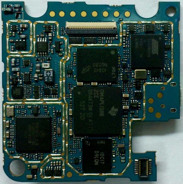
Click to zoom
Application Details
- Equipment Class
- TNF - Licensed Non-Broadcast Transmitter Held to Face
- Date of Grant
- Feb 12, 2012
- Application Purpose
- Original Equipment
- Date of Application
- Feb 05, 2012
- Equipment Note
- UHF Portable Radio
- Frequency Range
- 406.10000000 - 470.00000000
- Company
- Motorola Solutions, Inc.
- Country
- United States
Documents & Files
Document Text
Text extracted from the exhibit documents filed with the FCC. Open a document above to read the original.
Users Manual
PROFESSIONAL DIGITAL TWO-WAY RADIO MOTOTRBO™ SL755 0 PORTABLE USER GUIDE Declaration of Conformity English i Declaration of Conformity This declaration is applicable to your radio only if your radio is labeled with the FCC logo shown below. DECLARATION OF CONFORMITYPer FCC CFR 47 Part 2 Section 2.1077(a)Responsible Party Name: Motorola Solutions, Inc.Address: 1303 East Algonquin Road, Schaumburg, IL 60196, U.S.A.Phone Number: 1-800-927-2744Hereby declares that the product: Model Name: SL 7550 conforms to the following regulations: FCC Part 15, subpart B, section 15.107(a), 15.107(d) and section 15.109(a) Class B Digital DeviceAs a personal computer peripheral, this device complies with Part 15 of the FC C Rules. Operation is subject to the following two conditions: 1. This device may not cause harmful interference, and 2. This device must accept any interference received, including interference that may cause undesired operation. NAG-LACR.book Page i Tuesday, January 10, 2012 10:33 AM Declaration of Conformity English ii Note: This equipment has been tested and found to comply with the li mits for a Class B digital device, pursuant to part 15 of the FCC Rules. These limits are designed to provi de reasonable protection against harmful interference in a residential installation. This equipment generates, us es and can radiate radio frequency energy and, if not installed and used in accordance with the instructions, may cause harmful interference to radio communications. However, there is no guarantee that interference wi ll not occur in a particular installation. If this equipment does cause harmful interference to radi o or television reception, which can be determined by turning the equipment off and on, the user is encouraged to try to correct the interference by one or more of the following measures: • Reorient or relocate the receiving antenna. • Increase the separation between the equipment and receiver. • Connect the equipment into an outlet on a circuit differ ent from that to which the receiver is connected. • Consult the dealer or an experienc ed radio/TV technician for help. NAG-LACR.book Page ii Tuesday, January 10, 2012 10:33 AM Contents English i ContentsThis User Guide contains all the information you need to use the MOTOTRBO SL7550 Portable Radios. Important Safety Information . . . . . . . . . . . . . . . . . vi Product Safety and RF Exposure Compliance . . .vi Firmware Version . . . . . . . . . . . . . . . . . . . . . . . . . . . viComputer Software Copyrights . . . . . . . . . . . . . . . vii Open Source Software Legal Notices . . . . . . . . . vii Handling Precautions . . . . . . . . . . . . . . . . . . . . . . viiiRF Energy Exposure and Product Safety Guidelines and Instructions . . . . . . . . . . . . . . . . . . . . . . . . . . . viiiOperating Precautions . . . . . . . . . . . . . . . . . . . . . . . ixGetting Started . . . . . . . . . . . . . . . . . . . . . . . . . . . . . . 1 How to Use This Guide . . . . . . . . . . . . . . . . . . . . . . . 1What Your Dealer/System Administrator Can Tell You . . . . . . . . . . . . . . . . . . . . . . . . . . . . . . 1 Preparing Your Radio for Use . . . . . . . . . . . . . . . . . . 2 Attaching the Battery . . . . . . . . . . . . . . . . . . . . . . . . . 2Charging the Battery . . . . . . . . . . . . . . . . . . . . . . . . . 3 Attaching the Earpiece/Audio Accessory . . . . . . . . . 4 Powering Up the Radio . . . . . . . . . . . . . . . . . . . . . . . 4 Adjusting the Volume . . . . . . . . . . . . . . . . . . . . . . . . 5 Identifying Radio Controls . . . . . . . . . . . . . . . . . . . . 6 Radio Controls . . . . . . . . . . . . . . . . . . . . . . . . . . . . . 6Programmable Buttons . . . . . . . . . . . . . . . . . . . . . . . 7 Assignable Radio Functions . . . . . . . . . . . . . . . . . 8Assignable Settings or Utility Functions . . . . . . . . . 9 Using the 4-Way Navigation Disc . . . . . . . . . . . . . . . 9 Accessing the Programmed Functions . . . . . . . . . 10Using the Keypad . . . . . . . . . . . . . . . . . . . . . . . . . . 11Push-To-Talk (PTT) Bu tton . . . . . . . . . . . . . . . . . . . 12 Capacity Plus . . . . . . . . . . . . . . . . . . . . . . . . . . . . . 13 Identifying Status Indicators . . . . . . . . . . . . . . . . . . 14 Display Icons . . . . . . . . . . . . . . . . . . . . . . . . . . . . . . 14Call Icons . . . . . . . . . . . . . . . . . . . . . . . . . . . . . . . . 16Utilities Icons . . . . . . . . . . . . . . . . . . . . . . . . . . . . . . 16Mini Notice Icons . . . . . . . . . . . . . . . . . . . . . . . . . . . 17Sent Item Icons . . . . . . . . . . . . . . . . . . . . . . . . . . . . 17Job Tickets Icons . . . . . . . . . . . . . . . . . . . . . . . . . . 18LED Indicator . . . . . . . . . . . . . . . . . . . . . . . . . . . . . 18Audio Tones . . . . . . . . . . . . . . . . . . . . . . . . . . . . . . 19Indicator Tones . . . . . . . . . . . . . . . . . . . . . . . . . . . . 20 Making and Receiving Calls . . . . . . . . . . . . . . . . . . 21 Selecting a Zone . . . . . . . . . . . . . . . . . . . . . . . . . . . 21Selecting a Channel . . . . . . . . . . . . . . . . . . . . . . . . 22 NAG-LACR.book Page i Tuesday, January 10, 2012 10:33 AM Contents English ii Receiving and Responding to a Radio Call . . . . . . 23 Receiving and Responding to a Group Call . . . . 23 Receiving and Responding to a Private Call . . . . 24Receiving an All Call . . . . . . . . . . . . . . . . . . . . . . 24 Making a Radio Call . . . . . . . . . . . . . . . . . . . . . . . . 25 Making a Group Call with the PTT Button . . . . 26Making a Private Call with the PTT Button . . . 26Making an All Call . . . . . . . . . . . . . . . . . . . . . . 27 Making a Group or Private Call with the One Touch Access Button . . . . . . . . . . . . . . . . . . . . . . . . . . . 28Making a Group, Private or All Call with the Programmable Number Key . . . . . . . . . . . . . . . . 28 Stopping a Radio Call . . . . . . . . . . . . . . . . . . . . .…
Text truncated - open the document above for the full version.
Users Manual
Identifying Status Indicators English 15 EmergencyRadio is in Emergency mode.Job Ticket NotificationNotification List has items to review.Scan * Scan feature is enabled. Scan – Priority 1 * Radio detects activity on channel/group designated as Priority 1.Scan – Priority 2 * Radio detects activity on channel/group designated as Priority 2.MonitorSelected channel is being monitored.Talkaround * In the absence of a repeater, radio is currently configured for direct radio to radio communication.Site Roaming * The site roaming feature is enabled.Secure The Privacy feature is enabled.Unsecure The Privacy feature is disabled. Option BoardThe Option Board is enabled. (Option board enabled models only).Option Board Non-FunctionThe Option Board is disabled.All Tones Disabled No ring tones available.Call LogRadio call log.ContactRadio contact is availableMessageIncoming message.Silent Ring Silent ring mode is enabled.Ring onlyRinging mode is enabled.Vibrate Vibrate mode is enabled.Vibrate and RingVibrate and ring modes are enabled.Keypad Keypad locked. * Not applicable in Capacity Plus NAG-LACR.book Page 15 Tuesday, January 10, 2012 10:33 AM Identifying Status Indicators English 16 Call Icons The following icons appear on the radio’s display during a call. These icons also appear in the Contacts list to indicate ID type. Utilities Icons The following icons appear beside menu items on the radio’s display that offer the following options. Private CallIndicates a Private Call in progress. Group Call/All CallIndicates a Group Call or All Call in progress. Private Call Alert IconIn the Contacts list, it i ndicates a subscriber alias (name) or ID (number). Checkbox (Empty)Indicates the option is not selected.Checkbox (Checked)Indicates the option is selected.BrightnessIndicates the brightness level.Brightness HighlightedHighlights the brightness level. NAG-LACR.book Page 16 Tuesday, January 10, 2012 10:33 AM Identifying Status Indicators English 17 Mini Notice Icons The following icons appear momentarily on the radio’s display after an action to perform task is taken. Sent Item Icons The following icons appear in the Sent Items folder. Successful Transmission (Positive)Successful action taken.Failed Transmission (Negative)Failed action taken.Transmission in Progress (Transitional)Transmitting. This is seen before indication for Successful Transmission or Failed Transmission. Sent SuccessfullyThe text message is sent successfully.Individual or Group Message Read.The text message has been read.Individual or Group Message Unread.The text message has been unread.Send FailedThe text message cannot be sent. OROR OR OR NAG-LACR.book Page 17 Tuesday, January 10, 2012 10:33 AM Identifying Status Indicators English 18 Job Tickets Icons LED Indicator The LED indicator shows the operational status of your radio.Blinking red – Radio is transmitting at low battery condition, receiving an emergency transmission or has failed the self-test upon powering up.Solid yellow – Radio is monitoring a digital conventional channel. Also indicates fair battery charge when programmable button is pressed.Blinking yellow – Radio is scanning for activity or receiving a Call Alert.Double blinking yellow – Radio is no longer connected to the repeater while in Capacity Plus, all Capacity Plus channels are currently busy, Auto Roaming is enabled, radio is actively searching for a new site, or radio has yet to respond to a group In-Progress • The text message to a group alias or ID is pending transmission. • The text message to a subscriber alias or ID is pending transmission, fo llowed by waiting for acknowledgement. All Jobs Indicates all jobs listed.New JobsIndicates new jobs. OR LED Indicator NAG-LACR.book Page 18 Tuesday, January 10, 2012 10:33 AM Identifying Status Indicators English 19 call alert. Also indicates that radio has yet to respond to a group call alert, or radio is locked.Solid green – Radio is powering up or transmitting. Also indicates full charge of the bat tery when programmable button is pressed.Blinking green – Radio is powering up, receiving a non- privacy-enabled call or data, or detecting activity over the air.Double blinking green – Radio is receiving a privacy-enabled call or data. NOTE: While in conventional mode, when the LED blinks green, it indicates the radio de tects activity over the air. Due to the nature of the digital protocol, this activity may or may not affect the radio's programmed channel. For Capacity Plus, there is no LED indication when the radio is detecting activity over the air. Audio Tones Alert tones provide you with audible indications of the radio’s status or the radio’s response to data received. Continuous Tone A monotone sound. Sounds continuously until termination. Periodic Tone Sounds periodically depending on the duration set by the radio. Tone starts, stops, and repeats itself. Repetitive Tone A single tone that repeats itself until it is terminated by the user. Momentary Tone Sounds only once for a short period of time defined by the radio. NAG-LACR.book Page 19 Tuesday, January 10, 2012 10:33 AM Identifying Status Indicators English 20 Indicator Tones High pitched tone Low pitched tone Positive Indicator ToneNegative Indicator Tone NAG-LACR.book Page 20 Tuesday, January 10, 2012 10:33 AM Making and Receiving Calls English 21 Making and Receiving CallsOnce you understand how your MOTOTRBO SL7550 is configured, you are ready to use your radio.Use this navigation guide to familiarize yourself with the basic Call features:Selecting a Zone . . . . . . . . . . . . . . . . . . . . . . . . . . . . . page 21Selecting a Channel . . . . . . . . . . . . . . . . . . . . . . . . . . page 23Receiving and Responding to a Radio Call . . . . . . . . . page 23Making a Radio Call . . . . . . . . . . . . . . . . . . . . . . . . . . page 25Stopping a Radio Call . . . . . . . . . . . . . . . . . . . . . . . . . page 30Talkaround . . . . . . . . . . . . . . . . . . . . . . . . . . . . . . . . . . page…
Text truncated - open the document above for the full version.
Cover Letter(s)
Date: January 04, 2012 Authorization & Evaluation Division Federal Communications Commission Laboratory 7435 Oakland Mills Road Columbia, MD 21046 Subject: Letter of Authorization for FCC ID ABZ99FT4090 Dear Sir or Madam: This letter is to authorize Larry D. Larsen to sign Form 731 applications on my behalf for the subject FCC ID Filing. Please contact me if there are any questions or issues. Sincerely, Ken Weiss Senior Staff Engineer Tel: (847)-576-2789 Fax: (847)-538-3905 E-mail: [email protected]
ID Label/Location Info
Applicant: Motorola Solutions Inc FCC ID: ABZ99FT4090 EXHIBIT 1 SHEET 1 OF 1 Identification Label LOCATION See the Attached Photograph or Sketch Top of Radio X Back of Radio under Belt Clip Back of Radio TYPE X sensitive adhesive backing. The adhesive is a permanent type acrylic The label is a polyester film laminate with a pressure with the minimum peel strength of 32 oz/inch. MARKINGS (TEXT) X Label Attached Below. See the Attached Photograph and Exhibit 3-5 for the actual location of the FCC label on the device. See Attached Drawing. FIGURE 1-1: FCC L ABEL FOR SALES MODEL AAH81QCN9NA2AN
Internal Photos
Applicant: Motorola Solutions Inc. FCC ID: ABZ99FT4090 EXHIBIT 9 SHEET 1 OF 6 Internal Photographs The following photographs are attached. Exhibit 1. RF board with Shields (Top). 9A 2. RF board without Shields (Top). 9B 3. RF board with Shields (Bottom). 9C 4. RF board without Shields (Bottom). 9D 5. Interface board with Shields (Top). 9E 6. Interface board without Shields (Top). 9F 7. Interface board (Bottom) 9G 8. Housing (Front) 9H 9. PCB board with housing (Back) 9I Applicant: Motorola Solutions Inc. FCC ID: ABZ99FT4090 EXHIBIT 9 SHEET 2 OF 6 Exhibits 9A RF board with Shields (Top) Exhibit 9B RF board without Shields (Top) Applicant: Motorola Solutions Inc. FCC ID: ABZ99FT4090 EXHIBIT 9 SHEET 3 OF 6 Exhibit 9C RF board with Shields (Bottom) Exhibit 9D RF board without Shields (Bottom) Applicant: Motorola Solutions Inc. FCC ID: ABZ99FT4090 EXHIBIT 9 SHEET 4 OF 6 Exhibit 9E Interface board with Shields (Top) Exhibit 9F Interface board without shields (Top) Applicant: Motorola Solutions Inc. FCC ID: ABZ99FT4090 EXHIBIT 9 SHEET 5 OF 6 Exhibit 9G Interface board (Bottom) Exhibit 9H Housing (Front) Applicant: Motorola Solutions Inc. FCC ID: ABZ99FT4090 EXHIBIT 9 SHEET 6 OF 6 Exhibit 9I PCB board with housing (Back)
RF Exposure Info
SR9554 Motorola Solutions EME Form-SAR-Rpt-Rev. 11.0 Page 1 of 46 TESTING CERT # 2518.05 DECLARATION OF COMPLIANCE SAR ASSESSMENT Part 1 of 2 Enterprise Mobility Solutions EME Test Laboratory Motorola Solutions Malaysia Sdn Bhd (455657-H) Customer Solution Center Plot 2, Bayan Lepas Technoplex Industrial Park, Mukim 12 SWD 11900 Bayan Lepas Penang, Malaysia. Date of Report: 10/14/2011 Report Revision: O Report ID: SAR rpt_PMUE3877A_Rev.O _111014_SR9554 Responsible Engineer: CheeChin Tan/ PeiLoo Tey (EME Section Manager) Report Author: CheeChin Tan/ PeiLoo Tey (EME Section Manager) Date/s Tested: 8/22/2011 – 9/30/2011 Manufacturer/Location: Motorola, Penang Sector/Group/Div.: EMS Date submitted for test: 8/09/2011 DUT Description: 403-470 MHz 2W, 2.402-2.480 GHz (Bluetooth), GOB Test TX mode(s): CW (PTT) for UHF; CW (77% duty cycle for Bluetooth) Max. Power output: 2.4 W for UHF; 4 mW for Bluetooth Nominal Power: 2.0 W for UHF; 2.5 mW for Bluetooth Tx Frequency Bands: 403-470 MHz, 2402-2480 MHz Signaling type: TDMA (UHF); FHSS (Bluetooth) Model(s) Tested: PMUE3877A Model(s) Certified: PMUE3877A Serial Number(s): DFLTMN03SL, DFLTMN03S6, DFLTMN03SN Classification: Occupational/Controlled FCC ID: ABZ99FT4090; Rule part 90 (406.1 - 470 MHz); Rule part 15 (2402-2480 MHz) IC: 109AB-99FT4090; (406.1-430 MHz and 450-470 MHz) * Refer to section 15 of part 1 for highest SAR summary results. The test results clearly demonstrate compliance with FCC Occupational/Controlled RF Exposure limits of 8 W/kg averaged over 1 gram per the requirements of 47 CFR 2.1093(d). The 10 grams result is not applicable to FCC filing. The test results clearly demonstrate compliance with ICNIRP (1998) Guidelines for limiting exposure in time-varying electric, magnetic, and electromagnetic fields (up to 300 GHz), Health Physics 74, 494-522 RF Exposure limits of 10 W/kg averaged over 10grams of contiguous tissue. Based on the information and the testing results provided herein, the undersigned certifies that when used as stated in the operating instructions supplied, said product complies with the national and international reference standards and guidelines listed in section 3.0 of this report. This report shall not be reproduced without written approval from an officially designated representative of the Motorola Solutions Inc, Laboratory. I attest to the accuracy of the data and assume full responsibility for the completeness of these measurements. This reporting format is consistent with the suggested guidelines of the TIA TSB-150 December 2004. The results and statements contained in this report pertain only to the device(s) evaluated. Deanna Zakharia EMS EME Lab Senior Resource Manager, Laboratory Director Approval Date: 10/17/2011 Certification Date: 10/17/2011 Certification No.: L1110918 SR9554 Motorola Solutions EME Form-SAR-Rpt-Rev. 11.0 Page 2 of 46 Part 1 of 2 1.0 Introduction ..............................................................................................................4 2.0 Abbreviations / Definitions ......................................................................................4 3.0 Referenced Standards and Guidelines ......................................................................4 4.0 SAR Limits ..............................................................................................................5 5.0 SAR Result Scaling Methodology ...........................................................................6 6.0 Description of Device Under Test (DUT) ................................................................6 7.0 Optional Accessories and Test Criteria ....................................................................7 7.1 Batteries .......................................................................................................7 7.2 Antennas ......................................................................................................7 7.3 Body worn Accessories ............................................................8 7.4 Audio Accessories ..................................................................8 8.0 Description of Test System ......................................................................................8 8.1 Descriptions of Robotics/Probes/Readout Electronics ................................9 8.2 Description of Phantom(s) ...........................................................................9 8.2.1 Dual Flat Phantom ...........................................................................9 8.2.2 SAM Phantom ..................................................................................9 8.2.3 Elliptical Flat Phantom ....................................................................9 8.3 Description of Simulated Tissue ................................................................10 9.0 Additional Test Equipment ....................................................................................11 10.0 SAR Measurement System Verification ................................................................12 10.1 Equivalent Tissue Test Results ..................................................................12 10.2 System Check Test Results ........................................................................13 11.0 Environmental Test Conditions .............................................................................14 12.0 DUT Test Methodology .........................................................................................14 12.1 Measurements ............................................................................................14 12.2 DUT Configuration(s) ................................................................................14 12.3 DUT Positioning Procedures ....................................................................14 12.3.1 Body ............................................................................................14 12.3.2 Head .........................................…
Text truncated - open the document above for the full version.
RF Exposure Info
SR9554 Motorola Solutions EME Form-SAR-Rpt-Rev. 11.0 Page 1 of 24 TESTING CERT # 2518.05 DECLARATION OF COMPLIANCE SAR ASSESSMENT Part 2 of 2 Enterprise Mobility Solutions EME Test Laboratory Motorola Solutions Malaysia Sdn Bhd (455657-H) Customer Solution Center Plot 2, Bayan Lepas Technoplex Industrial Park, Mukim 12 SWD 11900 Bayan Lepas Penang, Malaysia. Date of Report: 10/14/2011 Report Revision: O Report ID: SAR rpt_PMUE3877A_Rev.O _111014_SR9554 Responsible Engineer: CheeChin Tan/ PeiLoo Tey (EME Section Manager) Report Author: CheeChin Tan/ PeiLoo Tey (EME Section Manager) Date/s Tested: 8/22/2011 – 9/30/2011 Manufacturer/Location: Motorola, Penang Sector/Group/Div.: EMS Date submitted for test: 8/09/2011 DUT Description: 403-470 MHz 2W, 2.402-2.480 GHz (Bluetooth), GOB Test TX mode(s): CW (PTT) for UHF; CW (77% duty cycle for Bluetooth) Max. Power output: 2.4 W for UHF; 4 mW for Bluetooth Nominal Power: 2.0 W for UHF; 2.5 mW for Bluetooth Tx Frequency Bands: 403-470 MHz, 2402-2480 MHz Signaling type: TDMA (UHF); FHSS (Bluetooth) Model(s) Tested: PMUE3877A Model(s) Certified: PMUE3877A Serial Number(s): DFLTMN03SL, DFLTMN03S6, DFLTMN03SN Classification: Occupational/Controlled FCC ID: ABZ99FT4090; Rule part 90 (406.1 - 470 MHz); Rule part 15 (2402-2480 MHz) IC: 109AB-99FT4090; (406.1-430 MHz and 450-470 MHz) * Refer to section 15 of part 1 for highest SAR summary results. The test results clearly demonstrate compliance with FCC Occupational/Controlled RF Exposure limits of 8 W/kg averaged over 1 gram per the requirements of 47 CFR 2.1093(d). The 10 grams result is not applicable to FCC filing. The test results clearly demonstrate compliance with ICNIRP (1998) Guidelines for limiting exposure in time-varying electric, magnetic, and electromagnetic fields (up to 300 GHz), Health Physics 74, 494-522 RF Exposure limits of 10 W/kg averaged over 10grams of contiguous tissue. Based on the information and the testing results provided herein, the undersigned certifies that when used as stated in the operating instructions supplied, said product complies with the national and international reference standards and guidelines listed in section 3.0 of this report. This report shall not be reproduced without written approval from an officially designated representative of the Motorola Solutions Inc, Laboratory. I attest to the accuracy of the data and assume full responsibility for the completeness of these measurements. This reporting format is consistent with the suggested guidelines of the TIA TSB-150 December 2004. The results and statements contained in this report pertain only to the device(s) evaluated. Deanna Zakharia EMS EME Lab Senior Resource Manager, Laboratory Director Approval Date: 10/17/2011 Certification Date: 10/17/2011 Certification No.: L1110918 SR9554 Motorola Solutions EME Form-SAR-Rpt-Rev. 11.0 Page 2 of 24 Appendix D Test System Verification Scans The SAR result indicated on the Manufacture’s Calibrated certificates for dipole D450V3 S/N 1053 was not used due to the following: -- The IEEE 1528-2003 and the FCC OET-65 Supplement C, System Verification section indicated that “The measured 1-g SAR should be within 10% of the expected target values specified for the specific phantom and RF source used in the system verification measurement.” -- SPEAG calibration certificate indicates that the allowed tolerance for this dipole is higher than +/-10% (e.g. 4.79 +/-18.1 % at k=2 for the D450V3 S/N 1053). -- The allowed tolerance for the probe is also higher than +/- 10% (e.g. 13.3 % at k=2 at 450 MHz for the probe being used to assess this product). Due to probe, dipole and system tolerances noted above, the lab averages dipole results across multiple probes to establish a set of averaged targets for each dipole using the following procedure: • The System Validation was conducted per IEEE1528-2003 and IEC62209-2 Edition 1.0 2010-03 standards using the simulated head tissue and multiple probes that are available and applicable for the dipole under test to verify the System Validation. Results for this dipole are within the measurement system uncertainty of the reference SAR values indicated within IEC62209-2 Edition 1.0 2010-03 when using a flat phantom with 2mm thickness. These results then are averaged and used as the target for the daily system performance check when the simulated head tissue is used. • The dipole targets for the body are set immediately following the same process noted above. Since there is no standard referencing the SAR values for the System Validation using the simulated body tissue, the compliant System Validation results using the simulated head tissue are used to justify the use of the System Validation results using the simulated body tissue due to the same setup except for the simulated tissue type. The targets set in this report were conducted following the above process. Note that the targets set for the tested dipole, when using the simulated head tissue, meets the requirement for the system validation per IEEE1528-2003, IEC62209-2 Edition 1.0 2010-03 standards, and the difference between this result and the result from the manufacture’s dipole calibration certificate is up to 9.15 % for the 450 MHz which are well within the measurement uncertainty of the measurement system at k=2. To assess the isotropic characteristics of the measurement probe, a probe rotation was performed using the "Rotation (1D)" function in the DASY software with a measured isotropy tolerance of +/- 0.5dB. SR9554 Motorola Solutions EME Form-SAR-Rpt-Rev. 11.0 Page 3 of 24 SR9554 Motorola Solutions EME Form-SAR-Rpt-Rev. 11.0 Page 4 of 24 SR9554 Motorola Solutions EME Form-SAR-Rpt-Rev. 11.0 Page 5 of 24 SR9554 Motorola Solutions EME Form-SAR-Rpt-Rev. 11.0 Page 6 of 24 SR9554 Motorola Solutions EME Form-SAR-Rpt-Rev. 11.0 Page 7 of 24 SR9554 Motorola Solutions EME Form-SAR-Rpt-Rev. 11.0 Page 8 of 24 SR9554 Motorola Solutions EME Form-SAR-Rpt-Rev. 11.0 Page 9 of 24 Appendix E FCC…
Text truncated - open the document above for the full version.
Test Report
Applicant: Motorola Solutions Inc. FCC ID: ABZ99FT4090 EXHIBIT 6 SHEET 1 OF 24 EXHIBIT 6 INDEX OF SUBMITTED MEASURED DATA This exhibit contains the measured data for this equipment as follows: EXHIBIT 6A – RF Power Output EXHIBIT 6B – Audio Frequency Response 6B-1: 12.5 KHz Channel Spacing, 403.125 MHz, Transmit Audio Frequency Response 6B-2: 12.5 KHz Channel Spacing, 406.1125 MHz, Transmit Audio Frequency Response 6B-3: 12.5 KHz Channel Spacing, 429.9875 MHz, Transmit Audio Frequency Response 6B-4: 12.5 KHz Channel Spacing, 436.125 MHz, Transmit Audio Frequency Response 6B-5: 12.5 KHz Channel Spacing, 469.9875 MHz, Transmit Audio Frequency Response EXHIBIT 6C – Audio Low Pass Filter Response 6C-1: 12.5 kHz Channel Spacing, 403.125 MHz, Transmit Audio Low Pass Filter Response 6C-2: 12.5 kHz Channel Spacing, 406.1125 MHz, Transmit Audio Low Pass Filter Response 6C-3: 12.5 kHz Channel Spacing, 429.9875 MHz, Transmit Audio Low Pass Filter Response 6C-4: 12.5 kHz Channel Spacing, 436.125 MHz, Transmit Audio Low Pass Filter Response 6C-5: 12.5 kHz Channel Spacing, 469.9875 MHz, Transmit Audio Low Pass Filter Response EXHIBIT 6D – Modulation Limiting 6D-1: 12.5 KHz Channel Spacing, 403.125 MHz 6D-2: 12.5 KHz Channel Spacing, 406.1125 MHz 6D-3: 12.5 KHz Channel Spacing, 429.9875 MHz 6D-4: 12.5 KHz Channel Spacing, 436.125 MHz 6D-5: 12.5 KHz Channel Spacing, 469.9875 MHz EXHIBIT 6E – Occupied Bandwidth 6E-1: 429.9875MHz, 12.5KHz Channel Spacing, 4FSK Data only 6E-2: 429.9875MHz, 12.5 kHz Channel Spacing, 4FSK Voice & Data 6E-3: 436.125MHz, 12.5KHz Channel Spacing, 4FSK Data only 6E-4: 436.125MHz, 12.5 kHz Channel Spacing, 4FSK Voice & Data EXHIBIT 6F – Conducted Spurious Emissions 6F-1: 2.4 Watt Harmonic of Carrier 403.125 MHz, 12.5 kHz Channel Spacing 6F-2: 2.4 Watt Harmonic of Carrier 406.1125 MHz, 12.5 kHz Channel Spacing 6F-3: 2.4 Watt Harmonic of Carrier 429.9875 MHz, 12.5 kHz Channel Spacing 6F-4: 2.4 Watt Harmonic of Carrier 436.125 MHz, 12.5 kHz Channel Spacing 6F-5: 2.4 Watt Harmonic of Carrier 469.9875 MHz, 12.5 kHz Channel Spacing EXHIBIT 6G – Radiated Spurious Emissions 6G-1: 2.4 Watts, 403.0125 MHz, 12.5 kHz Channel Spacing 6G-2: 2.4 Watts, 406.1125 MHz, 12.5 kHz Channel Spacing 6G-3: 2.4 Watts, 429.9875 MHz, 12.5 kHz Channel Spacing 6G-4: 2.4 Watts, 436.0125 MHz, 12.5 kHz Channel Spacing 6G-5: 2.4 Watts, 469.9875 MHz, 12.5 kHz Channel Spacing EXHIBIT 6H – Frequency Stability 6H-1 – 1.5 ppm Frequency Stability vs. Temperature 6H-2 – 1.5 ppm Frequency Stability vs. Voltage EXHIBIT 6I – Transient Frequency Behavior 6I-1: 1.5 ppm, 2.4 Watt, 12.5 kHz Key-Up Attack Time 6I-2: 1.5 ppm, 2.4 Watt, 12.5 kHz De-Key Decay Time Applicant: Motorola Solutions Inc. FCC ID: ABZ99FT4090 EXHIBIT 6 SHEET 2 OF 24 EXHIBIT 6A RF Conducted Output Power Data: Frequency 403. 125 MHz: Output RF power 2.40 Watts DC Voltage 3.70 Volts DC Current 1.67 Amps Frequency 406.1125 MHz: Output RF power 2.40 Watts DC Voltage 3.70 Volts DC Current 1.67 Amps Frequency 429.9875 MHz: Output RF power 2.40 Watts DC Voltage 3.70 Volts DC Current 1.75 Amps Frequency 436.125 MHz: Output RF power 2.40 Watts DC Voltage 3.70 Volts DC Current 1.89 Amps Frequency 469.9875 MHz: Output RF power 2.40 Watts DC Voltage 3.70 Volts DC Current 1.88 Amps Applicant: Motorola Solutions Inc. FCC ID: ABZ99FT4090 EXHIBIT 6 SHEET 3 OF 24 EXHIBIT 6B Transmit Audio Response - Pursuant 47 CFR 2.1047 and 2.1033(c) (13) Figure 6B-1: 12.5 KHz Channel Spacing, 403.125 MHz, Transmit Audio Frequency Response (Not for FCC Review) Figure 6B-2: 12.5 KHz Channel Spacing, 406.1125 MHz, Transmit Audio Frequency Response Applicant: Motorola Solutions Inc. FCC ID:…
Text truncated - open the document above for the full version.
Contact Information
Applicant
Matthew Nawrocki
Non-Technical Contact
Motorola Solutions IncLarry Larsen
[email protected]847-538-2239
Test Firm
Advanced Compliance Solutions, Inc.Sam Wismer
[email protected]561-961-5585
Technical Specifications
| # | Rule Parts | Frequency Range | Power Output | Emission | Tolerance |
|---|---|---|---|---|---|
| 12 | 9 | 406.1 MHz - 470 MHz | 2 W | 7K60FXW | 1.5 ppm |
Other Applications from Motorola Solutions, Inc.

ABZ89FT4940
Aug 06, 2026Non Broadcast Transmitter
Equipment Class
TNB - Licensed Non-Broadcast Station TransmitterABZ89FT4950
Jun 25, 2026Non-Broadcast Transmitter
Equipment Class
TNB - Licensed Non-Broadcast Station TransmitterABZ89FT5901
Jun 20, 2024Non Broadcast Transmitter
Equipment Class
TNB - Licensed Non-Broadcast Station Transmitter
ABZ99FT5101B
May 02, 2023Non Broadcast Transmitter
Equipment Class
PCB - PCS Licensed Transmitter
ABZ99FT3095B
Mar 26, 2023Non Broadcast Transmitter
Equipment Class
TNB - Licensed Non-Broadcast Station Transmitter