ABZ99FT5001CDM1550LS+ Mobile Radio
Motorola Solutions, Inc.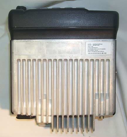
Click to zoom
Application Details
- Equipment Class
- TNB - Licensed Non-Broadcast Station Transmitter
- Date of Grant
- Jun 18, 2002
- Application Purpose
- Original Equipment
- Date of Application
- Apr 07, 2002
- Equipment Note
- CDM1550LS+ Mobile Radio
- Frequency Range
- 792.00000000 - 794.00000000
- Company
- Motorola Solutions, Inc.
- Country
- United States
Documents & Files
Document Text
Text extracted from the exhibit documents filed with the FCC. Open a document above to read the original.
Users Manual
Motorola, The Stylized M logo, Intelligence Everywhere, Professional Radio - As Dedicated As You Are, CDM Series,CDM1550 • LS + , and Call Alert are trademarks of Motorola, Inc. LTR is a mark of E.F. Johnson Company.PassPort is a mark of Trident Micro Systems. © 2002 Motorola, Inc. All rights reserved. Printed in U.S.A. *6864110R13-O*6864110R13-O CDM1550 •• LS ++ ™ User Guide Professional Radio - As Dedicated As You Are ™ 6864110R13-O_cvr.qxd 2/21/02 12:39 PM Page 1 1 English CONTENTS CONTENTS Computer Software Copyrights . . . . . . . . . 6Safety . . . . . . . . . . . . . . . . . . . . . . . . . . . . 7User Safety, Training, andGeneral Information . . . . . . . . . . . . . . . . . . 7Compliance with RF Energy ExposureStandards. . . . . . . . . . . . . . . . . . . . . . . . . . 7Operational Instructions and TrainingGuidelines . . . . . . . . . . . . . . . . . . . . . . . . . 8 Transmit and Receive . . . . . . . . . . . . . . 8Mobile Antennas . . . . . . . . . . . . . . . . . . 9Approved Accessories . . . . . . . . . . . . . 9Fixed Site Antennas . . . . . . . . . . . . . . . 9 Electromagnetic Interference/Compatibility. . . . . . . . . . . . . . . . . . . . . . . 10 Facilities . . . . . . . . . . . . . . . . . . . . . . . 10Vehicles . . . . . . . . . . . . . . . . . . . . . . . 10Driver Safety . . . . . . . . . . . . . . . . . . . . 11 Operational Warnings . . . . . . . . . . . . . . . 11 For Vehicles With an Air Bag . . . . . . . 11Potentially Explosive Atmospheres . . . 11Blasting Caps and Areas . . . . . . . . . . 11 Introduction . . . . . . . . . . . . . . . . . . . . . . . 13Trunked Radio Systems . . . . . . . . . . . . . . 13 PassPort™ Trunked Systems . . . . . . . 13LTR™ Trunked Systems . . . . . . . . . . . 13 Conventional Radio Systems . . . . . . . . . . 14CDM1550•LS+ Radio Features . . . . . . . . . 14 Radio Wide Features . . . . . . . . . . . . . . 14PassPort Zone Features . . . . . . . . . . . 14LTR Zone Features . . . . . . . . . . . . . . . 15Conventional Zone Features . . . . . . . . 15 Radio Overview . . . . . . . . . . . . . . . . . . . . 17Parts of the Radio . . . . . . . . . . . . . . . . . . . 17 CDM1550•LS+ Model. . . . . . . . . . . . . . 17On/Off/Volume Control Knob . . . . . . . . 18LED Indicators . . . . . . . . . . . . . . . . . . . 18Push-to-Talk (PTT) Button . . . . . . . . . . 19Microphone. . . . . . . . . . . . . . . . . . . . . . 19Menu/Select Button ) . . . . . . . . . . . 19 Menu Exit/Button ( . . . . . . . . . . . . . 19 Menu Buttons . . . . . . . . . . . . . . . . . . . . 19Display . . . . . . . . . . . . . . . . . . . . . . . . . 20Microphone Jack . . . . . . . . . . . . . . . . . 21 Optional DTMF Microphone (RMN4026). . 21 DTMF Microphone Keypad . . . . . . . . . 22 6864110R13-OTOC.fm Page 1 Thursday, April 4, 2002 5:52 PM 2 English CONTENTS Programmable Buttons . . . . . . . . . . . . . . . 24 Audio Indicators for ProgrammableButtons . . . . . . . . . . . . . . . . . . . . . . . . 28 Getting Started . . . . . . . . . . . . . . . . . . . . 29Turning the Radio On or Off . . . . . . . . . . . 29Adjusting the Volume . . . . . . . . . . . . . . . . 29Selecting a Trunked Zoneand Talkgroup. . . . . . . . . . . . . . . . . . . . . . 30Sending a Trunked Call . . . . . . . . . . . . . . 30Selecting a Conventional Zoneand Channel . . . . . . . . . . . . . . . . . . . . . . . 31Direct Zone Access. . . . . . . . . . . . . . . . . . 31Direct Channel Access . . . . . . . . . . . . . . . 31Sending a Conventional Call . . . . . . . . . . 33Receiving a Trunked or ConventionalCall . . . . . . . . . . . . . . . . . . . . . . . . . . . . . . 33Repeater or Talkaround J Mode (Conventional Operation Only) . . . . . . . . . 34Call Light (Trunked Operation Only) . . . . . . . . . . . . . 35Home Channel . . . . . . . . . . . . . . . . . . . . . 35Horn and Lights . . . . . . . . . . . . . . . . . . . . 35 To Activate Horn and Lights Programmed with Call Light(Trunked Operation Only) . . . . . . . . . . 35 To Activate Horn and LightsProgrammed with Call Alert(LTR Trunked Operation Only) . . . . . . 36 Remote Monitor(LTR Trunked and ConventionalOperation Only) . . . . . . . . . . . . . . . . . . . . 36Passport Trunking . . . . . . . . . . . . . . . . . 39Seamless Roaming . . . . . . . . . . . . . . . . . 39 Initial Registration . . . . . . . . . . . . . . . . 39Roaming and Registering BetweenSites . . . . . . . . . . . . . . . . . . . . . . . . . . 40 Site/Min View . . . . . . . . . . . . . . . . . . . . . . 41Roam Request . . . . . . . . . . . . . . . . . . . . . 42 To Start a Roam Request . . . . . . . . . 42To Cancel a Roam Request . . . . . . . . 43 Troubleshooting . . . . . . . . . . . . . . . . . . . . 43Radio Calls . . . . . . . . . . . . . . . . . . . . . . . 45Making a Selective Call(LTR Trunked and ConventionalOperation Only) . . . . . . . . . . . . . . . . . . . . 45Receiving a Selective Call F (LTR Trunked and ConventionalOperation Only) . . . . . . . . . . . . . . . . . . . . 46Sending a Call Alert Page(LTR Trunked and ConventionalOperation Only) . . . . . . . . . . . . . . . . . . . . 46 6864110R13-OTOC.fm Page 2 Thursday, April 4, 2002 5:52 PM 3 English CONTENTS Receiving a Call Alert Page(LTR Trunked and ConventionalOperation Only). . . . . . . . . . . . . . . . . . . . . 47Radio Check(LTR Trunked and ConventionalOperation Only). . . . . . . . . . . . . . . . . . . . . 48Sending a Status(Conventional Operation Only) . . . . . . . . . 48Sending a Message(Conventional Operation Only) . . . . . . . . . 49Receiving a Message(Conventional Operation Only) . . . . . . . . . 50Responding to Emergency Alerts E (Conventional Operation Only) . . . . . . . . . 50 Decoding an Emergency Alarm . . . . . . 51Multiple Queued Emergencies . . . . . . . 52Three Minute Timer . . . . . . . . . . . . . . . 52After the Timer Expires . . . . . . . . . . . . 52 Clearing an Emergency Alert E (Conventional Operation Only) . . . . . . . . . 53Sending an Emergency Remote Monitor(Conventional O…
Text truncated - open the document above for the full version.
Users Manual
61 English SCAN SCAN Your radio is equipped with the Scan feature, which allows you to search for, lock onto, and monitor voice activity on trunked talkgroups and conventional channels.There are five types of Scan available in your radio: • Auto Group Scan • All Group Scan • PassPort Primary Auto Scan • PassPort Group Scan • System Scan The table below summarizes the Scan types available in each zone type. Shaded areas indicate that Scan can be enabled through a programmable button (see page 20) or through your radio menu. TALKBACKWhen activity is detected during any type of scan, scanning stops and the active talkgroup or channel appears and remains on the display until scanning resumes. Your dealer can program the amount of time you can respond (or “TALKBACK”) to the caller before your radio resumes scanning.You must press the PTT button to participate in the call; otherwise, scanning continues to the other talkgroups or channels. Zone PassPort Primary Auto Scan Pass- Port Group Scan LT R Auto Group Scan LTR All Group Scan System Scan PassPort Tr u n k e d X X LT R Tr u n k e d X X X Conven-tional X Zone PassPort Primary Auto Scan Pass- Port Group Scan LT R Auto Group Scan LTR All Group Scan System Scan 62 English SCAN PASSPORT PRIMARY AUTO GROUP SCAN(PASSPORT TRUNKED OPERATION ONLY)PassPort Primary Auto Group Scan automatically scans the primary (first) talkgroup within the selected PassPort zone. Any time you are positioned on a PassPort talkgroup other than the first one, your radio automatically scans activity on the first talkgroup within that zone.Note: This feature is enabled AUTOMATICALLY with your radio. It is not enabled through the radio menu or through a prepro-grammed scan button. PASSPORT GROUP SCAN G (PASSPORT TRUNKED OPERATION ONLY)PassPort Group Scan scans talkgroups within the selected PassPort trunked zone, as programmed by your dealer. Up to 16 different talkgroups can be programmed into each Scan list, with one Scan list assigned to each position on the Zone Selector . You can edit these Scan lists through your radio’s menu (see page 66). When PassPort Group Scan is Enabled•The G symbol appears on the display. • The LED indicator blinks green during PassPort Group Scan operation; it stops blinking when the radio switches to an active talkgroup or channel. Note: • PassPort Group Scan is not available when registered on a non-home site. • If you switch to another PassPort zone, LTR, or conventional zone while the radio is scan-ning, scanning resumes upon return to the PassPort zone where PassPort Group Scan was enabled. • If the radio is turned off while scanning, the radio resumes scanning when you turn it back on. If the radio registers on a non-home site, scanning is not enabled until the radio regis-ters at its home site. 63 English SCAN To Start or Stop PassPort Group Scan Operation through a Preprogrammed Button (see page 20)• Press the preprogrammed Scan button to start PassPort Group Scan. • Press the preprogrammed Scan button again to stop the PassPort Group Scan. –or–To Start or S top PassPort Group Scan Operation through the Menu AUTO GROUP SCAN (LTR TRUNKED OPERATION ONLY)Auto Group Scan automatically scans talkgroups within an LTR zone as programmed by your dealer. Auto Group Scan can be either non-prioritized or prioritized. • Non-prioritized Auto Group Scan automatically scans all talkgroups programmed with Auto Group Scan. • Prioritized Auto Group Scan automatically scans the selected talkgroup and all lower 4-numbered talkgroups. For example, if talkgroups 1, 3, and 4 have been programmed by your dealer with Auto Group Scan and talkgroup 4 is selected, the radio automatically scans talkgroups 1, 3, and 4, and skips talkgroup 2. To Start Auto Group ScanSelect a talkgroup that has been programmed for Auto Group Scan by your dealer.Note: You do not need to press a preprogrammed Scan button. 1 ) to enter menu mode. 2 y o r z u n t i l 3 ) to select You see the current scan status. 4 y o r z u n t i l –or– 5 ) to confirm your selection. Pass Grp ScanPass Grp ScanPpGp Scan Off?PpGp Scan On? 64 English SCAN •The G symbol appears on the display when non-prioritized Auto Group Scan has been activated. •The H symbol appears on the display when prioritized Auto Group Scan has been activated. • There is no LED indicator during Auto Group Scan. To Stop Auto Group Scan Select a talkgroup that has not been programmed for Auto Group Scan by your dealer. ALL GROUP SCAN (LTR TRUNKED OPERATION ONLY)All Group Scan scans all talkgroups within the selected LTR trunked zone. When All Group Scan is enabled:•The G symbol appears on the display. • The LED indicator blinks green during All Group Scan operation; it stops blinking when the radio switches to an active talk-group. Note: If you enter menu mode while the radio is scanning, scanning stops. It resumes when you exit menu mode. To Start or Stop All Group Scan Operation through a Preprogrammed Button (see page 20)• Press the preprogrammed All Group Scan button once to start All Group Scan. • Press the preprogrammed All Group Scan button again to stop All Group Scan. –or–To Start or Stop All Group Scan Operation Through the Menu 1 ) to enter menu mode. 2 y or z until 3 ) to select You see the current scan status. 4 y or z until –or– 5 ) to confirm your selection. All Group ScanAll Group ScanAll Group On?All Group Off? 65 English SCAN SYSTEM SCAN G (LTR TRUNKED AND CONVENTIONAL OPERATION ONLY ) System Scan scans trunked talkgroups and conventional channels between LTR and conventional zones, as programmed by your dealer. Up to 16 different talkgroups or conventional channels can be programmed into each Scan list. You can edit these lists through your radio’s menu (see page 66).When System Scan is Enabled• The G symbol appears on the display. • The LED indicator blinks green during Sys- tem Scan operation; it stops blinking when the radio switches to an active talkgroup or channel. Note: If you enter menu mode while the rad…
Text truncated - open the document above for the full version.
Users Manual
June, 2002 6880101W80-C 3 Installation Mobile 1/4-Wave Antennas Installation Mounting Hardware Installation – Roof Mount General The installation procedure which follows is for a typi- cal passenger car. The procedure may vary slightly with the type of vehicle on which the antenna is to be installed. Generally speaking, however, the procedures outlined are of a universal nature. NOTE The antenna should be mounted on a flat metal roof of .020 to .040 inch thickness. 1.First, select a location for the antenna as near the center of the roof as possible. 2.The headlining may be probed with the fin- gers to make sure that all points of obstruction are avoided. Installation Procedure Single Wall Construction 1.Locate the center of the roof by careful mea- surement, remove the headlining as necessary, and drill a pilot hole down through the roof. If the interior light of the car is centered in the roof, remove this light and fixture and drill the pilot hole up through the roof at about the center of the interior light mountings. This centers the antenna mount on the roof and allows for easy access. 2.Drill a 3/4-inch hole from the top of the roof until the saw bottoms. Use a Motorola hole cutting saw (01-80382A25) or equivalent. When the saw bottoms on the roof, it cleans off the paint in a neat circle and assures good contact with the locking nut. IMPORTANT For proper seating of brushing assembly, remove burrs and scrape any foreign matter from underside of hole out to at least 1/8-inch from edge. 3.Determine the routing of the cable from the antenna mounting base to the radio set; then remove the molding and trim necessary to facilitate pulling the cable through. NOTE To ensure ease of assembly, thread the locking nut on and then off the bushing assembly before installation. This removes any burrs which may be present. 4.Refer to Figure 5. From the top, feed the RG-58A/U lead-in cable between the headlin- ing and the metal roof. Then route the cable between the roof and the radio set. 5.Refer to Figure 6. The bushing assembly is now in a position to drop into the hole in the roof. It should be tilted at a slight angle and fed into the 3/4-inch hold. The threaded top will not fall through the hole. 6.Refer to Figure 7. Hold the antenna bushing assembly in place with the index finger and thread the locking nut onto it as shown. 7.Pull up on the bushing assembly as illustrated in Figure 8, and make sure it is centered and seated (both shoulders inside the drilled hole), and that the "O" ring is in the groove in the locking nut. (As furnished, the "O" ring has been placed in the locking nut groove and imbedded in silicone grease.) Use a 15/16-inch open-end wrench to tighten the locking nut until it bottoms firmly against the roof top. IMPORTANT Refer to Figure 3. If the bushing assembly should slip or rotate for any reason dur- ing the tightening procedure, insert the tips of a long nose plier or spanner wrench into the two holes in the bushing assembly and apply force to prevent rotation until the locking nut is tight. The locking nut must come into contact with the car roof to insure the proper antenna radiation pattern. This can only happen when the rubber "O" ring is fully compressed. 8.Take up the slack in the cable and replace the headlining retainer molding. 9.Replace headlining and dome light if removed. Installation Procedure - Double Wall Construction Vehicles With Dome Lights or Removable Headlining 1.Remove the dome light from its mount or remove the headlining from the installation area. 2.Drill a small pilot hole centered in the roof of the vehicle. The center of the cavity where the dome light was removed is sufficiently close. 3.Using a 1-1/4-inch diameter hole saw cut a hole in the inside layer of the metal. 4 6880101W80-C June, 2002 Mobile 1/4-Wave AntennasInstallation Figure 5.Coaxial Cable InsertionFigure 6.Bushing Assembly Insertion Figure 7. Locking Nut Positioning Figure 8. Locking Nut Tightening June, 2002 6880101W80-C 5 Installation Mobile 1/4-Wave Antennas 4.Remove the metal and filler from this 1-1/4-inch diameter hole. 5.Complete the installation per installation pro- cedure given for vehicles with single wall con- struction. A completed mount is illustrated in Figure 9. Vehicles Without Dome Lights When the vehicle has no dome light, and it is not feasi- ble to remove the headlining to get to the inside sur- face, proceed as follows: 1.Locate the center of the roof and make sure the area beneath this point is clear to allow passage of a drill. 2.With a 3/4-inch diameter hole cutting saw carefully cut a 3/4-inch hole from the top of the roof through both thicknesses of metal. Clean the metal in a neat circle around the hole to assure a good contact between the roof metal and the locking nut. 3.Remove any burrs and remove the filler sepa- rating the roof thickness for a distance of 1/4-inch back from the hole. 4.Install the mount to the outside roof thickness per installation procedure given for vehicles with single wall construction. Mounting Hardware Installation – Trunk Lip Mount NOTE Not recommended for transmitters with power outputs of 7 W or greater. 1.Refer to Figure 11 for antenna location. 2.Using the Allen wrench supplied, turn the two set screws counterclockwise until their threads are not visible on the underside of the clamp bracket. 3.Raise the trunk lid to pass the coaxial cable through; then tilt the mounting base slightly to hook the clamp bracket on the trunk lip. The coaxial cable, coming from under the mounting base, may have to be bent down to accomplish this step. When the base is in posi- tion, the coaxial cable should not bind in any way, or be pinched under a set screw. 4.Tighten the two set screws. Figure 10.Roof Mount in Vehicle Without Dome Light Figure 9.Roof Mount in Vehicle With Dome Light or Removable Headlining 6 6880101W80-C June, 2002 Mobile 1/4-Wave AntennasInstallation NOTE The coaxial cable will normally not be harmed by opening an…
Text truncated - open the document above for the full version.
Attestation Statements
MOTOROLA INC FCC ID: ABZ99FT5001 EXHIBIT 2 SHEET 1 OF 1 CERTIFICATION OF DATA Pursuant to 47 CFR 2.1517(g) The technical data supplied with this application, having been taken under my supervision, is hereby duly certified. The following is a statement of my qualifications: 1) I have received a BSEE degree in Electrical Engineering from Northwestern University, Evanston, Illinois. 2) I have 29 years experience in developing, testing and certifying Land Mobile Communications Products. NAME: James M. Zima SIGNATURE: DATE: April 5, 2002 POSITION: Principal Staff Engineer I hereby certify that the above application was prepared under my direction and that to the best of my knowledge and belief, the facts set forth in the application and accompanying technical data are true and correct: NAME: Robert M. Kraus SIGNATURE: DATE: April 5, 2002 POSITION: Engineering Section Manager
Cover Letter(s)
MOTOROLA INC. FCC ID: ABZ99FT5001 LIST OF EXHIBITS DESCRIPTION EXHIBIT REFERENCE I. Identification Label Information 1 2.1033(c)(11) General Information 1A 1. Production Plans 2. Application References 2.1061 3. Data Submittal Procedure II. Certification of Data 2 III. External Photographs 3 2.1033(c)(12) IV. Circuit Descriptions 4 2.1033(c)(10) 1. Means for Frequency Stabilization 4A 2. Means for Limiting Modulation 4B 3. Means for Attenuation of Higher Audio Frequencies 4C 4. Means for Attenuation of Spurious Emissions 4D 5. Means for Limiting Power Output 4E 6. Modulation Techniques 4F 7. Means for Controlling Transient Frequency Behavior 4G V. Schematic Diagrams 5 2.1033(c)(10) 1. Transmitter Audio, PL/DPL/DTMF/Trunking 5A 2. Microprocessor/Controller 5B 3. Fractional-N Synthesizer, Reference Oscillator 5C 4. VCO’s, Buffers and Modulator 5D 5. RF Power Amp/LPF/Antenna Switch, Power Control 5E VI. Test Report 6 1. Data Index 6 2. RF Output Data A. Conducted 6A-1,2 2.1046(a) B. ERP 6A-3,4 27.50(b)(2) 3. Modulation Characteristics A. Audio Response & Low Pass Filter Response 6B, 6C 2.1047(a) B. Modulation Limiting 6D 2.1047(b) 4. Occupied Bandwidth 6E 2.1049(c)(1) 5. Conducted Spurious Emissions 6F 2.1051 6. Radiated Spurious Emissions 6G 2.1053 7. Frequency Stability A. Frequency Stability vs. Temperature 6H-1 2.1055(a,b) B. Frequency Stability vs. Voltage 6H-2 2.1055(d) 8. GNSS Radiated Spurious Emissions 6I 27.53(d)(4)(e) 9. Adjacent Channel Coupled Power 6J 90.543(a) MOTOROLA INC. FCC ID: ABZ99FT5001 LIST OF EXHIBITS (CONTINUED) DESCRIPTION EXHIBIT REFERENCE VII. Test Set-up Procedures 7 VIII. Instruction Manual 8 2.1033(c)(3) IX. Internal Photographs 9 2.1033(c)(12) X. Parts List and Tune Up Procedures 10 1. Function of RF Semiconductors & Active Devices 10A 2.1033(c)(10) 2. List of Recommended Test Equipment for Servicing 10B 3. Tune Up Information 10C 2.1033(c)(9) XI. RF Exposure Information 11A 2.1091 S.A.R. EME Compliance Test Report 11B XII. Operational Description 12 2.1033(c)(4-7) 1. Technical Characteristics 2. Application XIII. Cover Letter 13A Request for Confidentiality 13B
Cover Letter(s)
EXHIBIT 13A SHEET 1 OF 1 FCC ID: ABZ99FT5001 Date: April 5, 2002 Authorization & Evaluation Division Federal Communications Commission Laboratory 7435 Oakland Mills Road Columbia, MD 21046 Subject: Application for Certification of Transmitter with FCC ID: ABZ99FT5001 Gentlemen: Motorola Inc., 1313 E. Algoquin Road, Schaumburg, Illinois, herein submits application for Certification of the equipment identified by FCC ID number ABZ99FT5001. This transmitter is intended for use in a mobile radio application with capabilities for conventional and trunked communications with a conducted power of 1 Watt (+30 dBm) or 18 Watts (+42.6 dBm). The frequency bands of operation comply with CFR Title 47, Sections 27.5(b) (1) and (2). The subject transmitter complies with CFR Title 47, Section 90.203, in that the operator cannot directly program the transmit frequencies using only the normally accessible external controls of the unit. Enclosed is a complete Certification Application. Please contact me if you require any additional information. Sincerely, Donna Tokarz NPR Coordinator Tel: (847) 576-7245 Fax: (847) 538-4312 E-mail: [email protected]
Cover Letter(s)
EXHIBIT 13B SHEET 1 OF 1 FCC ID: ABZ99FT5001 REQUEST FOR CONFIDENTIALITY Date: April 5, 2002 Authorization & Evaluation Division Federal Communications Commission Laboratory 7435 Oakland Mills Road Columbia, MD 21046 Subject: Application for Certification of Transmitter with FCC ID: ABZ99FT5001 Gentlemen: Motorola is requesting that Exhibit 4 (Circuit Descriptions), Exhibit 5 (Schematic Diagrams), Exhibit 10 (Parts List and Tune Up Procedures), and Exhibit 12 (Operational Description) not be made routinely available for public inspection. Motorola is in the process of licensing the technology employed. Please mark Exhibits 4, 5, 10, and 12 as “Confidential.” Please contact me if you require any additional information. Sincerely, Donna Tokarz NPR Coordinator Tel: (847) 576-7245 Fax: (847) 538-4312 E-mail: [email protected]
Cover Letter(s)
EXHIBIT 13A (AMENDED) SHEET 1 OF 1 FCC ID: ABZ99FT5001 Date: May 7, 2002 Authorization & Evaluation Division Federal Communications Commission Laboratory 7435 Oakland Mills Road Columbia, MD 21046 Subject: Application for Certification of Transmitter with FCC ID: ABZ99FT5001 Gentlemen: Motorola Inc., 1313 E. Algonquin Road, Schaumburg, Illinois, herein submits application for Certification of the equipment identified by FCC ID number ABZ99FT5001. This transmitter is intended for use in a mobile radio application with capabilities for conventional and trunked communications with a conducted power that is continuously variable from 1 Watt (+30 dBm) to 18 Watts (+42.6 dBm). The frequency bands of operation comply with CFR Title 47, Sections 27.5(b) (1) and (2). The subject transmitter complies with CFR Title 47, Section 90.203, in that the operator cannot directly program the transmit frequencies using only the normally accessible external controls of the unit. Enclosed is a complete Certification Application. Please contact me if you require any additional information. Sincerely, Donna Tokarz NPR Coordinator Tel: (847) 576-7245 Fax: (847) 538-4312 E-mail: [email protected]
External Photos
MOTOROLA INC FCC ID: ABZ99FT5001 EXHIBIT 3 SHEET 1 OF 4 GENERAL VIEW OF CDM1550• •• •LS+ MODEL WITH MICROPHONE MOTOROLA INC FCC ID: ABZ99FT5001 EXHIBIT 3 SHEET 2 OF 4 FRONT VIEW OF CDM1550• •• •LS+ MODEL MOTOROLA INC FCC ID: ABZ99FT5001 EXHIBIT 3 SHEET 3 OF 4 BOTTOM VIEW SHOWING FCC ID LABEL (CLOSE-UP OF FCC ID LABEL ON FOLLOWING PAGE) MOTOROLA INC FCC ID: ABZ99FT5001 EXHIBIT 3 SHEET 4 OF 4 CLOSE-UP VIEW OF FCC ID LABEL
ID Label/Location Info
MOTOROLA INC FCC ID: ABZ99FT5001 EXHIBIT 1 SHEET 1 OF 2 IDENTIFICATION LABEL Pursuant to 47 CFR 2.925(a), 2.1033(c), 2.1065 LOCATION A nameplate of the type presented below will be affixed to every transmitter. It will be placed on the bottom of the unit near the front. Shown below is a photo of the actual label affixed to the cast chassis of the transmitter. TYPE The label is a paper polyester film laminate with a pressure sensitive adhesive backing. The adhesive is a permanent type acrylic with a minimum peel strength of 40 oz/inch. MOTOROLA INC FCC ID: ABZ99FT5001 EXHIBIT 1 SHEET 2 OF 2 EXHIBIT 1A - GENERAL INFORMATION 1. Production Plans -- Pursuant 2.981 (c) Quantity production is planned. 2. Application References: TIA/EIA-603 Land Mobile FM or PM Communications Equipment Measurement and Performance Standards Code of Federal Regulations Title 47, Part 2, Sec. 2.1033-2.1057, and Part 90, Sec. 90.210. 3. Data Submittal Procedure: Data is supplied in accordance with Part 2, Sub-part J of the Commissions’ rules. The intended use of this transceiver includes applications covered in the Code of Federal Regulations Title 47, Part 90. Maximum transmitter power shall not be adjustable by the user. 4. Similar to “Currently Certified Transmitter Type”: AZ492FT4829 – Motorola CDM750/CDM1250 Professional Two-Way UHF Mobile Radio
ID Label/Location Info
MOTOROLA INC FCC ID: ABZ99FT5001 AMENDED EXHIBIT 1 SHEET 1 OF 2 IDENTIFICATION LABEL Pursuant to 47 CFR 2.925(a), 2.1033(c), 2.1065 LOCATION A nameplate of the type presented below will be affixed to every transmitter. It will be placed on the bottom of the unit near the front. Shown below is a photo of the actual label affixed to the cast chassis of the transmitter. TYPE The label is a paper polyester film laminate with a pressure sensitive adhesive backing. The adhesive is a permanent type acrylic with a minimum peel strength of 40 oz/inch. MOTOROLA INC FCC ID: ABZ99FT5001 AMENDED EXHIBIT 1 SHEET 2 OF 2 EXHIBIT 1A - GENERAL INFORMATION 1. Production Plans -- Pursuant 2.981 (c) Quantity production is planned. 2. Application References: TIA/EIA-603 Land Mobile FM or PM Communications Equipment Measurement and Performance Standards Code of Federal Regulations Title 47, Part 2, Sec. 2.1033-2.1057, and Part 27, Sections 27.5 (b) (1) and (2), and 27.53 (d) and (e). 3. Data Submittal Procedure: Data is supplied in accordance with Part 2, Sub-part J of the Commissions’ rules. The intended use of this transceiver includes applications covered in the Code of Federal Regulations Title 47, Part 90. Maximum transmitter power shall not be adjustable by the user. 4. Similar to “Currently Certified Transmitter Type”: AZ492FT4829 – Motorola CDM750/CDM1250 Professional Two-Way UHF Mobile Radio
Internal Photos
MOTOROLA INC FCC ID: ABZ99FT5001 EXHIBIT 9 SHEET 1 OF 2 TOP VIEW WITH CHASSIS TOP COVER REMOVED (MATING SURFACES OF TOP COVER AND CIRCUIT BOARD IN CHASSIS ARE SHOWN) MOTOROLA INC FCC ID: ABZ99FT5001 EXHIBIT 9 SHEET 2 OF 2 TOP VIEW WITH CIRCUIT BOARD REMOVED FROM CHASSIS (MATING SURFACES OF CIRCUIT BOARD AND CHASSIS ARE SHOWN)
RF Exposure Info
MOTOROLA INC. FCC ID: ABZ99FT5001 EXHIBIT 11A SHEET 1 OF 1 RF EXPOSURE INFORMATION Pursuant 47 CFR 2.1091 In accordance with 47 CFR 2.1091(c) this transmitter has been subjected to routine environmental evaluation for RF exposure and found to be compliant with the limits specified in 47 CFR 2.1091(d) for mobile devices, using measurements per methods stated in 47 CFR 2.1091(d)(1). The complete S.A.R. EME Compliance Test Report is attached as Exhibit 11B.
RF Exposure Info
Certificate Number: 1449-02 CGISS EME Test Laboratory 8000 West Sunrise Blvd Fort Lauderdale, FL. 33322 EME Compliance Test Report Attention: Federal Communication Commission Date of Report: March 26, 2002 Report Revision: Rev. O Device Manufacturer: Motorola Device Description: CDM1550 LS 1-15 watts Mobile Radio 746-794MHZ Classification: General Population/Uncontrolled Exposure FCC ID: ABZ99FT5001 Device Model: PMUF1111A Test Period: Test Engineer: Author: 3/20/02 Michael Sailsman EME Regulatory Affairs Liaison Jim Fortier Sr. Staff En gineer Note: Based on the information and the testing results provided herein, the undersigned certifies that when used as stated in the operating instructions supplied, said product complies with all applicable national and international reference standards and guidelines. Ken Enger 3/26/02 ____________________________________________________________ _________________________ Senior Resource Manager, Product Safety and EME Director Date Approved Note: This report shall not be reproduced without written approval from an officially designated representative of the Motorola EME Laboratory. Page 1 of 7 1.0 Description of Test Sample The CDM1550 LS, model PMUF1111A is a mobile transceiver that operates on trunked LTR (a transmission based trunking protocol for single site trunking) and Passport systems (an enhanced trunking protocol for wide area dispatch) as well as on conventional (single channel unit to unit communications) radio systems. The intended use of the radio is Push-To-Talk (PTT) while the device is properly installed in a vehicle with an external antenna mounted at the center of the roof or trunk. The transmit frequency band for the CDM1550 LS is 746-794MHz. The rated power of the device is 1 to 15 watts with a maximum conducted power output of 18 watts. The sample device tested for th…
Text truncated - open the document above for the full version.
Contact Information
Applicant
Matthew Nawrocki
Technical Contact
Motorola, Inc.Jim Zima
[email protected]847 576-3697
1313 E. Algonquin Rd. · Schaumburg, Illinois · United States
Non-Technical Contact
Motorola, Inc.Donna Tokarz
[email protected]847 576-7245
Technical Specifications
| # | Rule Parts | Frequency Range | Power Output | Emission | Tolerance |
|---|---|---|---|---|---|
| 4 | 27.53(d) | 792 MHz - 794 MHz | 18 W | 11K0F3E | 1.5 ppm |
Other Applications from Motorola Solutions, Inc.

ABZ89FT4940
Aug 06, 2026Non Broadcast Transmitter
Equipment Class
TNB - Licensed Non-Broadcast Station TransmitterABZ89FT4950
Jun 25, 2026Non-Broadcast Transmitter
Equipment Class
TNB - Licensed Non-Broadcast Station TransmitterABZ89FT5901
Jun 20, 2024Non Broadcast Transmitter
Equipment Class
TNB - Licensed Non-Broadcast Station Transmitter
ABZ99FT5101B
May 02, 2023Non Broadcast Transmitter
Equipment Class
PCB - PCS Licensed Transmitter
ABZ99FT3095B
Mar 26, 2023Non Broadcast Transmitter
Equipment Class
TNB - Licensed Non-Broadcast Station Transmitter