ABZ99FT7002Radio Bluetooth Adapter
Motorola Solutions, Inc.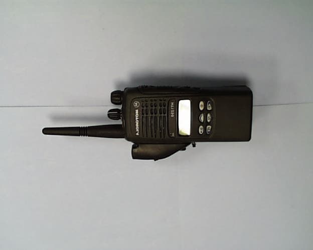
Click to zoom
Application Details
- Equipment Class
- DSS - Part 15 Spread Spectrum Transmitter
- Date of Grant
- Aug 05, 2001
- Application Purpose
- Original Equipment
- Date of Application
- Jun 07, 2001
- Equipment Note
- Radio Bluetooth Adapter
- Frequency Range
- 2402.00000000 - 2480.00000000
- Company
- Motorola Solutions, Inc.
- Country
- United States
Documents & Files
Document Text
Text extracted from the exhibit documents filed with the FCC. Open a document above to read the original.
Users Manual
Accessories Radio Adapter (RBA) 6880309K16-O for the Professional Radio Series Model HHLN4125 and MOTOROLA are registered trademarks of Motorola, Inc. The BLUETOOTH trademarks are owned by Telefonaktiebolaget LM Ericsson, Sweden, and licensed to Motorola, Inc. 1 TABLE OF CONTENTS Safety and General Information. . . . . . . . . . . . . . . . . 3 Electromagnetic Interference/Compatibility Facilities . . . . . . . . . . . . . . . . . . . . . . . . . . . . . . . . . 4 Aircraft . . . . . . . . . . . . . . . . . . . . . . . . . . . . . . . . . . 4 Medical Devices . . . . . . . . . . . . . . . . . . . . . . . . . . . 4 Safety and General Use While Driving . . . . . . . . . . . . . . . . . . . . . . . . . 9 Bluetooth Wireless Technology Overview. . . . . . . . . 6 Getting Started Installing the Radio Bluetooth Adapter (RBA) . . . . 8 Removing the Radio Bluetooth Adapter (RBA) . . . 9 Turning ON the RBA. . . . . . . . . . . . . . . . . . . . . . . . 9 Establishing the Bluetooth Wireless Connection. . . . . . . . . . . . . . . . . . . . . . . . . . . . . 9 Connection Verification . . . . . . . . . . . . . . . . . . . . 10 Lost Link . . . . . . . . . . . . . . . . . . . . . . . . . . . . . . . 11 Turning OFF the RBA . . . . . . . . . . . . . . . . . . . . . . 11 Disconnecting the Bluetooth Wireless Connection. . . . . . . . . . . . . . . . . . . . . . . . . . . . 12 LED Indicators . . . . . . . . . . . . . . . . . . . . . . . . . . . 13 Operation Operational Range . . . . . . . . . . . . . . . . . . . . . . . . 14 Receiving . . . . . . . . . . . . . . . . . . . . . . . . . . . . . . . 14 Transmitting. . . . . . . . . . . . . . . . . . . . . . . . . . . . . 14 Volume Control . . . . . . . . . . . . . . . . . . . . . . . . . . 15 VOX (Voice Activated Transmission) . . . . . . . . . . 15 2 Battery Low Battery Alert . . . . . . . . . . . . . . . . . . . . . . . . . 16 Battery Life . . . . . . . . . . . . . . . . . . . . . . . . . . . . . 16 Temperature Effects On Your RBA . . . . . . . . . . . . . . 16 RBA Replacement Parts Lists . . . . . . . . . . . . . . . . . 17 Service and Support. . . . . . . . . . . . . . . . . . . . . . . . . 17 Warranty. . . . . . . . . . . . . . . . . . . . . . . . . . . . . . . . . . 17 Replacing the HHLN4125 Side Connector Board. . . 18 3 SAFETY AND GENERAL INFORMATION IMPORTANT INFORMATION ON SAFE AND EFFICIENT OPERATION. READ THIS INFORMATION BEFORE USING YOUR RADIO. Users are not permitted to make changes or modify the device in any way. Changes or modifi- cations not expressly approved by the party responsible for compliance could void the user’s authority to operate the device. See 47 CFR Sec. 15.21. This device complies with Part 15 of the U.S. FCC Rules. Operation is subject to the following two conditions: (1) This device may not cause harmful interfer- ence, and (2) this device must accept any inter- ference received, including interference that may cause undesired operation. See 47 CFR Sec. 15.19(3). 4 ELECTROMAGNETIC INTERFERENCE/ COMPATIBILITY OTE:Nearly every electronic device is sus- ceptible to electromagnetic interference (EMI) if inadequately shielded, designed or otherwise configured for electromag- netic compatibility. Facilities To avoid electromagnetic interference and/or compatibility conflicts, turn off your device in any facility where posted notices instruct you to do so. Hospitals or health care facilities may be using equipment that is sensitive to external RF energy. Aircraft When instructed to do so, turn off your device when on board an aircraft. Any use of your device must be in accordance with applicable regula- tions per airline crew instructions. Medical Devices Pacemakers The Health Industry Manufacturers Association recommends that a minimum separation of 6 inches (15 centimeters) be maintained between a N 5 wireless device and a pacemaker. These recom- mendations are consistent with the independent research by, and recommendations of, Wireless Technology Research. Persons with pacemakers should: •ALWAYS keep the wireless device more than 6 inches (15 centimeters) from their pacemaker when the device is turned ON. •not carry the device in the breast pocket. •use the ear opposite the pacemaker to min- imize the potential for interference. •turn the device OFF immediately if you have any reason to suspect that interfer- ence is taking place. Hearing Aids Some digital wireless radios may interfere with some hearing aids. In the event of such interfer- ence, you may want to consult your hearing aid manufacturer to discuss alternatives. Other Medical Devices If you use any other personal medical device, consult the manufacturer of your device to deter- mine if it is adequately shielded from RF energy. Your physician may be able to assist you in obtaining this information. 6 BLUETOOTH WIRELESS TECHNOLOGY OVERVIEW At Motorola we believe that easy portable com- munication is the key to creating a safer environ- ment. That’s why we designed this exciting new two-way communication device called the Radio Bluetooth Adapter (RBA). The RBA represents another breakthrough in applying Bluetooth wire- less technology by Motorola. This adapter allows your radio to send and receive audio from a wire- less accessory such as a Remote Speaker Micro- phone (RSM) without wires. This RBA uses a new protocol based on state-of- the-art Bluetooth technology specifications, which result in simplifying the use of your radio. Bluetooth wireless technology is an open stan- dard, connecting wireless devices within a short range. The range for this particular adapter (RBA) and the Bluetooth audio accessory is approximately 30 feet in ideal line-of-sight condi- tions. It is important to be aware that the specific Bluetooth technology was designed and engi- neered for use between your radio and special Bluetooth audio accessories. Your Bluetooth audio accessory will not operate with other non- Motorola two-way radio Bluetooth products. 7 If your radio is VOX (voice activat…
Text truncated - open the document above for the full version.
Cover Letter(s)
FCC ID: ABZ99FT7002 Request for Confidentiality In accordance with 47 C.F.R. Section 0.459, we, Motorola, Inc., hereby request confidentiality for the block diagram, schematic and product description presented for certification. In support of the Request for Confidentiality, the following is stated: Enclosed within this application is technical information which we deem to be trade secrets and proprietary. If made public, the information might be used to our disadvantage. To assist in assuring that we receive the full value of our product and protect its competitive posture, we respectfully request this grant of confidentiality. Les Clemens Engineering Section Manager Motorola, Inc. Accessories and Peripheral Solutions GTDG 847-576-2057
Cover Letter(s)
BLUETOOTH SPECIFICATION Version 1.1 Baseband Specification 11 HOP SELECTION In total, 10 types of hopping sequences are defined −five for the 79-hop and five for the 23-hop system, respectively. Using the notation of parentheses () for figures related to the 23-hop system, these sequences are: • A page hopping sequence with 32 (16) unique wake-up frequencies dis-tributed equally over the 79 (23) MHz, with a period length of 32 (16); • A page response sequence covering 32 (16) unique response frequencies that all are in an one-to-one correspondence to the current page hopping sequence. The master and slave use different rules to obtain the same sequence; • An inquiry sequence with 32 (16) unique wake-up frequencies distributed equally over the 79 (23) MHz, with a period length of 32 (16); • A inquiry response sequence covering 32 (16) unique response frequencies that all are in an one-to- one correspondence to the current inquiry hop-ping sequence. • A cha nne l ho ppi ng se que nce which has a very long period length, w hich does not show repetitive patterns over a short time interval, but which distributes the hop frequencies equally over the 79 (23) MHz during a short time interval; For the page hopping sequence, it is important that we can easily shift the phase forward or backward, so we need a 1-1 mapping from a counter to the hop frequencies. For each case, both a hop sequence from master to slave and from slave to master are required. The inquiry and inquiry response sequences always utilizes the GIAC LAP as lower address part and the DCI as upper address part in deriving the hopping sequence, even if it concerns a DIAC inquiry. 11.1 GENERAL SELECTION SCHEME The selection scheme consists of two parts: • selecting a sequence; • mapping this sequence on the hop frequencies; The mapping from the input to a particular hop frequency is performed in the selection box. Basically, the input is the native clock and the current address. In CONNECTION state, the native clock (CLKN) is modified by an offset to equal the master clock (CLK). Only the 27 MSBs of the clock are used. In the page and inquiry substates, all 28 bits of the clock are used. However, in page substate the native clock will be modified to the master’s estimate of the paged unit. The address input consists of 28 bits, i.e., the entire LAP and the 4 LSBs of the UAP. In CONNECTION state, the address of the master is used. In page sub-state the address of the paged unit is used. When in inquiry substate, the UAP/LAP corresponding to the GIAC is used. The output constitutes a pseudo-random sequence, either covering 79 hop or 23 hops, depending on the state. For the 79-hop system, the selection scheme chooses a segment of 32 hop frequencies spanning about 64 MHz and visits these hops once in a random order. Next, a different 32-hop segment is chosen, etc. In case of the page, page scan, or page response substates, the same 32-hop segment is used all the time (the segment is selected by the address; different units will have dif-ferent paging segments). In connection state, the output constitutes a pseudo-random sequence that slides through the 79 hops or 23 hops, depending on the selected hop system. For the 23-hop systems, the segment size is 16. .
Test Report
FCC ID: ABZ99FT7002 Power Spectral Density Measurements 15.247(d) The FCC Rules require the peak power density to be no greater than 8 dBm in any 3 kHz band The total peak power level of this device is no greater than 1.2 dBm (EIRP). Since the total peak power is 1.2 dBm, the power is any 3 kHz band could not exceed this total level of 1.2 dBm. Since the power in any 3 kHz band could not exceed 1.2 dBm, this device complies with the power spectral density requirements. No additional measurements should be required to demonstrate compliance. Respect submitted by: Raymond J. Klouda Registered Professional Engineer of Illinois- 44894 Elite Electronic Engineering Inc.
Test Report
Page 1 of 11 Properties/Title v2 21 December 2000 COMMERCIAL IN CONFIDENCE This material may not in whole or part be copied, stored electronically or communicated to third parties without Cambridge Silicon Radio’s prior agreement in writing. . Filename: BlueCore01_BC01b_PG_Results_revB MEMORANDUM Distribution:Peter Flittner, Robert Young, James Collier cc: Prepared By:Alex Busteed Subject:Results of Processing Gain Tests for FCC Qualification 1 INTRODUCTION This memo presents the results of the Processing Gain (PG) tests carried out for FCC qualification of the Cambridge Silicon Radio BC01B Bluetooth chip. The FCC states that the PG from a hybrid Bluetooth receiver must be greater than 17 dB when measured in accordance with the Continuous Wave (CW) jamming margin method. Testing of the BC01b has found the PG due to the DS section to be approximately 5 dB and the PG due to the FH part to be approximately 15 dB. It is therefore concluded that the BC01B complies with the FCC PG requirements for radio communication systems. The rest of this paper outlines the PG measurement technique and discusses the test results. Appendix A contains a list of test equipment and Appendix B contains a printout of the measurement results. 2 METHOD 2.1 PG Definition The Processing Gain from a frequency hopping communication system is derived from two parts, the FH section and the DS section. The PG due to FH is given by a simple equation and is constant. However measurement of the PG due to DS is a little more complex. One technique is to use the CW jamming margin method. This method measures PG due to DS using the following algorithm: A CW signal generator is stepped in 50kHz increments across the passband of the system, recording at each point the generator level required to produce the 0.1% Packet Error Rate (PER). This is the jammer level. This level is then referenced to the output power of the intended Bluetooth signal and the Jammer to Signal Ratio JSR is thus calculated. The worst 4 Page 2 of 11 Properties/Title v2 21 December 2000 COMMERCIAL IN CONFIDENCE JSR measurements are discarded and the worst remaining JSR is used to calculate the PG due to DS as follows: sysp LJSRSNRG++= min where G p = the processing gain of the system, SNR = the signal to noise ratio required for 0.1% BER, JSR min = minimum J/S ratio and L sys = system losses. 2.2 PG Measurement Technique Figure 1 provides an overview of the PG measurement technique. The measurement is performed in two parts, measurement of the system SNR and measurement of JSR min . Figure 1: PG Measurement Technique The system SNR is calculated using the following algorithm. Generate Bluetooth PRBS-9 packets using a BC01B emulator (1) and a Vector Signal Generator (2). Combine this signal with white noise of a constant level, which is generated using a noise source (4) and a CW Signal Generator (3). Then vary the level of the Bluetooth signal until the BER measured by the BC01B (7) is 0.1%. The resulting SNR is the signal level divided by the Noise level. Page 3 of 11 Properties/Title v2 21 December 2000 COMMERCIAL IN CONFIDENCE The JSR for a given jamming frequency is calculated using the following algorithm. Generate Bluetooth PRBS-9 packets using the BC01B emulator (1) and the Vector Signal Generator (2). Combine this signal with a constant CW tone at the jamming frequency using a CW Signal Generator (5) and a combiner (6). Then vary the level of the Bluetooth signal until the PER measured by the Casira Bluetooth Module (7) is 0.1%. The resulting JSR is the signal level divided by the jamming level. 3 RESULTS 3.1 Overview The measurements found that the PG due to DS caused by the access code in page and inquiry mode is found to be approximately 5dB when the access code is a relatively random mixture of 1's and 0's. A random access code causes the most Inter Symbol Interference (ISI) and hence the worst PG for a hybrid system. Therefore only the results for this access code are used in the PG calculation. The PG due to FH is given as PG FH = 10 log 10 (number of frequency hops) The number of hops in a Bluetooth system is 32, therefore the PG due to FH is approximately 15 dB. When this is added to the PG due to DS, the total PG for the BC01B is approximately 20 dB, above the minimum PG requirement for FCC qualification. 3.2 Detailed Results Test Date:17/11/00 Sample Time: 30 seconds Access Code: c6967e Signal Frequency:2.432GHz Receiver Sensitivity: -88.7 dBm Jammer Signal Level:-85.7 dBm Measured SNR: 18.8dB System Losses: 2dB To calculate processing gain, ignore the worst 20% of data points and then apply the following formula: Page 4 of 11 Properties/Title v2 21 December 2000 COMMERCIAL IN CONFIDENCE sysp LJSRSNRG++= min Where G p = Processing Gain of the module SNR = signal to noise ratio of the module JS min = minimum J/S ratio after the worst 20% of J/S samples have been discarded L sys = System losses A total of 20 samples were taken by stepping the jamming signal frequency offsets in 50kHz increments over the bandwidth of the receiver. The worst 4 samples were found at –500kHz, -450kHz, -400kHz and 500kHz and were discarded. The remaining minimum J/S ratio was found to be -15.4dB at an offset of +350kHz Thus, the processing gain due to direct sequence spreading in page and inquiry mode is dBG p 4.524.158.18=+−= -500-400-300-200-1000100200300400500 -30 -25 -20 -15 -10 -5 0 5 Jamming Frequency Offset (kHz) J/S (dBs) J/S ratio performance for Processing Gain FCC Testing Page 5 of 11 Properties/Title v2 21 December 2000 COMMERCIAL IN CONFIDENCE APPENDIX A - TEST EQUIPMENT LIST Reference:Instrument TypeName 1BlueCore Emulator BoardN/A 2Vector Signal GeneratorIFR2052 3CW Signal GeneratorIFR2025 4White Noise GeneratorHP33120A 5RF MixerM8HC-7 6RF Combiner6 dB loss combiner 7Bluetooth Motherboard and BC01B Module Casira Development Kit 85V, 4A DC Power SupplyN/A 9Spectrum AnalyserHP E4405B Page 6 of 11 Properties/Title v2 21 December 2000 COMMERCIAL IN CON…
Text truncated - open the document above for the full version.
Contact Information
Applicant
Matthew Nawrocki
Technical Contact
Motorola, Inc.David Brongiel
5201 Tollview Drive · Rolling Meadows, Illinois · United States
Non-Technical Contact
Motorola, Inc.Les Clemens
[email protected]847 576-2057
Test Firm
Elite Electronic Engineering Co.Daniel Crowder
Technical Specifications
| # | Rule Parts | Frequency Range | Power Output |
|---|---|---|---|
| 1 | 15C | 2.40 GHz - 2.48 GHz | 1.30 mW |
Other Applications from Motorola Solutions, Inc.

ABZ89FT4940
Aug 06, 2026Non Broadcast Transmitter
Equipment Class
TNB - Licensed Non-Broadcast Station TransmitterABZ89FT4950
Jun 25, 2026Non-Broadcast Transmitter
Equipment Class
TNB - Licensed Non-Broadcast Station TransmitterABZ89FT5901
Jun 20, 2024Non Broadcast Transmitter
Equipment Class
TNB - Licensed Non-Broadcast Station Transmitter
ABZ99FT5101B
May 02, 2023Non Broadcast Transmitter
Equipment Class
PCB - PCS Licensed Transmitter
ABZ99FT3095B
Mar 26, 2023Non Broadcast Transmitter
Equipment Class
TNB - Licensed Non-Broadcast Station Transmitter