ABZ99FT7006SPREAD SPECTRUM TRANSMITTER
Motorola Solutions, Inc.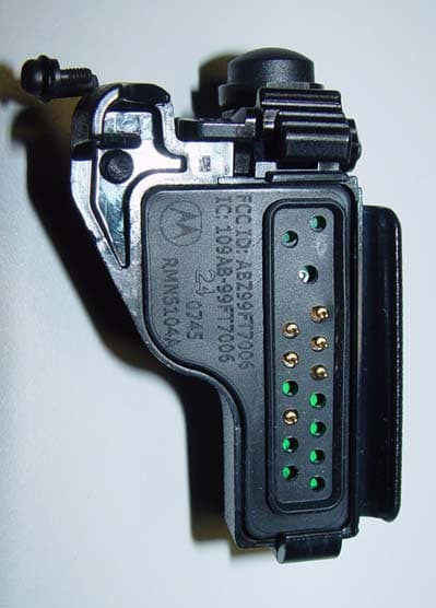
Click to zoom
Application Details
- Equipment Class
- DSS - Part 15 Spread Spectrum Transmitter
- Date of Grant
- Nov 19, 2007
- Application Purpose
- Original Equipment
- Date of Application
- Nov 19, 2007
- Equipment Note
- SPREAD SPECTRUM TRANSMITTER
- Frequency Range
- 2402.00000000 - 2480.00000000
- Company
- Motorola Solutions, Inc.
- Country
- United States
Documents & Files
Document Text
Text extracted from the exhibit documents filed with the FCC. Open a document above to read the original.
Users Manual
BLUETOOTH ® ADAPTER RMN5104 EN LAS BPFRC Wirelesssolution.book Page 1 Monday, November 5, 2007 8:48 PM Wirelesssolution.book Page 2 Monday, November 5, 2007 8:48 PM 1 English FOREWORD Product Safety and RF Exposure Compliance ATTENTION! The radio is restricted to occupational use only to satisfy FCC RF energy exposure requirements. Before using this product, read the RF energy awareness information and operating instructions in the Product Safety and RF Exposure booklet enclosed with your radio (Motorola Publication part number 6881095C98) to ensure compliance with RF energy exposure limits. This device complies with part 15 of the FCC Rules. Operation is subject to the following two conditions: (1)This device may not cause harmful interference, and (2)this device must accept any interference received, including interference that may cause undesired Any changes or modifications Before using this product, read the operating instructions for safe usage contained in the Product Safety and RF Exposure booklet enclosed with your radio. ! C a u t i o n Bluetooth® is a registered trademark of the Bluetooth Special Interest Group. Wirelesssolution.book Page 1 Monday, November 5, 2007 8:48 PM 2 English DESCRIPTION The RMN5104 Bluetooth Adapter is an accessory designed to complement Radio Models PR1500, XTS 1500, XTS 2500, XTS 5000 and HT1000. OPERATION Removing the Radio's Universal Connector Cover If the radio's universal connector cover is installed on the radio, refer to Figure 1 and perform the following steps: 1. Looking at the antenna side of the radio, insert a flat blade screwdriver between the lower end of the universal connector cover and the slot below the universal connector. 2. Pry upwards on the cover's lower end until it disengages from the radio. Figure 1: Removing the radio cover Wirelesssolution.book Page 2 Monday, November 5, 2007 8:48 PM 3 English Attaching the Bluetooth Adapter to the radio's Universal Connector Ensure that the radio is turned off before attaching the Bluetooth adapter to the radio. Refer to “Attaching the Bluetooth Adapter to the radio's Universal Connector” on page 3 and attach the adapter to the radio as follows: 1. Inspect the seal of the adapter to ensure that it is not damaged and is free of contamination. 2. Align the adapter to the radio's universal connector. 3. Looking at the antenna side of the radio, insert the bottom hooked end of the adapter into the bottom slot below the universal connector on the radio. 4. While holding the adapter seated in the bottom slot, pivot the top of the adapter towards the radio, then engage the adapter’s spring loaded latch in the radio's top slot. Wirelesssolution.book Page 3 Monday, November 5, 2007 8:48 PM 4 English 5. Secure the adapter to the radio using the tethered screw. Figure 2: Attaching the Bluetooth Adapter to the Radio’s Universal Connector To p Slot Bottom Slot Bottom Hooked End Screw Spring Latch Wirelesssolution.book Page 4 Monday, November 5, 2007 8:48 PM 5 English Pairing The Adapter And Headset 1. Turn ON the radio. 2. Place the headset in pairing mode (see headset manual). Place the adapter in pairing mode by pressing and holding the adapter PTT switch for 3 seconds (see Figure 3). Figure 3: The PTT Switch 3. Determine the adapter mode by observing the LED: • The LED blinks rapidly (ON twice per second) when the adapter is attempting to pair with the headset. • The LED blinks slowly (ON once per LED Indicator PTT Switch Wirelesssolution.book Page 5 Monday, November 5, 2007 8:48 PM 6 English second) when the adapter is attempting to reconnect with the previously paired headset. • The LED blinks very slowly (ON once every 4 seconds) when the adapter and headset are paired. 4. When the adapter and headset pair, the LED will light for 3 seconds and then blink once every 4 seconds thereafter. It is recommended to verify proper pairing by performing an audio check such as squelch or keypad tone. 5. If the adapter and headset fail to pair within 30 seconds (the LED continues to blink once per second), then turn them off and repeat Steps 1 to 3. 6. Once the adapter and headset are paired, received audio is routed to the headset. To transmit, press the adapter PTT switch and speak into the headset microphone. Reconnecting The Adapter and Headset 1. Turn ON the headset. 2. Attach the adapter to the radio. 3. Turn ON the radio. 4. The adapter and headset will automatically reconnect within 30 seconds. The LED will blink once every second during this time. When they reconnect, the LED will light for 3 seconds, then blink once every 4 seconds thereafter. Wirelesssolution.book Page 6 Monday, November 5, 2007 8:48 PM 7 English 5. If the adapter and headset do not reconnect within 30 seconds, then turn them off and follow the steps under “Pairing The Adapter And Headset” on page 5. Lost Bluetooth Link In the presence of interference, or if the radio and adapter are out of range of the paired headset, it is possible that the Bluetooth link between the adapter and headset may be dropped. In this case, received audio will be routed back to the radio, and the radio's microphone will be active. The adapter will attempt to reconnect to the headset for 15 seconds. After this time, to reestablish the Bluetooth link, it will be necessary to repeat the process of “Pairing The Adapter And Headset” on page 5. Wirelesssolution.book Page 7 Monday, November 5, 2007 8:48 PM 8 English Audio Routing Toggle Switch The toggle switch on top of the adapter allows the user to switch audio between the Bluetooth adapter and the radio. Figure 4: Audio Routing Toggle Switch • With the toggle switch positioned away from the radio, audio will be routed to the radio speaker, and the radio microphone is active during transmit. • With the toggle switch positioned towards the radio, audio will be routed to the Bluetooth headset ear piece, and the headset microphone will be active. The LED Indicator To g g l e Switch Wirelesssolution.book Page 8…
Text truncated - open the document above for the full version.
Block Diagram
FCC ID: ABZ99FT7006 / IC: 109AB-99FT7006 B LOCK DIAGRAM Bluetooth IC (BC31A223A) SW2 Analog/Digital Digital/Analog Converters 26 MHz Frequency Ref er enc e Bluetooth Controller and RF Transceiver Antenna Ma t c h Bandpass Filter Audio Input (+3.8 dBV) Audio Output (-42 dBV) Tx/Rx RF Signal (2.4 to 2.485 GHz 0 dBm Pout) 3.3 V Regulator DC Input (6-14 VDC) 3.3 VDC Accy. Select (TTL logic) SW1 Accy. PTT (TTL logic) 3.3 VDC LED Indicator Radio Accessory Port
Cover Letter(s)
FCC ID: ABZ99FT7006 Date: Sept 24, 2007 Authorization & Evaluation Division Federal Communications Commission Laboratory 7435 Oakland Mills Road Columbia, MD 21046 Subject: Application for Certification of Transmitter with FCC ID: ABZ99FT7006 Dear Sir or Madam: Motorola Inc., 1313 East Algonquin Road, Schaumburg, Illinois, herein submits application for Certification of a Part 15 Spread Spectrum Transmitter identified by FCC ID number ABZ99FT7006. Enclosed is a complete Certification Application. Please contact me if you require any additional information. Sincerely, /s/Larry D. Larsen(signed) Larry D. Larsen Engr. Sec Mgr. Tel: (847)-538-2239 Fax: (847)-538-4312 E-mail: [email protected]
External Photos
FCC ID: ABZ99FT7006 / IC: 109AB-99FT7006 EXTERNAL PHOTOS (Continued on next page.) RMN5104A FCC ID: ABZ99FT7006 / IC: 109AB-99FT7006 EXTERNAL PHOTOS (CONTINUED)
ID Label/Location Info
FCC ID: ABZ99FT7006 / IC: 109AB-99FT7006 FCC ID LABEL SAMPLE
Internal Photos
FCC ID: ABZ99FT7006 / IC: 109AB-99FT7006 INTERNAL PHOTOS
Test Report
FCC PART 15.247 AND IC RSS-210 TEST REPORT APPLICANT MOTOROLA, INC. 1301 EAST ALGONQUIN ROAD SCHAUMBURG IL 60196 USA FCC ID ABZ99FT7006 IC CERTIFICATION 109AB-99FT7006 MODEL NUMBER RMN5104A PRODUCT DESCRIPTION HANDSET BLUETOOTH DEVICE DATE SAMPLE RECEIVED 10/1/2007 DATE TESTED 10/15/2007 TESTED BY Richard Block APPROVED BY TIMCO REPORT NO. 3215AUT7TestReport.doc TEST RESULTS PASS FAIL THE ATTACHED REPORT SHALL NOT BE REPRODUCED EXCEPT IN FULL WITHOUT THE WRITTEN APPROVAL OF TIMCO ENGINEERING, INC. 849 NW STATE ROAD 45 NEWBERRY, FL 32669 USA PH: 888.472.2424 OR 352.472.5500 FAX: 352.472.2030 EMAIL: [email protected] HTTP://WWW.TIMCOENGR.COM APPLICANT: MOTORALA, INC. FCC ID: «GranteeCode»«EquipmentProductCode» REPORT #: W:\M\MOTOROLA_SCHAUMBURG_\3215AUT7\3215AUT7TestReport.doc Page 2 of 19 TABLE OF CONTENTS LETTER OF EXPLANATION.................................................. 3 EMC EQUIPMENT LIST...................................................... 4 TEST PROCEDURE......................................................... 5 POWER LINE CONDUCTED INTERFERENCE.................................. 6 NUMBER OF HOPPING CHANNELS........................................... 7 DWELL TIME OF A HOPPING CHANNEL...................................... 9 ANTENNA GAIN............................................................ 10 POWER OUTPUT........................................................... 11 FIELD STRENGTH OF SPURIOUS EMISSIONS................................ 12 RADIATED SPURIOUS EMISSIONS INTO ADJACENT RESTRICTED BAND...... 15 APPLICANT: MOTORALA, INC. FCC ID: «GranteeCode»«EquipmentProductCode» REPORT #: W:\M\MOTOROLA_SCHAUMBURG_\3215AUT7\3215AUT7TestReport.doc Page 3 of 19 LETTER OF EXPLANATION October 12, 2007 Federal Communications Commission Authorization and Evaluation Division 7435 Oakland Mills Road Columbia, MD 21046 SUBJECT: MOTOROLA, INC. FCC ID: ABZ To Whom It May Concern: The attached application is for a portable device that employs Bluetooth device. The unit employs an internal antenna. The antenna for the Bluetooth device has an antenna gain of +1.2 dBi. Should you have any questions or require any further information with regards to this, please feel free to contact me. Sincerely, Mario R. de Aranzeta C.E.T. Engineer MRD/sh Encl. APPLICANT: MOTORALA, INC. FCC ID: «GranteeCode»«EquipmentProductCode» REPORT #: W:\M\MOTOROLA_SCHAUMBURG_\3215AUT7\3215AUT7TestReport.doc Page 4 of 19 EMC EQUIPMENT LIST Device Manufacturer Model Serial Number Cal/Char Date Due Date 3/10-Meter OATS TEI N/A N/A Listed 3/20/07 3/19/10 3-Meter OATS TEI N/A N/A Listed 1/11/06 1/10/09 3-Meter Semi- Anechoic Chamber Panashield N/A N/A Listed 5/11/07 5/10/10 Antenna: Biconnical Eaton 94455-1 1057 CAL 12/12/05 12/12/07 Antenna: Biconnical Eaton 94455-1 1096 CAL 10/11/06 10/11/08 Analyzer Blue Tower Quasi-Peak Adapter HP 85650A 2811A01279 CAL 5/17/07 5/17/09 Analyzer Blue Tower RF Preselector HP 85685A 2926A00983 CAL 5/17/07 5/17/09 Analyzer Blue Tower Spectrum Analyzer HP 8568B 2928A04729 2848A18049 CAL 5/17/07 5/17/09 LISN Electro- Metrics ANS-25/2 2604 CAL 10/5/06 10/5/08 Antenna: Log- Periodic Electro- Metrics LPA-25 1122 CAL 12/1/06 12/1/08 APPLICANT: MOTORALA, INC. FCC ID: «GranteeCode»«EquipmentProductCode» REPORT #: W:\M\MOTOROLA_SCHAUMBURG_\3215AUT7\3215AUT7TestReport.doc Page 5 of 19 TEST PROCEDURE GENERAL: This report shall NOT be reproduced except in full without the written approval of TIMCO ENGINEERING, INC. POWER LINE CONDUCTED INTERFERENCE: The procedure used was ANSI standardC63.4- 2003 using a 50uH LISN. Both lines were observed with the UUT transmitting. The bandwidth of the spectrum analyzer was 10 kHz with an appropriate sweep speed. The ambient temperature of the UUT was 76°F with a humidity of 55%. BANDWIDTH 20 dB: The measurements were made with the spectrum analyzer's resolution bandwidth (RBW) = 1 MHz and the video bandwidth (VBW) = 3 MHz and the span set as shown on plot. POWER OUTPUT: The RF power output was measured at the antenna feed point using a peak power meter. ANTENNA CONDUCTED EMISSIONS: The RBW = 100 kHz, VBW = 300 kHz and the span set to 10.0 MHz and the spectrum was scanned from 30 MHz to the 10 th Harmonic of the fundamental. Above 1 GHz the resolution bandwidth was 1 MHz and the VBW = 3 MHz and the span to 50 MHz. RADIATION INTERFERENCE: The test procedure used was ANSI standard C63.4-2003 using an Agilent spectrum receiver with pre-selector. The bandwidth (RBW) of the spectrum receiver was 100 kHz up to 1 GHz and 1 MHz above 1 GHz with an appropriate sweep speed. The VBW above 1 GHz was 3 MHz. The analyzer was calibrated in dB above a microvolt at the output of the antenna. The ambient temperature of the UUT was 76°F with a humidity of 55%. APPLICANT: MOTORALA, INC. FCC ID: «GranteeCode»«EquipmentProductCode» REPORT #: W:\M\MOTOROLA_SCHAUMBURG_\3215AUT7\3215AUT7TestReport.doc Page 6 of 19 POWER LINE CONDUCTED INTERFERENCE RULES PART NO.: 15.107(a) REQUIREMENTS: QUASI-PEAK AVERAGE .15 – 0.5 MHz 66-56 dBuV 56-46 dBuV 0.5 – 5.0 56 46 5.0 – 30. 60 50 TEST PROCEDURE: ANSI C63.4-2003. The spectrum was scanned from .15 to 30 MHz. TEST DATA – Not applicable. APPLICANT: MOTORALA, INC. FCC ID: «GranteeCode»«EquipmentProductCode» REPORT #: W:\M\MOTOROLA_SCHAUMBURG_\3215AUT7\3215AUT7TestReport.doc Page 7 of 19 NUMBER OF HOPPING CHANNELS RULES PART NO.: 15.247(a)(1) TEST DATA: The number of hops is 79 hops NUMBER OF HOPPING CHANNELS APPLICANT: MOTORALA, INC. FCC ID: «GranteeCode»«EquipmentProductCode» REPORT #: W:\M\MOTOROLA_SCHAUMBURG_\3215AUT7\3215AUT7TestReport.doc Page 8 of 19 CHANNEL/CARRIER SPACING TEST DATA: The channel spacing is 1.03 MHz APPLICANT: MOTORALA, INC. FCC ID: «GranteeCode»«EquipmentProductCode» REPORT #: W:\M\MOTOROLA_SCHAUMBURG_\3215AUT7\3215AUT7TestReport.doc Page 9 of 19 DWELL TIME OF A HOPPING CHANNEL RULES PART NO.: 15.247(a)(1)(i) TEST DATA: The system makes the worst case at 1600 hopes per second, and 1 time slot has a length of 625us with 79 channels. A D…
Text truncated - open the document above for the full version.
Contact Information
Applicant
Matthew Nawrocki
Test Firm
MotorolaKenneth Weiss
Technical Specifications
| # | Rule Parts | Frequency Range | Power Output |
|---|---|---|---|
| 1 | 15C | 2.40 GHz - 2.48 GHz | 1.00 mW |
Other Applications from Motorola Solutions, Inc.

ABZ89FT4940
Aug 06, 2026Non Broadcast Transmitter
Equipment Class
TNB - Licensed Non-Broadcast Station TransmitterABZ89FT4950
Jun 25, 2026Non-Broadcast Transmitter
Equipment Class
TNB - Licensed Non-Broadcast Station TransmitterABZ89FT5901
Jun 20, 2024Non Broadcast Transmitter
Equipment Class
TNB - Licensed Non-Broadcast Station Transmitter
ABZ99FT5101B
May 02, 2023Non Broadcast Transmitter
Equipment Class
PCB - PCS Licensed Transmitter
ABZ99FT3095B
Mar 26, 2023Non Broadcast Transmitter
Equipment Class
TNB - Licensed Non-Broadcast Station Transmitter