ABZ99FT7010Office Talker
Motorola Solutions, Inc.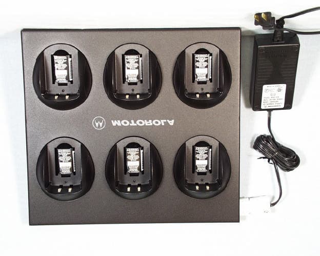
Click to zoom
Application Details
- Equipment Class
- PUE - Part 15 Unlicensed PCS portable Tx held to ear
- Date of Grant
- Mar 06, 2000
- Application Purpose
- Original Equipment
- Date of Application
- Dec 01, 1999
- Equipment Note
- Office Talker
- Frequency Range
- 1920.00000000 - 1930.00000000
- Company
- Motorola Solutions, Inc.
- Country
- United States
Documents & Files
Document Text
Text extracted from the exhibit documents filed with the FCC. Open a document above to read the original.
Users Manual
USER GUIDE 6880906Z36-O TC3000 ™ Portable Communicator and Motorola are registered trademarks of Motorola, Inc. TELARIO, TC3000, TR3000, and TS3000 are trademarks of Motorola, Inc. Copyright © 1999 Motorola, Inc. All rights reserved. This manual may not be reproduced, in whole or in part, in any form whatsoever, without the express written permission of Motorola, Inc. Note: The Motorola products described in this manual contain one or more computer programs. These computer programs are protected by copyright laws and international treaties. Unauthorized reproduction or distribution of these programs, or any part thereof, may result in severe civil and criminal penalties, and will be prosecuted to the maximum extent possible under the law. U.S. and international products patents pending. This product is covered by one or more issued U.S. Patents. Other Patent applications pending. 1 Introduction UTAM Registration ........................................................................................... 4 Inspection ......................................................................................................... 5 TC3000 Communicator Features ..................................................................... 6 Battery Installation Instructions ........................................................................ 9 To Insert Battery .......................................................................................... 9 To Remove Battery ...................................................................................... 9 Charging Instructions ..................................................................................... 10 Rapid Charge Method ............................................................................... 10 Slow Charge Method ................................................................................. 11 Attaching and Removing the Carry Holster .................................................... 12 Basic Functions Turning the TC3000 Communicator On.......................................................... 13 Turning the TC3000 Communicator Off.......................................................... 13 Setting the Volume ......................................................................................... 14 Audio Routing ................................................................................................. 14 Battery Life Indicator ...................................................................................... 14 Time-Out Timer .............................................................................................. 15 Idle Timer ....................................................................................................... 15 Menu Options ................................................................................................. 16 Select Ring Type........................................................................................ 16 Turning the TC3000 Communicator Off..................................................... 16 Phone Functions Entering Phone Service ................................................................................. 17 Making a Phone Call ...................................................................................... 17 Live Dial of a Phone Call ........................................................................... 17 Last Number Redial................................................................................... 18 Recall from Phone List .............................................................................. 18 Answering a Phone Call ................................................................................. 19 Hanging-Up a Phone Call............................................................................... 19 Holding a Phone Call...................................................................................... 19 Placing a Phone Call on Hold .................................................................... 19 Taking a Phone Call off Hold ..................................................................... 20 Transferring / Conferencing a Phone Call....................................................... 20 Phone Call Waiting ......................................................................................... 20 Voicemail ........................................................................................................ 20 Send Call / End Ring ...................................................................................... 21 Group Ringing ................................................................................................ 21 Table of Contents 2 Table of Contents Group Talk Selecting a Group........................................................................................... 22 Last Group Select / Displayed ................................................................... 22 Scroll.......................................................................................................... 22 Initiating a Group Talk..................................................................................... 23 Group Busy Signal ......................................................................................... 23 User Out of Range ......................................................................................... 24 System Busy Signal ....................................................................................... 24 Busy System Auto Retry ................................................................................ 25 Receiving a Group Talk .................................................................................. 26 Person Link Link ID Recognition ........................................................................................ 27 Entering Person Link Service ......................................................................... 27 Initiating a Person Link C…
Text truncated - open the document above for the full version.
Cover Letter(s)
COMMUNICATION CERTIFICATION LABORATORYTEST REPORT: 73-7045 FCC ID: ABZ99FT7010 Page 112 of 113 Exhibit 13 Exhibit 13: Cover Letters December 3, 1999 FEDERAL COMMUNICATIONS COMMISSION Equipment Authorization Division 7435 Oakland Mills Road Columbia, MD 21046 To Whom It May Concern: Enclosed is a FCC Part 15, Subpart D, Certification application for the Motorola, Inc. Model AAS19ZAN9121AA, FCC ID: ABZ99FT7010. Please let me know if I can be of further assistance. Sincerely yours, COMMUNICATION CERTIFICATION LABORATORY Joseph W. Jackson V.P. Marketing COMMUNICATION CERTIFICATION LABORATORYTEST REPORT: 73-7045 FCC ID: ABZ99FT7010 Page 113 of 113 Exhibit 13 Request for Confidentiality
External Photos
COMMUNICATION CERTIFICATION LABORATORYTEST REPORT: 73-7045 FCC ID: ABZ99FT7010 Page 4 of 114 Exhibit 3 Exhibit 3: Photographs of Overall Appearance Front View of the AAS19ZAN9121AA COMMUNICATION CERTIFICATION LABORATORYTEST REPORT: 73-7045 FCC ID: ABZ99FT7010 Page 5 of 114 Exhibit 3 Back View of the AAS19ZAN9121AA COMMUNICATION CERTIFICATION LABORATORYTEST REPORT: 73-7045 FCC ID: ABZ99FT7010 Page 6 of 114 Exhibit 3 Front View of the Single Charger COMMUNICATION CERTIFICATION LABORATORYTEST REPORT: 73-7045 FCC ID: ABZ99FT7010 Page 7 of 114 Exhibit 3 Bottom View of the Single Charger COMMUNICATION CERTIFICATION LABORATORYTEST REPORT: 73-7045 FCC ID: ABZ99FT7010 Page 8 of 114 Exhibit 3 Front View of the Multiple Charger COMMUNICATION CERTIFICATION LABORATORYTEST REPORT: 73-7045 FCC ID: ABZ99FT7010 Page 9 of 114 Exhibit 3 Back View of the Multiple Charger
ID Label/Location Info
COMMUNICATION CERTIFICATION LABORATORYTEST REPORT: 73-7045 FCC ID: ABZ99FT7010 Page 1 of 114 Exhibit 1 Exhibit 1: FCC ID Label Equipment Identification Label In accordance with the requirements of Sections 15.19 (a)(3), 15.311, 2.925 and 2.926 of the FCC Rules, the following information will be permanently affixed to the Motorola, Inc. Model AAS19ZAN9121AA. Shown below is the label and photograph showing where the label will be placed on the TC3000. TC3000 Label COMMUNICATION CERTIFICATION LABORATORYTEST REPORT: 73-7045 FCC ID: ABZ99FT7010 Page 2 of 114 Exhibit 1 Photograph Showing Label Placement
Internal Photos
COMMUNICATION CERTIFICATION LABORATORYTEST REPORT: 73-7045 FCC ID: ABZ99FT7010 Page 73 of 114 Exhibit 9 Exhibit 9: Internal Photographs Inside View of the AAS19ZAN9121AA COMMUNICATION CERTIFICATION LABORATORYTEST REPORT: 73-7045 FCC ID: ABZ99FT7010 Page 74 of 114 Exhibit 9 Component side of the interface board (Without RF Cans) COMMUNICATION CERTIFICATION LABORATORYTEST REPORT: 73-7045 FCC ID: ABZ99FT7010 Page 75 of 114 Exhibit 9 Solder side of the interface board (With RF Cans) COMMUNICATION CERTIFICATION LABORATORYTEST REPORT: 73-7045 FCC ID: ABZ99FT7010 Page 76 of 114 Exhibit 9 Solder side of the interface board (Without RF Cans)
RF Exposure Info
COMMUNICATION CERTIFICATION LABORATORYTEST REPORT: 73-7045 FCC ID: ABZ99FT7010 Page 78 of 113 Exhibit 11 Exhibit 11: RF Exposure/Environmental Evaluation Section 15.319 (i) Requirement: Unlicensed PCS devices are subject to the radiofrequency radiation exposure requirements specified in '' 1.1307(b), 2.1091 and 2.1093 of this chapter, as appropriate. All equipment shall be considered to operate in a “general population/uncontrolled” environment. Applications for equipment authorization of devices operating under this section must contain a statement confirming compliance with these requirements for both fundamental emissions and unwanted emissions. Technical information showing the basis for this statement must be submitted to the Commission upon request. Demonstration of Compliance: The AAS19ZAN9121AA is classified as a portable device. Therefore, the AAS19ZAN9121AA is subject to routine environmental evaluation for RF exposure as per ' 2.1093(c). Testing to demonstrate compliance to this section was performed by Motorola, Inc. and the results of this test is enclosed below. COMMUNICATION CERTIFICATION LABORATORYTEST REPORT: 73-7045 FCC ID: ABZ99FT7010 Page 79 of 113 Exhibit 11 COMMERCIAL, GOVERNMENT, AND INDUSTRIAL SOLUTION SECTOR (CGISS) ELECTROMAGNETIC EXPOSURE (EME) TESTING LABORATORY SAR TEST REPORT October 6, 1999 Prepared by Jim Fortier, Lead Engineer COMMUNICATION CERTIFICATION LABORATORYTEST REPORT: 73-7045 FCC ID: ABZ99FT7010 Page 80 of 113 Exhibit 11 1.0 Environmental Evaluation for Occupational RF Exposure -- Pursuant 47 CR2.1093(d)(2) 1.1 General Information FCC ID: ABZ99FT7010 Device category: Portable radio RF exposure environment: Uncontrolled Test method: Measurement Note: The test software operation utilized 2 time slots (2/8 or 25% duty cycle), therefore the measured SAR results must be divided by 2 to simulate the proper user mode (1/8 slots or 12.5% duty cycle). Special Note: This is a very low RF power radio typically operating in the 33 mW range (conducted). The resulting measured SAR was below the 10 micro-Watt/g sensitivity limit of the test system. Therefore, the resulting SAR scan plots are very erratic due to being in the system noise level and therefore it can be concluded that these results demonstrate that the SAR levels are well within the FCC limit of 1.6 W/kg, per the requirements of 47 CFR 2.1093(d)(2). 1.2 Antenna Description Antenna type: monople ( ) dipole ( ) Helix ( x ) Patch ( ) Other ( ) 1/4 wave Antenna Location on Device: Left ( ) Right ( x ) Top ( x ) Bottom ( ) Front ( ) Back ( ) Antenna Dimensions: Length (extended) 1.8 cm Diameter (at tip of antenna) 1.05 cm Diameter (at middle of antenna) 1.15 cm Diameter (at base of antenna) 1.25 cm Antenna configuration: Fixed (x) Retractable ( ) External ( ) Other ( ) Antenna Gain: -1 (dBi) 1.3 Test Signal Test signal source: Test mode ( x ) Base Station ( ) Simulator ( ) Other ( ) Signal Modulation: C.W. ( ) TDMA ( x ) Other ( ) COMMUNICATION CERTIFICATION LABORATORYTEST REPORT: 73-7045 FCC ID: ABZ99FT7010 Page 81 of 113 Exhibit 11 1.4 Output Power Output power measurement conditions: Free Space radiated ( ) SAR test configuration ( ) Conducted ( x ) Output power measured with: Power meter (x ) Base Station Simulator ( ) Spectrum Analyzer ( ) Measured Output Power before and after SAR runs Measurements made with the radio operating with 2/8 multiplexing (25% duty cycle) Output Power Measured at Frequency (MHz) Output Power Measured Before SAR with Fully Charged Battery (mWatts) Output Power Measured After SAR (mWatts) 1920.053734 after 20 mins 1925.154036 after 20 mins 1930.254036 after 20 mins No battery changes made during SAR runs 1.5 Test Position The following describes the three test positions used to perform SAR measurements on the portable radio: 1. Head - The portable radio is positioned in a normal operating position by aligning the axis of the radio with a line from the center of the ear to the corner of the lips, center the listening area of the radio over the ear canal. Next, position the radio as close as possible to the phantom, preferably with three points of contact with the phantom to allow for best coupling to the simulated tissue. 2. Face - The portable radio is positioned in the right hand of a full body phantom and the radio’s normal speaking area is aligned with the center of the phantom’s mouth. 3. Abdomen - The portable radio is positioned in a carry case accessory with belt clip beneath the abdomen of the full body phantom with the back of the radio facing the abdomen, the keypad/display facing the floor and the antenna is made to be as parallel as possible to the phantom. Reference figures: 1, 2, and 3 for portable radio antenna orientation and distances relative to phantoms. COMMUNICATION CERTIFICATION LABORATORYTEST REPORT: 73-7045 FCC ID: ABZ99FT7010 Page 82 of 113 Exhibit 11 1.6 Measurement Uncertainty The table below list an estimate of the possible errors that are associated with the measurement system. Error (%)Distributio n Divisor Standard Uncertainty Measurement of the conductivity of tissue simulated +/- 3 Normal 21.5 Temperature rise calibration of probe+/- 5Rectangular1.7322.89 Measurement of thermal capacity of tissue simulated +/- 5Normal22.5 Accuracy of a repeatable radio position+/- 1Normal20.5 Probe isotropic response +/- 12 Normal26 With a coverage factor of k=2, providing a level of confidence of approximately 95%, the Uncertainty for SAR testing is ± 14.6%. 1.7 Measurement System and Phantom Description Description of Measurement System and Performance: The measurement system used to evaluate the portable radio SAR consist of a small diameter isotropic electric field probe, multiple axis probe positioning system, differential amplifiers, high impedance cables connecting the probes to the differential amplifiers and the amplifier output to a computer, IDX FLEXWARE software version 3.58, robotics arm with its extension, a custom probe holder, and supportin…
Text truncated - open the document above for the full version.
Test Report
COMMUNICATION CERTIFICATION LABORATORYTEST REPORT: 73-7045 FCC ID: ABZ99FT7010 Page 12 of 114 Exhibit 6 Exhibit 6: Test Report TEST REPORT FROM: COMMUNICATION CERTIFICATION LABORATORY 1940 W. Alexander Street Salt Lake City, Utah 84119-2039 Type of Report: Certification TEST OF: AAS19ZAN9121AA AAS19ZAN9121AANC FCC ID: ABZ99FT7010 To Part 15 Subpart D of the FCC Rules and Regulations Test Report Serial No: 73-7045 Applicant: Motorola, Inc. 5201 Tollview Drive Rolling Meadows, IL 60008 Date(s) of Test: August 26 – November 11, 1999 Issue Date: December 3, 1999 Equipment Receipt Date: August 25, 1999 COMMUNICATION CERTIFICATION LABORATORYTEST REPORT: 73-7045 FCC ID: ABZ99FT7010 Page 13 of 114 Exhibit 6 CERTIFICATION OF ENGINEERING REPORT This report has been prepared by Communication Certification Laboratory to evaluate the device described below with the requirements of FCC Part 15, Subpart D. Specific identifying information for the device tested is given below. -ApplicantMotorola, Inc. 5201 Tollview Drive Rolling Meadows, IL 60008 -Manufacturer:Motorola, Inc. 1411 East Washington Mt. Pleasant, IA 52641 -Trade Name:TELARIO TM TC3000 -Model Number:AAS19ZAN9121AA and AAS19ZAN9121AANC -FCC ID Number:ABZ99FT7010 On this 3 rd day of December 1999, I, individually, and for Communication Certification Laboratory, certify that the statements made in this engineering report are true, complete, and correct to the best of my knowledge, and are made in good faith. COMMUNICATION CERTIFICATION LABORATORY Checked by: William S. Hurst, P.E. Vice President Tested by: Roger J. Midgley EMC Engineering Manager COMMUNICATION CERTIFICATION LABORATORYTEST REPORT: 73-7045 FCC ID: ABZ99FT7010 Page 14 of 114 Exhibit 6 SECTION 1 GENERAL INFORMATION 1.1 Product Description The AAS19ZAN9121AA is the handset (TC3000) portion of a wireless system (see Theory of Operation in Exhibit 12). The TC3000 is sold under two different model numbers, both units are electrically identical the only difference is one is sold with a battery charger and one is sold without the battery charger. The model for the unit with the charger is AAS19ZAN9121AA and the model for the unit without the charger is AAS19ZAN9121AANC. This application is for the handset (TC3000), which is identified by FCC ID: ABZ99FT7010. There is a second handset (TR3000), which is identified by FCC ID: ABZ99FT7011 and a base station (TS3000), which is identified by FCC ID: ABZ99FT7012. Both these applications are being submitted concurrently with this application. 1.2 Test Specification The AAS19ZAN9121AA is an Isochronous device that operates in the 1920-1930 MHz sub-band; therefore the AAS19ZAN9121AA is subject to the provisions of FCC Part 15, Subpart D. Unlicensed Personal Communications Service Devices. 1.3 Test Methods & Procedures The AAS19ZAN9121AA was tested in accordance with ANSI C63.17-1998. COMMUNICATION CERTIFICATION LABORATORYTEST REPORT: 73-7045 FCC ID: ABZ99FT7010 Page 15 of 114 Exhibit 6 SECTION 2. SUMMARY OF TEST RESULTS: 2.1 Summary of Tests: FCC Section Description Report Section ANSI C63.17 Section Result 15.307 Affidavit from UTAM, Inc. certifying participation in UTAM, Inc. 3.2.1N/AComplies 15.309Cross Reference to Subpart B 3.2.26.1.6.3Complies 15.311Labelling Requirements 3.2.3N/AComplies 15.315AC power line conducted limits 3.2.4N/AComplies 15.317Antenna requirement3.2.5N/AComplies 15.319 (a)Frequency of operation 3.2.6N/AComplies 15.319 (b)Modulation technique 3.2.76.1.4Complies 15.319 (c)Peak transmit power and emission bandwidth 3.2.86.1.2Complies 15.319 (d)Power spectral density 3.2.96.1.5Complies 15.319 (e)Directional gain of antenna 3.2.10N/AComplies 15.319 (f)Automatic discontinuance of transmission 3.2.11N/AComplies 15.319 (i)IEEE C95.1-1991 and IEEE C95.3-1991 3.2.12N/AComplies 15.323 (a)Channel allocation3.2.13N/AComplies COMMUNICATION CERTIFICATION LABORATORYTEST REPORT: 73-7045 FCC ID: ABZ99FT7010 Page 16 of 114 Exhibit 6 FCC Section Description Report Section ANSI C63.17 Section Result 15.323 (b)Channel packing3.2.148.1.2Complies 15.232 (c)Time and Spectrum monitoring 3.2.15Sections 7 and 8 Complies 15.323 (c)(1) Transmit window monitoring 3.2.167.3.2.2 and 7.5 Complies 15.323 (c)(2) Monitoring threshold 3.2.177.3.2.1Complies 15.323 (c)(3) Transmission duration 3.2.18N/AComplies 15.323 (c)(4) Acknowledgments3.2.198.2.1Complies 15.323 (c)(5) Least interfered channel 3.2.207.3.2.1, 7.3.2.2 and 8.2.1 Complies 15.323 (c)(6) Random waiting interval 3.2.218.1.3Complies 15.323 (c)(7) Threshold monitoring bandwidth, Threshold monitoring reaction time 3.2.227.4 and 7.5 Complies 15.323 (c)(8) Threshold monitoring antenna 3.2.23N/AComplies 15.323 (c)(9) Monitoring threshold relaxation 3.2.24N/AComplies 15.323 (c)(10) Duplex connections3.2.258.2.3Complies 15.323 (c)(11) Alternative monitoring interval 3.2.268.2.4Complies 15.323 (c)(12) Limitation on use of Section (c)(10) or (c)(11) 3.2.27N/AComplies COMMUNICATION CERTIFICATION LABORATORYTEST REPORT: 73-7045 FCC ID: ABZ99FT7010 Page 17 of 114 Exhibit 6 FCC Section Description Report Section ANSI C63.17 Section Result 15.323 (d)Spurious emissions3.2.286.1.6Complies 15.323 (e)Frame repetition stability / frame period and jitter 3.2.296.2.3 and 6.2.4 Complies 15.323 (f)Frequency stability3.2.306.2.2Complies COMMUNICATION CERTIFICATION LABORATORYTEST REPORT: 73-7045 FCC ID: ABZ99FT7010 Page 18 of 114 Exhibit 6 SECTION 3. MEASUREMENTS, EXAMINATIONS AND DERIVED RESULTS: 3.1 General Comments This section contains the test results only. Details of the test methods used, etc., can be found in Appendix A of this report. 3.2 Test Results 3.2.1 Coordination with fixed microwave service § 15.307 Measurement Data: The affidavit from UTAM, Inc. is enclosed in Exhibit 12. 3.2.2 Cross Reference to Subpart B § 15.309 The requirements of Subpart D apply only to the radio transmitter contained in the PCS device. Other aspects of the operation of a PCS device may be subject to requirements contained elsewhere…
Text truncated - open the document above for the full version.
Test Setup Photos
COMMUNICATION CERTIFICATION LABORATORYTEST REPORT: 73-7045 FCC ID: ABZ99FT7010 Page 70 of 114 Exhibit 7 Exhibit 7: Test Set-Up Photographs Front View of Worst Case Radiated and Line Conducted Emissions Test Set-up COMMUNICATION CERTIFICATION LABORATORYTEST REPORT: 73-7045 FCC ID: ABZ99FT7010 Page 71 of 114 Exhibit 7 Back View of Worst Case Radiated and Line Conducted Emissions Test Set-up
Contact Information
Applicant
Matthew Nawrocki
Technical Contact
Communication Certification LaboratoryRoger J Midgley
[email protected](801) 972-6146
1940 W. Alexander Street · Salt Lake City, Utah · United States
Test Firm
Communication Certification Lab.Scott Earl
Technical Specifications
| # | Rule Parts | Frequency Range | Power Output | Emission | Tolerance |
|---|---|---|---|---|---|
| 1 | 15D | 1.92 GHz - 1.93 GHz | 40.00 mW | F1E | 10.0000000000 ppm |
Other Applications from Motorola Solutions, Inc.

ABZ89FT4940
Aug 06, 2026Non Broadcast Transmitter
Equipment Class
TNB - Licensed Non-Broadcast Station TransmitterABZ89FT4950
Jun 25, 2026Non-Broadcast Transmitter
Equipment Class
TNB - Licensed Non-Broadcast Station TransmitterABZ89FT5901
Jun 20, 2024Non Broadcast Transmitter
Equipment Class
TNB - Licensed Non-Broadcast Station Transmitter
ABZ99FT5101B
May 02, 2023Non Broadcast Transmitter
Equipment Class
PCB - PCS Licensed Transmitter
ABZ99FT3095B
Mar 26, 2023Non Broadcast Transmitter
Equipment Class
TNB - Licensed Non-Broadcast Station Transmitter