ABZ99FT7013Part 15 Transmitter
Motorola Solutions, Inc.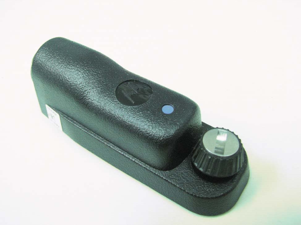
Click to zoom
Application Details
- Equipment Class
- DCD - Part 15 Low Power Transmitter Below 1705 kHz
- Date of Grant
- Dec 26, 2011
- Application Purpose
- Original Equipment
- Date of Application
- Dec 26, 2011
- Equipment Note
- Part 15 Transmitter
- Frequency Range
- 0.12500000 - 0.12500000
- Company
- Motorola Solutions, Inc.
- Country
- United States
Documents & Files
Document Text
Text extracted from the exhibit documents filed with the FCC. Open a document above to read the original.
Users Manual
Operations Critical Wireless Adapter with Touch Pairing, FM PMLN5993 Blank.fm Page 1 Wednesday, October 13, 2010 9:34 PM i English FOREWORD Product Safety and RF Exposure Compliance ATTENTION! The radio is restricted to occupational use only to satisfy ICNIRP/ FCC RF energy exposure requirements. Before using this product, read the RF energy awareness information and operating instructions in the Product Safety and RF Exposure booklet enclosed with your radio (Motorola Publication part number 6881095C98 - This is US Safety. EMEA version is 6864117B25.) to ensure compliance with RF energy exposure limits. This device complies with part 15 of the FCC Rules. Operation is subject to the following two conditions: (1) This device may not cause harmful interference, and (2) this device must accept any interference received, including interference that may cause undesired operation. Any changes or modifications not expressly approved by Motorola may void the user's authority to operate this device. Before using this product, read the operating instructions for safe usage contained in the Product Safety and RF Exposure booklet enclosed with your radio. ! C a u t i o n 1 English DESCRIPTION The PMLN5993 Operations Critical Wireless Adapter with Touch Pairing, FM is an accessory designed for MOTOTRBO radios with radio software version R01.07.00 or later. OPERATION Attaching the Wireless Adapter to the Radio's Universal Connector Below are the steps to attach the Wireless Adapter PMLN5993 to the radio’s universal connector: 1. Ensure that the radio is turned off before attaching the adapter to the radio. 2. If attached to the radio, remove the universal connector cover from the side of the radio. 3. Attach the Wireless Adapter by hooking it on the radio and securing it with the thumb screw. (See Figure 1). 4. The Wireless Adapter is ready for use. Figure 1 Wireless Adapter Wireless Adapter Hook Thumb Screw Universal Connector 2 English Supported Wireless Devices • Wireless Accessory Kit, Near Field Pairing, 12" cable • Wireless Accessory Kit, Near Field Pairing, 9.5" cable • Wireless Accessory Kit, Near Field Pairing Please refer to the link below for kits offered in each region. • www.motorolasolutions.com/mototrbo 3 English LED Status Indication State LED Indication Successful Power Up Blue LED Blinks 3 times Not Paired with any Wireless Device Blue LED Blinking Paired but Not Connected with Wireless Device Blue LED Illuminated Wireless Device Connected Blue LED Heartbeat Blinking (On for every 4 seconds) Adapter in Dark Mode Blue LED OFF Table 1: LED Status Indication 4 English Wireless Adapter Pairing Procedure 1. Place the wireless device in pairing mode. Refer to respective wireless device’s user manual. 2. Refer to “Attaching the Wireless Adapter to the Radio's Universal Connector” on page 1 to attach the adapter to the radio. 3. Place the blue dot (secure pairing spot) on the wireless device within one inch of the blue dot (secure pairing spot) on the adapter. a.The adapter allows a maximum of one wireless audio device and one wireless PTT device to pair with it. b.If the maximum number of device is reached, the user needs to unpair the device. Refer to “Unpairing Or Replacing With New Wireless Device” on page 5 for unpairing procedure. Note: If the user wish to replace a new wireless device, the user needs to erase the existing pairing info. Refer to “Unpairing Or Replacing With New Wireless Device” on page 5 for unpairing procedure. Figure 2 PTT Button and LED on the Wireless Adapter 4. The adapter provides LED indication when successfully connected with the wireless device. The radio will generate a link established Tone on the radio speaker whenever a Wireless Audio Device is connected. Refer to “LED Status Indication” on page 3. PTT Button LED 5 English 5. Wireless devices which connected with the adapter will be automatically reconnected on the next power up. Unpairing Or Replacing With New Wireless Device a.Power OFF the Radio b.Press and hold the PTT button on the adapter while powering up the radio until the adapter provides LED indication. This indicates that the adapter has unpaired with the previously paired device(s) and is ready to pair with the new device. Refer to “LED Status Indication” on page 3. c. Repeat steps 1 to 5 to pair a new wireless device. Note: When this step is performed, it will erase all the previously paired device information. However, the user can repeat the “Wireless Adapter Pairing Procedure” on page 4 for pairing with intended device. Wireless Link Lost In the event of interference, or if the wireless device is out of range, the link between the Wireless Adapter and wireless device may be lost. If the link between the adapter and wireless audio device is lost, the radio will generate a link lost tone and the received audio is automatically routed back to the radio’s speaker and the radio will generate a Bad Key Tone whenever the PTT button on the adapter or the connected wireless PTT device is pressed. 6 English Wireless Link Restored Once the wireless device is in range or after interference has subsided, the link between the Wireless Adapter and the wireless device is restored. When the link between the adapter and the wireless audio device is restored, the radio will generate a link established tone and the adapter will allow the PTT button on the adapter and the connected wireless device(s) to key-up the radio. Dark Mode Dark Mode allows the Wireless Adapter to turn off the Blue LED when triggered by the last connected wireless device. • The adapter's LED will display normal LED indication while radio is powering on or until connected with a wireless device. • Upon connection establishment with the last connected wireless device, the adapter's LED mode will be synchronized with that device's Blue LED mode. • The adapter's LED mode will synchronize with a connected wireless device's Blue LED mode if the user toggles IN and OUT of Dark Mode on that wir…
Text truncated - open the document above for the full version.
External Photos
FCC ID:ABZ99FT7013 / IC:109AB‐99FT7013 EXTERNAL PHOTOS FCC ID:ABZ99FT7013 / IC:109AB‐99FT7013 EXTERNAL PHOTOS FCC ID:ABZ99FT7013 / IC:109AB‐99FT7013 EXTERNAL PHOTOS
ID Label/Location Info
FCC ID:ABZ99FT7013 / IC:109AB‐99FT7013 FCC ID Label Samples
Internal Photos
FCC ID:ABZ99FT7013 / IC:109AB‐99FT7013 INTERNAL PHOTOS FCC ID:ABZ99FT7013 / IC:109AB‐99FT7013 INTERNAL PHOTOS
Test Report
Engineering Test Report No. 1103036-02 Measurement of RF Emissions from a PMLN5993A Wireless Dongle Transmitter For Motorola Solutions 1301 E. Algonquin Road Schaumburg, IL 60196 P.O. Number NP5404217 Date Tested October 10, 2011 Test Personnel Richard E. King Test Specification FCC "Code of Federal Regulations” Title 47 Part15, Subpart C, 15.209 Industry Canada RSS-Gen Test Report By: Richard E. King EMC Engineer Requested By: Larry Larsen Motorola Solutions Approved By: Raymond J. Klouda Registered Professional Engineer of Illinois - 44894 Elite Electronic Engineering, Inc. 1516 Centre Circle Downers Grove, IL 60515 Tel : (630) 495-9770 Fax: (630) 495-9785 www.elitetest.com Engineering Test Report No. 1103036-02 TABLE OF CONTENTS PARAGRAPH DESCRIPTION OF CONTENTS PAGE NO. THIS REPORT SHALL NOT BE REPRODUCED, EXCEPT IN FULL, WITHOUT THE WRITTEN APPROVAL OF ELITE ELECTRONIC ENGINEERING INCORPORATED. Page 2 of 14 1. Introduction ................................................................................................................................................... 4 1.1. Scope of Tests ..................................................................................................................................... 4 1.2. Purpose ............................................................................................................................................... 4 1.3. Deviations, Additions and Exclusions .................................................................................................. 4 1.4. EMC Laboratory Identification ............................................................................................................. 4 1.5. Laboratory Conditions.......................................................................................................................... 4 2. Applicable Documents .................................................................................................................................. 4 3. EUT Setup and Operation ............................................................................................................................ 4 3.1. General Description ............................................................................................................................. 4 3.1.1. Power Input ................................................................................................................................. 5 3.1.2. Peripheral Equipment ................................................................................................................. 5 3.1.3. Signal Input/Output Leads .......................................................................................................... 5 3.1.4. Grounding ................................................................................................................................... 5 3.2. Operational Mode ................................................................................................................................ 5 3.3. EUT Modifications ................................................................................................................................ 5 4. Test Facility and Test Instrumentation ......................................................................................................... 5 4.1. Shielded Enclosure .............................................................................................................................. 5 4.2. Test Instrumentation ............................................................................................................................ 5 4.3. Calibration Traceability ........................................................................................................................ 5 4.4. Measurement Uncertainty ................................................................................................................... 5 5. Test Procedures ........................................................................................................................................... 6 5.1. Powerline Conducted Emissions ......................................................................................................... 6 5.1.1. Requirements .............................................................................................................................. 6 5.2. Radiated Measurements ..................................................................................................................... 6 5.2.1. Requirements .............................................................................................................................. 6 5.2.2. Procedures .................................................................................................................................. 6 5.2.3. Results ........................................................................................................................................ 7 6. Other Test Conditions .................................................................................................................................. 7 6.1. Test Personnel and Witnesses ............................................................................................................ 7 6.2. Disposition of the EUT ......................................................................................................................... 7 7. Conclusions .................................................................................................................................................. 7 8. Certification................................................................................................................................................... 8 9. Equipment List .............................................................................................................................................. 9 Engineering Test Report No. 1103036…
Text truncated - open the document above for the full version.
Test Setup Photos
Engineering Test Report No. 1103036-02 Page 11 of 14 Figure 2 Test Setup for Radiated Emissions, 10kHz to 30MHz – Horizontal Polarization Test Setup for Radiated Emissions, 10kHz to 30MHz – Vertical Polarization
Contact Information
Applicant
Matthew Nawrocki
Test Firm
Elite Electronic Engineering Inc.Kevin Halpin
Technical Specifications
| # | Rule Parts | Frequency Range | Power Output |
|---|---|---|---|
| 1 | 15C | 0.125 MHz - 0.125 MHz | - |
Other Applications from Motorola Solutions, Inc.

ABZ89FT4940
Aug 06, 2026Non Broadcast Transmitter
Equipment Class
TNB - Licensed Non-Broadcast Station TransmitterABZ89FT4950
Jun 25, 2026Non-Broadcast Transmitter
Equipment Class
TNB - Licensed Non-Broadcast Station TransmitterABZ89FT5901
Jun 20, 2024Non Broadcast Transmitter
Equipment Class
TNB - Licensed Non-Broadcast Station Transmitter
ABZ99FT5101B
May 02, 2023Non Broadcast Transmitter
Equipment Class
PCB - PCS Licensed Transmitter
ABZ99FT3095B
Mar 26, 2023Non Broadcast Transmitter
Equipment Class
TNB - Licensed Non-Broadcast Station Transmitter