ABZ99FT7014Part 15 Transmitter
Motorola Solutions, Inc.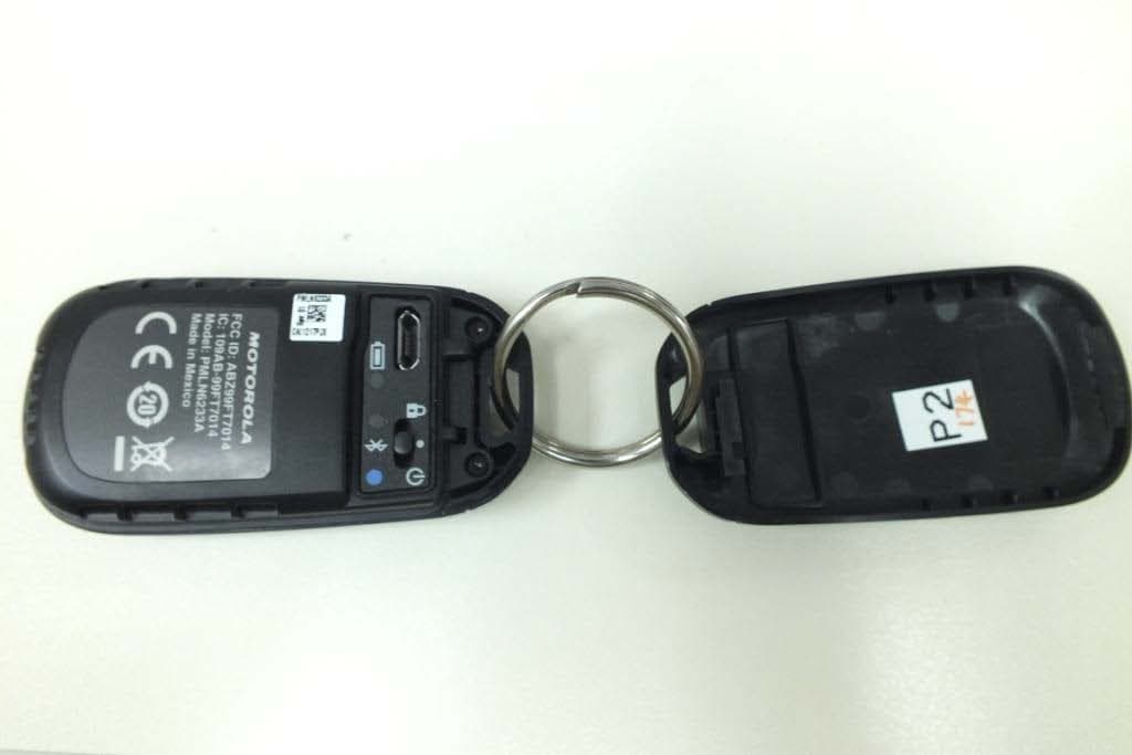
Click to zoom
Application Details
- Equipment Class
- DCD - Part 15 Low Power Transmitter Below 1705 kHz
- Date of Grant
- Nov 28, 2012
- Application Purpose
- Original Equipment
- Date of Application
- Nov 28, 2012
- Equipment Note
- Part 15 Transmitter
- Frequency Range
- 0.12500000 - 0.12500000
- Company
- Motorola Solutions, Inc.
- Country
- United States
Documents & Files
Document Text
Text extracted from the exhibit documents filed with the FCC. Open a document above to read the original.
Users Manual
m Trunk Button/ Prog 5 Prog 2 Prog 1 Prog 3 Prog 4 Panic Button/ Prog 6 KEY FOB OVERVIEW Mission Critical Wireless RCU Key Fob PMLN6233 *68012007013* 68012007013-B EN MOTOROLA, MOTO, MOTOROLA SOLUTIONS and the Stylized M logo are trademarks or registered trademarks of Motorola Trademark Holdings, LLC and are used under license. All other trademarks are the property of their respective owners. © 2012 Motorola Solutions, Inc. All rights reserved. FOREWORD Product Safety and RF Exposure Compliance ATTENTION! The radio is restricted to occupational use only to satisfy ICNIRP/FCC RF energy exposure requirements. Before using this product, read the RF energy awareness information and operating instructions in the Product Safety and RF Exposure booklet enclosed with your radio (Motorola Publication part number 6881095C98 (US) or 6864117B25 (EMEA)) to ensure compliance with RF energy exposure limits. This device complies with part 15 of the FCC Rules and Industry Canada licence-exempt RSS standard(s). Operation is subject to the following two conditions: (1) this device may not cause interference, and (2) this device must accept any interference, including interference that may cause undesired operation of the device. Le présent appareil est conforme aux CNR d’Industrie Canada applicables aux appareils radio exempts de licence. L’exploitation est autorisée aux deux conditions suivantes: (1) I’appareil ne doit pas produire de brouillage, et (2) I’utilisateur de I’appareil doit accepter tout brouillage radioélectrique subi, même si le brouillage est susceptible d’en compromettre le fonctionnement. Any changes or modifications not expressly approved by Motorola may void the user’s authority to operate this device. Battery Information: Battery is shipped with a nominal charge between 30% and 50%. Battery should be stored between -10 °C (14 °F) and 30 °C (86 °F) to minimize permanent capacity loss. Caution: Storing your fully charged accessory in high-temperature conditions may permanently reduce the life of the internal battery. Note: The battery is not a user replaceable part. Before using this product, read the operating instructions for safe usage contained in the Product Safety and RF Exposure booklet enclosed with your radio. Caution Important Information: •Do not charge your accessory in temperatures below 0 °C (32 °F) or above 45 °C (113 °F). Do not store your accessory in direct sunlight or where expected temperatures can exceed this range such as inside a parked car. •Storing your fully charged accessory in high-temperature conditions may permanently reduce the life of the internal battery. •Battery life may temporarily shorten in low-temperature conditions. INTRODUCTION The PMLN6233 Mission Critical Wireless RCU Key Fob is compatible with APX 2000, 3000, 4000, 5000, 6000, 7000 radios with firmware SR7.13 and above. Refer to the APX radio’s user manual for approved body-worn accessories. CAP OPENING/CLOSING 1 a b 2 Flip Open 3 Micro USB Jack and Charger Battery Status Indicator Keypad Lock Position Blue Dot Power ON/OFF Pairing Indicator Keypad Unlock Position INTERNAL FEATURE LAYOUT StateLED Indication 90% CHARGING YOUR KEY FOB Charge key fob 3 hours before using. POWERING OFF KEY FOB Slide and hold 3 sec POWERING ON KEY FOB Slide and hold 3 sec PAIRING YOUR KEY FOB First time connection steps: 1. Verify that both the radio and the key fob are powered ON and in pairing mode. 2.To enter pairing mode on the key fob, press and hold the Trunk button while powering up the key fob. 3.Place the Blue Dot (touch pairing spot) of the key fob on the Blue Dot on the radio. 4.Wireless Link Connected with radio indication is provided upon successful link establishment (refer to Subsequent Connection table). 5.Your key fob is now ready to be used. 1 cm SUBSEQUENT CONNECTION Same Radio: If the Bluetooth link is lost, connection will be automatically re-established when the radio and key fob come within range. The minimum line-of-sight range for the key fob is 30 feet. However, the body tends to obstruct the signal, therefore the normal usage range is 6 feet around your body. New Radio: Put the key fob in Pairing Mode by powering ON while pressing Trunk button simultaneously. Follow steps from Pairing Your Key Fob. StateLED Indication Not Paired Paired Successfully Wireless Link Connected with Radio Wireless Link Disconnected from Radio 2 sec 100 ms 1000 ms 50 ms4000 ms PROGRAMMABLE BUTTON CONTROL Refer radio CPS for button assignment. Once the key fob connects with the Radio, the Programmable Button will operate as defined in the radio CPS setting. SURVEILLANCE MODE (DARK MODE) After Connection with the Radio, if the Radio is in the Surveillance Mode the key fob shall also enter Surveillance Mode. •The key fob will display LED indication before it gets Connected to the Radio and will enter Surveillance Mode 20 seconds after connection is established. •The key fob will not show LED indication on Link Lost if Radio is in Surveillance Mode. 1. Enable2. Only the PTT and the Volume Up/Down functionality remain functional during feature lock. 3. Disable FEATURE LOCK BATTERY ALERTS ERROR INDICATOR TROUBLESHOOTING If at any time the wireless connection cannot be re-established, or the key fob is operating incorrectly: 1.Power Cycle the key fob and the radio. The connection should re-establish. 2.If the problem continues; Refer to Pairing Your Key Fob to repeat the connection process. StateLED Indication Remaining Battery Life 3% 10% 200 ms 100 ms 4000 ms 50 ms 5 min 30 min Error REPLACEMENT PART The following replacement part is available for the PMLN6233 Mission Critical Wireless RCU Key Fob: Please contact your local Motorola Representative or Dealer for details. Part NumberDescription PMLN6475_ASSY, BACK COVER SOFTWARE UPGRADES Please go to the respective regional MOL links below: 1.EMEA - https://emeaonline.motorola.com 2.LACR/NA - https://motonline.mot.com 3.APAC - https://asiaonline.mot.com OPEN SOURCE SOFT…
Text truncated - open the document above for the full version.
Cover Letter(s)
FCC ID: ABZ99FT7014 EXHIBIT 13B SHEET 1 REQUEST FOR CONFIDENTIALITY Date: Sept 3 rd , 2012 Office of Engineering and Technology Laboratory Division Equipment Authorization Branch FCC Laboratory 7435 Oakland Mills Road Columbia, MD 21046 Subject: Request for Confidentiality for Transmitter with FCC ID: ABZ99FT7014 Dear Sir / Madam, Motorola Solutions is requesting that Exhibit 4 (Circuit Descriptions), Exhibit 5 (Schematic Diagrams) and Exhibit 10 (Parts List) not be made routinely available for public inspection. Motorola considers the information in these exhibits to be classified as trade secrets, pursuant to 47 CFR Section 0.457(d), 0.459 and Section 552(b)(4) of the Freedom of Information Act. Please mark Exhibits 4, 5 and 10 as “Confidential.” Sincerely, Larry D. Larsen Larry D. Larsen FCC Regulatory Coordinator Email: [email protected]
Cover Letter(s)
Date: November 27, 2012 Certification Department Elite Electronic Engineering Inc. 1516 Centre Circle Downers Grove, IL 60515 Subject: Letter of Authorization for the following filing packages: FCC ID: ABZ99FT7014 IC ID: 109AB-99FT7014 This letter is to authorize Larry D. Larsen to sign application forms and associated documentation on my behalf for the subject filing. Please contact me if there are any questions or issues. Sincerely, Ken Weiss Senior Staff Engineer Tel: (847)-576-2789 Fax: (847)-538-3905 E-mail: [email protected]
External Photos
Applicant: Motorola Solutions Inc. FCC ID: ABZ99FT7014 / IC: 109AB-99FT7014 EXHIBIT 3 SHEET 1 OF 2 EXHIBIT 3 The following photographs are attached. Exhibit 1. Top view 3A 2. Bottom View 3B Applicant: Motorola Solutions Inc. FCC ID: ABZ99FT7014 / IC: 109AB-99FT7014 EXHIBIT 3 SHEET 2 OF 2 Top VIEW EXHIBIT 3A Bottom VIEW EXHIBIT 3B
ID Label/Location Info
Applicant: Motorola Solutions Inc. FCC ID: EXHIBIT 1 SHEET 1 OF 1 Identification Label LOCATION X See the Attached Photograph or Sketch _ Back of Radio under Belt Clip Back of Radio TYPE X Sensitive adhesive backing. The adhesive is a permanent type acrylic with minimum peel strength of 40 oz/inch. The label is a paper polyester film laminate with a pressure MARKINGS (TEXT) X location of the FCC label on the device. See the Attached Photograph and Exhibit 3C for the actual Label Attached Below. See Attached Drawing . FCC IC Label
Test Report
Engineering Test Report No. 1203285-02 Measurement of RF Emissions from a PMLN6233A Transmitter For Motorola Solutions 1301 E. Algonquin Road Schaumburg, IL 60196 P.O. Number NP5534153 Date Tested November 7 th , 2012 Test Personnel Ian F. Carnegie Test Specification FCC "Code of Federal Regulations” Title 47 Part15, Subpart C, 15.209 Industry Canada RSS-Gen Test Report By: Ian F. Carnegie EMC Engineer Requested By: Larry Larsen Motorola Solutions Approved By: Raymond J. Klouda Registered Professional Engineer of Illinois - 44894 Elite Electronic Engineering, Inc. 1516 Centre Circle Downers Grove, IL 60515 Tel : (630) 495-9770 Fax: (630) 495-9785 www.elitetest.com Engineering Test Report No. 1203285-02 TABLE OF CONTENTS PARAGRAPH DESCRIPTION OF CONTENTS PAGE NO. THIS REPORT SHALL NOT BE REPRODUCED, EXCEPT IN FULL, WITHOUT THE WRITTEN APPROVAL OF ELITE ELECTRONIC ENGINEERING INCORPORATED. Page 2 of 13 1. Introduction ................................................................................................................................................... 4 1.1. Scope of Tests ..................................................................................................................................... 4 1.2. Purpose ............................................................................................................................................... 4 1.3. Deviations, Additions and Exclusions .................................................................................................. 4 1.4. EMC Laboratory Identification ............................................................................................................. 4 1.5. Laboratory Conditions.......................................................................................................................... 4 2. Applicable Documents .................................................................................................................................. 4 3. EUT Setup and Operation ............................................................................................................................ 4 3.1. General Description ............................................................................................................................. 4 3.1.1. Power Input ................................................................................................................................. 4 3.1.2. Peripheral Equipment ................................................................................................................. 4 3.1.3. Signal Input/Output Leads .......................................................................................................... 5 3.1.4. Grounding ................................................................................................................................... 5 3.2. Operational Mode ................................................................................................................................ 5 3.3. EUT Modifications ................................................................................................................................ 5 4. Test Facility and Test Instrumentation ......................................................................................................... 5 4.1. Shielded Enclosure .............................................................................................................................. 5 4.2. Test Instrumentation ............................................................................................................................ 5 4.3. Calibration Traceability ........................................................................................................................ 5 4.4. Measurement Uncertainty ................................................................................................................... 5 5. Test Procedures ........................................................................................................................................... 6 5.1. Powerline Conducted Emissions ......................................................................................................... 6 5.1.1. Requirements .............................................................................................................................. 6 5.2. Radiated Measurements ..................................................................................................................... 6 5.2.1. Requirements .............................................................................................................................. 6 5.2.2. Procedures .................................................................................................................................. 6 5.2.3. Results ........................................................................................................................................ 7 6. Other Test Conditions .................................................................................................................................. 7 6.1. Test Personnel and Witnesses ............................................................................................................ 7 6.2. Disposition of the EUT ......................................................................................................................... 7 7. Conclusions .................................................................................................................................................. 7 8. Certification................................................................................................................................................... 7 9. Equipment List .............................................................................................................................................. 8 Engineering Test Report No. 1203285-02 Page 3 o…
Text truncated - open the document above for the full version.
Test Setup Photos
Engineering Test Report No. 1203285-02 Page 10 of 13 Figure 2 Test Setup for Radiated Emissions, 10kHz to 30MHz – Horizontal Polarization Test Setup for Radiated Emissions, 10kHz to 30MHz – Vertical Polarization
Contact Information
Applicant
Matthew Nawrocki
Test Firm
Elite Electronic Engineering Inc.Kevin Halpin
Technical Specifications
| # | Rule Parts | Frequency Range | Power Output |
|---|---|---|---|
| 1 | 15C | 0.125 MHz - 0.125 MHz | - |
Other Applications from Motorola Solutions, Inc.

ABZ89FT4940
Aug 06, 2026Non Broadcast Transmitter
Equipment Class
TNB - Licensed Non-Broadcast Station TransmitterABZ89FT4950
Jun 25, 2026Non-Broadcast Transmitter
Equipment Class
TNB - Licensed Non-Broadcast Station TransmitterABZ89FT5901
Jun 20, 2024Non Broadcast Transmitter
Equipment Class
TNB - Licensed Non-Broadcast Station Transmitter
ABZ99FT5101B
May 02, 2023Non Broadcast Transmitter
Equipment Class
PCB - PCS Licensed Transmitter
ABZ99FT3095B
Mar 26, 2023Non Broadcast Transmitter
Equipment Class
TNB - Licensed Non-Broadcast Station Transmitter