ACJ927129KDigital Video Camera With PC Interface
Panasonic Corporation of North America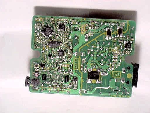
Click to zoom
Application Details
- Equipment Class
- JBP - Part 15 Class B Computing Device Peripheral
- Date of Grant
- Nov 07, 1999
- Application Purpose
- Original Equipment
- Date of Application
- Oct 18, 1999
- Equipment Note
- Digital Video Camera With PC Interface
- Country
- United States
Documents & Files
Document Text
Text extracted from the exhibit documents filed with the FCC. Open a document above to read the original.
Users Manual
Before attempting to connect, operate or adjust this product, please read these instructions thoroughly. Spanish Quick Use Guide is included. Guía para rápida consulta en español está incluida. R LSQTXXXX Model No. PV-DV600D Digital Video Camcorder Operating Instructions R TM TM Mini For assistance, call 1-800-211-PANA (7262) -TENTATIVE- EXHIBIT# 5 FIG NO. FCC ID: ACJ927129K MODEL NO. PV-DV600D OUR REF.: MKES99-F021 600.1-26.p6599/10/19, 13:531 2 For assistance, call 1-800-211-PANA(7262) Things You Should Know 1 pc. AC Adaptor (PV-DAC9) with AC Cable, DC Cable and Jack Box 1 pc. Shoulder Strap (VYCW0225) 1 pc. Battery Pack (PV-DBP8) 1 pc. Lens Cap (LSYF0358) Date of Purchase Dealer Purchased From Dealer Address Dealer Phone No. Model No. Serial No. Thank you for choosing Panasonic! You have purchased one of the most sophisticated and reliable products on the market today. Used properly, we’re sure it will bring you and your family years of enjoyment. Please take time to fill in the information below. The serial number is on the tag located on the underside of your Palmcorder. Be sure to retain this manual as your convenient Palmcorder information source. Unpack your Camcorder 1 pc. A/V Cable (VJAW0043) 1 pc. PC Connection Cable for Windows (LSJA0236) 600.1-26.p6599/10/19, 13:532 3 Getting Started For assistance, call 1-800-211-PANA(7262) This symbol warns the user that uninsulated voltage within the unit may have sufficient magnitude to cause electric shock. Therefore, it is dangerous to make any kind of contact with any inside part of this unit. This symbol alerts the user that important literature concerning the operation and maintenance of this unit has been included. Therefore, it should be read carefully in order to avoid any problems. CAUTION RISK OF ELECTRIC SHOCK DO NOT OPEN CAUTION: TO REDUCE THE RISK OF ELECTRIC SHOCK, DO NOT REMOVE COVER (OR BACK) NO USER-SERVICEABLE PARTS INSIDE REFER SERVICING TO QUALIFIED SERVICE PERSONNEL Mini Things You Should Know The above markings are located on the appliance bottom cover. Mini Safety Precautions WARNING: TO PREVENT FIRE OR SHOCK HAZARD, DO NOT EXPOSE THIS EQUIPMENT TO RAIN OR MOISTURE. YourPalmcorder is designed to record and play back in Standard Play (SP) mode only. This Palmcorder is equipped with the HQ System to provide excellent video pictures. It is recommended that only cassette tapes that have been tested and inspected for use in VCR machines with themark be used. This device complies with Part 15 of the FCC Rules. Operation is subject to the following two conditions: (1) This device may not cause harmful interference, and (2) this device must accept any interference received, including interference that may cause undesired operation. Note: This equipment has been tested and found to comply with Part 15 of the FCC Rules. These limits are designed to provide reasonable protection against harmful interference when operated in a residential environment. If this equipment does cause interference to radio or television reception, which can be determined by turning the equipment off and on, use the equipment in another location and/or utilize an electrical outlet different from that used by the receiver. If necessary, consult the dealer or an experienced radio/TV technician for help. You may find the booklet, ‘Something About Interference’ available from FCC local regional offices helpful. FCC Warning:To assure continued FCC compliance, use only the provided shielded interface cable with ferrite cores when connecting digital video camera to computer in accordance with instruction herein. Also, any unauthorized changes or modifications to this equipment could void the user’s authority to operate. 600.1-26.p6599/10/19, 13:533 4 For assistance, call 1-800-211-PANA(7262) 11. Grounding or Polarization — This video unit may be equipped with either a polarized 2-wire AC (Alternating Current) line plug (a plug having one blade wider than the other) or 3-wire grounding type plug, a plug having a third (grounding) pin. The 2-wire polarized plug will fit into the power outlet only one way. This is a safety feature. If you are unable to insert the plug fully into the outlet, try reversing the plug. If the plug still fails to fit, contact your electrician to replace your obsolete outlet. Do not defeat the safety purpose of the polarized plug. The 3-wire grounding type plug will fit into a grounding type power outlet. This is a safety feature. If you are unable to insert the plug into the outlet, contact your electrician to replace your obsolete outlet. Do not defeat the safety purpose of the grounding type plug. 12. Power-Cord Protection — Power-supply cords should be routed so that they are not likely to be walked on or pinched by items placed upon or against them, paying particular attention to cords of plugs, convenience receptacles, and the point where they exit from the unit. 13. Outdoor Antenna Grounding — If an outside antenna or cable system is connected to the video unit, be sure the antenna or cable system is grounded so as to provide some protection against voltage surges and built-up static charges. Part 1 of the Canadian Electrical Code, in USA Section 810 of the National Electrical Code, provides information with respect to proper grounding of the mast and supporting structure, grounding of the lead-in wire to an antenna discharge unit, size of grounding conductors, location of antenna discharge unit, connection to grounding electrodes, and requirements for the grounding electrode. 14. Lightning — For added protection of this video unit receiver during a lightning storm, or when it is left unattended and unused for long periods of time, unplug it from the wall outlet and disconnect the antenna or cable system. This will prevent damage to the video unit due to lightning and power-line surges. 1. Read Instructions — All the safety and operating instructions should be read before the unit is operated. 2. Retain Instructions — The saf…
Text truncated - open the document above for the full version.
Block Diagram
Description of Digital DeviceEXHIBIT #: 4-1 FCC ID: ACJ927129K OUR REF.: MKES99-F021 MODEL NO.: PV-DV600D Page 1/2 Technical Specification Power Source : DC 7.2 / 7.8 V Power Consumption : 7 W Video Recording System: EIA Standard (525 lines, 60 fields) NTSC color signal Frequency generated or used : 10 kHz - 49.152 MHz Operating Temperature : 0 - 40 Operating Humidity : 10 % - 75 % Device Operation DescriptionEXHIBIT #: 4-1 FCC ID : ACJ927129K OUR REF.: MKES99-F021 MODEL NO.: PV-DV600D Page 2/2 Performance Explanation of Digital Video Camera 1) Camera Mode(Camera->DV Output/Monitor Output/Tape Recording/DSC Recording) The light on the CCD through the lens is converted to the electric analog signal and it is forwarded to the Camera Process. In the Camera Process, the analog signal is converted to the digital signal by the built-in A/D Converter and is processed as image. Then, it is converted to the digital component signal. The digital component signal is forwarded to Format Process via the Video I/O Interface of the VCR Block, and is compressed and converted to the DV Format signal. The DV format signal is processed by the Tape Format and it is converted to Tape Recording signal for recording on the tape. On the other hand, it is processed by the DIF Process to output the DV Signal conformed with the IEEE1394 to the PCs or the different DVCs through the DV Cable. And, the D/A converted NTSC Video signal by Video I/O Interface is forwarded to the VIDEO AMP and the amplified VIDEO signal is output to TV monitors, etc. through Audio/Video I/O Terminals. 2) Playback Mode(Tape Signal->DV Output/Monitor Output) The signal by way of Cylinder Head from the tape is converted to the DV Format signal by the Format Process. The DV Format signal is processed by the DIF Process to output the DV Signal conformed with the IEEE1394 to the PCs or the different DVCs. This compressed DV signal is extracted. Then the D/A converted NTSC Video signal by Video I/O Interface is forwarded to the VIDEO AMP and the amplified VIDEO signal is output to TV monitors, etc. through Audio/Video I/O Terminals. 3) DV Input Mode(DV Input Signal->Monitor Output/Tape Recording) The DV signal conformed with the IEEE1394 via the DV Cable from the PCs or the different DVCs is converted to the DV Format signal by DIF Process. The DV format signal is processed by the Tape Format and it is converted to Tape Recording signal for recording on the tape. This compressed DV signal is extracted. Then the D/A converted NTSC Video signal by Video I/O Interface is forwarded to the VIDEO AMP and the amplified VIDEO signal is output to TV monitors, etc. through Audio/Video I/O Terminals. 4) ANALOG Mode(Analog Input Signal->DV Output/Tape Recording) The Video signal which was input on the Audi/Video I/O terminals is forwarded to the Analog Interface through the IN/OUT Control Selector. The Video signal is forwarded to the Video I/O Interface for the A/D conversion, then it is forwarded from the Video I/O Interface to the Format Process. And it is compressed and converted to the DV Format signal. The DV format signal is processed by the Tape Format and it is converted to Tape Recording signal for recording on the tape. On the other hand, it is processed by the DIF Process to output the DV Signal conformed with the IEEE1394 to the PCs or the different DVCs through the DV Cable. 5) DSC Still Image Output Mode(DSC Memory->RS232C/Monitor Output) The image stored on the memory of DSC is amplified by the RS-232C Driver and is output to the PCs, etc. through the RS-232C Cable. 6) Playback Still Image Output Mode(Tape Signal->Memory->RS-232C/Monitor) The still image stored on the memory of playback tape signal is amplified by the RS-232C Driver and is output to the PCs, etc. through the RS-232C Cable. EXHIBIT #: 4-2 FCC ID: ACJ927129K OUR REF.: MKES99-F021 MODEL NO.: PV-DV600D Page 1/2 EXHIBIT #: 4-2 FCC ID: ACJ927129K OUR REF.: MKES99-F021 MODEL NO.: PV-DV600D Page 2/2 List of Frequency CLOCK of Digital Video Camera CIRCUIT NameCLOCK Timing Generator27.0 MHz CCD13.5 MHz Camera Process13.5 MHz 4.5 MHz Camera I/F 13.5 MHz 18.0 MHz 24.576 MHz Format Process 41.85 MHz Camera CPU20.0 MHz CYL Head10 kHz 20.925 MHz 18.0 MHz DIF Process DC 49.152 MHz Power700 kHz Timer Clock 32.0 Hz Character Generator OSC 7.2 MHz VCR System CPU27.0 MHz LCD Process (PLL)19.07 MHz EVF Process (PLL)10.38 MHz
External Photos
EXHIBIT #: FCC ID: ACJ927129K OUR REF. : MKES99-F021 MODEL NO.: PV-DV600D Sheet 1 of 27 Sheets EXHIBIT #: FCC ID: ACJ927129K OUR REF. : MKES99-F021 MODEL NO.: PV-DV600D Sheet 2 of 27 Sheets EXHIBIT #: FCC ID: ACJ927129K OUR REF. : MKES99-F021 MODEL NO.: PV-DV600D Sheet 3 of 27 Sheets
External Photos
EXHIBIT #: FCC ID: ACJ927129K OUR REF. : MKES99-F021 MODEL NO.: PV-DV600D Sheet 25 of 27 Sheets AC Adaptor (PV-DAC10) AC Adaptor (PV-DAC10) EXHIBIT #: FCC ID: ACJ927129K OUR REF. : MKES99-F021 MODEL NO.: PV-DV600D Sheet 26 of 27 Sheets AC Adaptor PCB (Top view) AC Adaptor PCB (Top view) EXHIBIT #: FCC ID: ACJ927129K OUR REF. : MKES99-F021 MODEL NO.: PV-DV600D Sheet 27 of 27 Sheets AC Adaptor PCB (Bottom view)
ID Label/Location Info
EXHIBIT #: 1 FCC ID : ACJ927129K OUR REF. : MKES99-F021 MODEL NO.: PV-DV600D Sample of FCC Identifier FCC Statements for compliance with FCC Rules Part 15 in User's Manual EXHIBIT #: 2 FCC ID : ACJ927129K OUR REF. : MKES99-F021 MODEL NO.: PV-DV600D FCC IDENTIFIER
Internal Photos
EXHIBIT #: FCC ID: ACJ927129K OUR REF. : MKES99-F021 MODEL NO.: PV-DV600D Sheet 4 of 27 Sheets EXHIBIT #: FCC ID: ACJ927129K OUR REF. : MKES99-F021 MODEL NO.: PV-DV600D Sheet 5 of 27 Sheets Analogue PCB (Top View) Analogue PCB (Bottom View) EXHIBIT #: FCC ID: ACJ927129K OUR REF. : MKES99-F021 MODEL NO.: PV-DV600D Sheet 6 of 27 Sheets Camera Main PCB (Top View) Camera Main PCB (Bottom View) EXHIBIT #: FCC ID: ACJ927129K OUR REF. : MKES99-F021 MODEL NO.: PV-DV600D Sheet 7 of 27 Sheets Power PCB (Top View) Power PCB (Top View) EXHIBIT #: FCC ID: ACJ927129K OUR REF. : MKES99-F021 MODEL NO.: PV-DV600D Sheet 8 of 27 Sheets Power PCB (Bottom View) Power PCB (Bottom View) EXHIBIT #: FCC ID: ACJ927129K OUR REF. : MKES99-F021 MODEL NO.: PV-DV600D Sheet 9 of 27 Sheets CCD PCB (Bottom View) EXHIBIT #: FCC ID: ACJ927129K OUR REF. : MKES99-F021 MODEL NO.: PV-DV600D Sheet 10 of 27 Sheets CCD PCB (Bottom View) CCD PCB (Top View) EXHIBIT #: FCC ID: ACJ927129K OUR REF. : MKES99-F021 MODEL NO.: PV-DV600D Sheet 11 of 27 Sheets Microphone PCB (Bottom View) Microphone PCB (Bottom View) EXHIBIT #: FCC ID: ACJ927129K OUR REF. : MKES99-F021 MODEL NO.: PV-DV600D Sheet 12 of 27 Sheets Microphone PCB (Top View) Microphone PCB (Top View) EXHIBIT #: FCC ID: ACJ927129K OUR REF. : MKES99-F021 MODEL NO.: PV-DV600D Sheet 13 of 27 Sheets Jack PCB (Top view) Jack PCB (Bottom view)
Internal Photos
EXHIBIT #: FCC ID: ACJ927129K OUR REF. : MKES99-F021 MODEL NO.: PV-DV600D Sheet 14 of 27 Sheets Electronic view finder (Top view) Electronic view finder (Top view) EXHIBIT #: FCC ID: ACJ927129K OUR REF. : MKES99-F021 MODEL NO.: PV-DV600D Sheet 15 of 27 Sheets 3” LCD 3” LCD (Top view) EXHIBIT #: FCC ID: ACJ927129K OUR REF. : MKES99-F021 MODEL NO.: PV-DV600D Sheet 16 of 27 Sheets 3” LCD (Top view) 3” LCD (Top view) EXHIBIT #: FCC ID: ACJ927129K OUR REF. : MKES99-F021 MODEL NO.: PV-DV600D Sheet 17 of 27 Sheets 3” LCD (Bottom view) 3” LCD (Bottom view) EXHIBIT #: FCC ID: ACJ927129K OUR REF. : MKES99-F021 MODEL NO.: PV-DV600D Sheet 18 of 27 Sheets 3” LCD 3” LCD EXHIBIT #: FCC ID: ACJ927129K OUR REF. : MKES99-F021 MODEL NO.: PV-DV600D Sheet 19 of 27 Sheets 3” LCD EXHIBIT #: FCC ID: ACJ927129K OUR REF. : MKES99-F021 MODEL NO.: PV-DV600D Sheet 20 of 27 Sheets 4” LCD 4” LCD (Top view) EXHIBIT #: FCC ID: ACJ927129K OUR REF. : MKES99-F021 MODEL NO.: PV-DV600D Sheet 21 of 27 Sheets 4” LCD (Top view) 4” LCD (Top view) EXHIBIT #: FCC ID: ACJ927129K OUR REF. : MKES99-F021 MODEL NO.: PV-DV600D Sheet 22 of 27 Sheets 4” LCD (Top view) 4” LCD (Bottom view) EXHIBIT #: FCC ID: ACJ927129K OUR REF. : MKES99-F021 MODEL NO.: PV-DV600D Sheet 23 of 27 Sheets 4” LCD 4” LCD EXHIBIT #: FCC ID: ACJ927129K OUR REF. : MKES99-F021 MODEL NO.: PV-DV600D Sheet 24 of 27 Sheets 4” LCD
Operational Description
Description of Application Model FCC ID : ACJ927129K OUR REF. : MKES99-F021 MODEL NO.: PV-DV600D Application model is as below. FCC ID:ACJ927129K Application name:Digital Video Camera Grantee name:Matsushita Electric Industrial Co., Ltd. Manufacturer:Matsushita-Kotobuki Electronics Ind. Ltd. Model No.:PV-DV600D Brand name:Panasonic Chassis No.:KDV-2000 Cabinet Material:Plastics LCD Monitor:3” LCD or 4” LCD
Test Report
EXHIBIT #: 3-1 FCC ID: ACJ927129K OUR REF.: MKES99-F021 MODEL NO.: PV-DV600D Sheet 4 of 16 Sheets 3” LCD Type 1) 15.107 Power Line Conducted Voltage Meter Reading (dBuV)Interference (dBuV) Mode Freq. (MHz) 1-end & Grounded The other- End & Gro. LISN Factor (dB) Matching Pad Loss (dB) 1-end & Grounded The other- End & Gro 0.5631.630.00.16.237.936.3 0.6432.832.40.16.239.138.7 0.8931.932.50.16.238.238.8 2.0933.234.00.26.239.640.4 5.1433.934.20.46.240.540.8 DV 6.1133.634.40.46.240.241.0 0.6431.332.40.16.237.638.7 1.1332.432.80.16.238.739.1 1.9333.833.00.26.240.239.4 4.4233.533.80.36.240.040.3 4.8333.233.70.36.239.740.2 Serial 5.7931.633.70.46.238.240.3 Note: 1. Sample calculation at DV Mode 1-end & Gro., 0.56 MHz ; 31.6 + 0.1 + 6.2 = 37.9 (dBuV) 2. Measuring Instruments: a) Field strength meter - Kyoritsu Electric Work Co., Ltd. Model : KNM-402C (1) Detector function : CISPR Q-PEAK (2) IF band width : 9 kHz (3) Input impedance : 75 ohms b) Line impedance stabilized network (LISN) - Kyoritsu Electric Work Co., Ltd. Model : KNW-406, KNW-407 50 ohms / 50 uH network c) Matching pad - Kyoritsu Electric Work Co., Ltd. Model : KPD-401 3. The spectrum was checked from 0.45 MHz to 30 MHz and the six highest emissions relative to the appropriate limit were measured and reported. EXHIBIT #: 3-1 FCC ID: ACJ927129K OUR REF.: MKES99-F021 MODEL NO.: PV-DV600D Sheet 5 of 16 Sheets 4” LCD Type 2) 15.107 Power Line Conducted Voltage Meter Reading (dBuV)Interference (dBuV) Mode Freq. (MHz) 1-end & Grounded The other- End & Gro. LISN Factor (dB) Matching Pad Loss (dB) 1-end & Grounded The other- End & Gro 0.5631.930.80.16.238.237.1 0.6433.132.20.16.239.438.5 0.8931.332.00.16.237.638.3 2.0932.733.60.26.239.140.0 5.1433.834.00.46.240.440.6 DV 6.1133.433.90.46.240.040.5 0.6430.631.60.16.236.937.9 1.1332.533.10.16.238.839.4 1.9333.733.50.26.240.139.9 4.4233.233.50.36.239.740.0 4.8332.433.60.36.238.940.1 Serial 5.7931.833.20.46.238.439.8 Note: 1. Sample calculation at DV Mode 1-end & Gro., 0.56 MHz ; 31.9 + 0.1 + 6.2 = 38.2 (dBuV) 2. Measuring Instruments: a) Field strength meter - Kyoritsu Electric Work Co., Ltd. Model : KNM-402C (1) Detector function : CISPR Q-PEAK (2) IF band width : 9 kHz (3) Input impedance : 75 ohms b) Line impedance stabilized network (LISN) - Kyoritsu Electric Work Co., Ltd. Model : KNW-406, KNW-407 50 ohms / 50 uH network c) Matching pad - Kyoritsu Electric Work Co., Ltd. Model : KPD-401 3. The spectrum was checked from 0.45 MHz to 30 MHz and the six highest emissions relative to the appropriate limit were measured and reported. EXHIBIT #: 3-1 FCC ID: ACJ927129K OUR REF.: MKES99-F021 MODEL NO.: PV-DV600D 3” LCD Type Sheet 6 of 16 Sheets 3) 15.109 Radiated Emission Meter Reading Open Volt. (dBuV) Emission at 3 meters (DbuV)Mode Freq. (MHz) Horiz.Vert. Correction Factor (dB) Open Vol. Horiz.Vert. 108.0024.1 7.513.637.721.1 121.5021.9 6.215.437.321.6 256.5016.2 5.521.137.326.6 337.5021.315.119.741.034.8 351.0020.515.420.040.535.4 DV 391.5016.015.820.936.936.7 108.0021.8 8.513.635.422.1 121.5020.4 6.415.435.821.8 256.5015.1 4.721.136.225.8 337.5018.613.219.738.332.9 351.0017.614.120.037.634.1 Serial 391.5017.516.320.938.437.2 Note: 1. Sample calculation at DV Mode Horiz., 108.00 MHz ; 24.1 + 13.6 = 37.7 (dBuV/m) 2. Measuring Instruments: a) Field strength meter - Rohde & Schwarz (for 30 MHz to 1 G Hz) Model : ESVP (1) Frequency range : 20 MHz to 1300 MHz (2) RF Input : 50 ohms (3) IF band width : 7.5 kHz / 12 kHz/ 120 kHz / 1 MHz (4) Detector function: Average/ CISPR Q-PERK/PERK c) Receiving antenna - Schwarzbeck Model : VHA9103 30 - 300 MHz Model : UHALP9107 300 - 1000 MHz - The Electro-Machanics Company Model : 3115 1 – 18 GHz 3. The Spectrum was checked from 30 MHz to 1000 MHz and the six highest emissions relative to the appropriate limit were measured and reported. EXHIBIT #: 3-1 FCC ID: ACJ927129K OUR REF.: MKES99-F021 MODEL NO.: PV-DV600D 4” LCD Type Sheet 7 of 16 Sheets 4) 15.109 Radiated Emission Meter Reading Open Volt. (dBuV) Emission at 3 meters (DbuV)Mode Freq. (MHz) Horiz.Vert. Correction Factor (dB) Open Vol. Horiz.Vert. 108.0023.8 8.113.637.421.7 121.5022.2 6.915.437.622.3 256.5015.1 6.121.136.227.2 337.5020.815.419.740.535.1 351.0020.014.820.040.034.8 DV 391.5015.315.120.936.236.0 108.0021.6 9.813.635.223.4 121.5020.4 6.215.435.821.6 256.5015.1 5.121.136.226.2 337.5018.213.319.737.933.0 351.0018.114.620.038.134.6 Serial 391.5017.216.520.938.137.4 Note: 1. Sample calculation at DV Mode Horiz., 108.00 MHz ; 23.8 + 13.6 = 37.4 (dBuV/m) 2. Measuring Instruments: a) Field strength meter - Rohde & Schwarz (for 30 MHz to 1 G Hz) Model : ESVP (1) Frequency range : 20 MHz to 1300 MHz (2) RF Input : 50 ohms (3) IF band width : 7.5 kHz / 12 kHz/ 120 kHz / 1 MHz (4) Detector function: Average/ CISPR Q-PERK/PERK c) Receiving antenna - Schwarzbeck Model : VHA9103 30 - 300 MHz Model : UHALP9107 300 - 1000 MHz - The Electro-Machanics Company Model : 3115 1 – 18 GHz 3. The Spectrum was checked from 30 MHz to 1000 MHz and the six highest emissions relative to the appropriate limit were measured and reported.
Test Setup Photos
EXHIBIT #: 3-1 FCC ID: ACJ927129K OUR REF.: MKES99-F021 MODEL NO.: PV-DV600D Sheet 8 of 16 Sheets 15.107 POWER LINE CONDUCTED VOLTAGE - CONFIGURATION OF THE EQUIPMENT UNDER TEST - ( Arrangement of interface cable on the test table ) DV Mode EXHIBIT #: 3-1 FCC ID: ACJ927129K OUR REF.: MKES99-F021 MODEL NO.: PV-DV600D Sheet 9 of 16 Sheets 15.107 POWER LINE CONDUCTED VOLTAGE - CONFIGURATION OF THE EQUIPMENT UNDER TEST - ( Arrangement of interface cable on the test table ) Serial Mode EXHIBIT #: 3-1 FCC ID: ACJ927129K OUR REF.: MKES99-F021 MODEL NO.: PV-DV600D Sheet 10 of 16 Sheets 15.109 RADIATED EMISSION - CONFIGURATION OF THE EQUIPMENT UNDER TEST - ( Arrangement of interface cable on the test table ) DV Mode EXHIBIT #: 3-1 FCC ID: ACJ927129K OUR REF.: MKES99-F021 MODEL NO.: PV-DV600D Sheet 11 of 16 Sheets 15.109 RADIATED EMISSION - CONFIGURATION OF THE EQUIPMENT UNDER TEST - ( Arrangement of interface cable on the test table ) DV Mode
Contact Information
Applicant
Ben Botros(Project Manager)
Technical Contact
Matsushita Electric Corp of AmericaRichard Mullen
[email protected](201) 348-7758
One Panasonic Way, Panazip 4B-8 · Secaucus, New Jersey · United States
Test Firm
Panasonic Healthcare Co., LtdOsamu Kobashi
[email protected]81-897-56-1111
Technical Specifications
| # | Rule Parts | Frequency Range | Power Output |
|---|---|---|---|
| 1 | 15B | - | - |
Other Applications from Panasonic Corporation of North America
ACJ-EAH-A1000
Aug 19, 2026Digital Wireless Stereo Headphones
Equipment Class
DSS - Part 15 Spread Spectrum TransmitterACJ9TGFZVNF3G1
Jun 16, 2026Contactless Smart Card Reader
Equipment Class
DXX - Part 15 Low Power Communication Device Transmitter
ACJ932AM2301
Jan 29, 2025Car AV Control Unit for CDC
Equipment Class
DTS - Digital Transmission SystemACJ96NKX-TGEA60B
Aug 13, 2024DECT Handset
Equipment Class
PUE - Part 15 Unlicensed PCS portable Tx held to earACJ96NKX-TGE630B
Aug 12, 2024DECT Base Unit
Equipment Class
PUB - Part 15 Unlicensed PCS Base Station