ACLAP7G81Microwave Oven
Panasonic Corporation of North America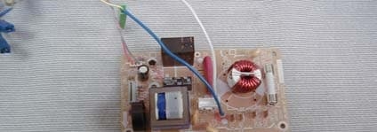
Click to zoom
Application Details
- Equipment Class
- 8CC - Part 18 Consumer Device
- Date of Grant
- Dec 29, 2004
- Application Purpose
- Original Equipment
- Date of Application
- Dec 13, 2004
- Equipment Note
- Microwave Oven
- Frequency Range
- 2400.00000000 - 2500.00000000
- Country
- United States
Documents & Files
Document Text
Text extracted from the exhibit documents filed with the FCC. Open a document above to read the original.
Cover Letter(s)
MATSUSHITA HOME APPLIANCE COMPANY, 1711 N . RANDALL ROAD, E-Zip:E-2J-16 MICROWAVE TECHNICAL LABORATORY ELGIN, IL 60123-7847 Direct Dial Line: (847)468-5946 Fax.: (847)468-5963 MAC December 14, 2004 Federal Communications Commission Equipment Authorization Branch 7435 Oakland Mills Road Columbia, MD. 21046 SUBJECT: FILING FOR CERTIFICATION GRANTEE CODE ACL. We are sending application for models with FCC Identifier ACLAP7G81. These Microwave Ovens are to be approved under the regulations in effect for devices to be manufactured after July 11, 2005. In the submission you will find exhibits for measurements taken in both Radiated and Line Conducted modes. As permitted by FCC rules, these measurements were taken by separate labs. Each of these labs are registered and have submitted documents which are on file with the FCC. Efforts are currently under way to have all measurements taken by the same lab, in the future. For a quick reference to all of the exhibits submitted, please reference the Application Index and Summary. If there are any questions pertaining to this application, please contact me. Sincerely, Jim Kingsley Senior Engineer, Product Safety Regulations Dept. Cc: S. Yamashita
Internal Photos
Exhibit 2-C2 Left side view, Exhibit 2-D2 Right side view, No enclosure NN-S335WFNo enclosure NN-S335WF Exhibit 2-F2 Top view, Exhibit 2-J View of Door Choke No enclosure NN-S335WFConstruction Exhibit 2-H View of Control CircuitryExhibit 2-I View of Magnetron and Power Line Filter2M210-M1
Test Report
APPLICATION FOR CERTIFICATION ACLAP7G81 MODEL NO. FCC ID NN-S335BF ACLAP7G81 NN-S335MF ACLAP7G81 NN-S335WF ACLAP7G81 LIST OF EXHIBITS EXHIBIT 1A : TECHNICAL REPORT (Radiated Emissions) EXHIBIT 1B : TECHNICAL REPORT (Line Conducted Emissions) EXHIBIT 2 : PHOTOGRAPHS OF MAGNETRON AND COMPONENTS EXHIBIT 3 : SAMPLE AND LOCATION OF FCC ID LABEL EXHIBIT 4 : SCHEMATIC DIAGRAMS EXHIBIT 5A : REPORT OF MEASUREMENTS (Radiated Emissions) EXHIBIT 5B : REPORT OF MEASUREMENTS (Line Conducted Emissions) EXHIBIT 6A : LIST OF MEASURING EQUIPMENT AND CALIBRATION (Radiated Emissions) EXHIBIT 6B : LIST OF MEASURING EQUIPMENT AND CALIBRATION (Line Conducted Emissions) EXHIBIT 7 : OPERATING INSTRUCTIONS EXHIBIT 8 : INSTALLATION INSTRUCTIONS ACLAP7G81 EXHIBIT 1-1 TECHNICAL REPORT 1. DESCRIPTION OF MEASUREMENT FACILITY: The description of the measurement facility is already on file with the FCC laboratory. Please refer to the commission's reference 31010/EQU 4-3-0A. 2. INSTALLATION INSTRUCTIONS: See EXHIBIT 7. 3. OPERATING INSTRUCTIONS: See EXHIBIT 8. 4. APPLICANT: MATSUSHITA HOME APPLIANCE COMPANY MICROWAVE TECHNICAL LAB.,E-Zip E2J-16 1711 N. Randall Road Elgin, Illinois 60123-7847 5. MANUFACTURER: PANASONIC HOME APPLIANCES, MICROWAVE OVEN CO. LTD. (PHAMOS) 868 Long Dong Road Pu Dong, Shanghai 201203 CHINA 6. MEASUREMENT SITE:(Radiated Emissions) FCC Registration Number 96247 PANASONIC MAGNETRON LAB. PANASONIC INDUSTRIAL COMPANY 1707 N. Randall Road Elgin, Il 60123-7847 MEASUREMENT SITE: (Line Conducted Emissions). FCC Registration Number 767285 Jiangsu TUV Product Service Ltd. 10 Huaxia M. Rd. Wuxi, Jiangsu, 214100 China 7. EQUIPMENT IDENTIFICATION Model No. : NN-S335BF,NN-S335MF, NN-S335WF Brand Name : Panasonic FCC ID : ACLAP7G81 ACLAP7G81 EXHIBIT 1-2 8. EQUIPMENT SPECIFICATIONS: Electrical Power Requirement: 120V, 60Hz, 10.5A Nominal Operating Frequency: 2450 MHz Maximum RF Energy Generated: 800 W (IEC 705) Magnetron Type: 2M210 Feed Type and Location: Through the wave guide on the right sidewall of the oven. Stirrer: Turntable Type Cabinet Dimensions: (W) 482 x (H) 282 x (D) 354 (mm) Oven Cavity Dimensions: (W) 325 x (H) 218 x (D) 330 (mm) Door Viewing Area Dimensions: (W) 204 x (H) 102 (mm) Door Seal Type: Slit Choke seal and capacitive seal method 9. DESCRIPTION OF DIFFERENCES Model No. NN-S335 BF/MF/WF Input Power 120Vac, 10.5A Output Power 800W Magnetron 2M210-M1 Brand Panasonic ACLAP7G81 EXHIBIT 2 PHOTOGRAPHS OF EQUIPMENT EXHIBIT 2-A: FRONT VIEW OF MODEL NN-S335WF EXHIBIT 2-B: FRONT VIEW DOOR OPEN, MODEL NN-S335WF EXHIBIT 2-C1: LEFT SIDE VIEW OF MODEL NN-S335WF EXHIBIT 2-C2: LEFT SIDE VIEW OF MODEL NN-S335WF WITH ENCLOSURE REMOVED EXHIBIT 2-D1: RIGHT SIDE VIEW OF MODEL NN-S335WF EXHIBIT 2-D2: RIGHT SIDE VIEW OF MODEL NN-S335WF WITH ENCLOSURE REMOVED EXHIBIT 2-E:REAR VIEW OF MODEL NN-S335WF EXHIBIT 2-F1: TOP VIEW OF MODEL NN-S335WF EXHIBIT 2-F2: TOP VIEW OF MODEL NN-S335WF WITH ENCLOSURE REMOVED EXHIBIT 2-G: BOTTOM VIEW OF MODEL NN-S335WF EXHIBIT 2-H: VIEW OF CONTROL CIRCUITRY & POWER LINE FILTER, MODEL NN-S335WF EXHIBIT 2-I: VIEW OF MAGNETRON TYPE 2M210-M1 EXHIBIT 2-J: VIEW OF DOOR CHOKE CONSTRUCTION ILLUSTRATING INTEGRAL CHOKE TYPE ACLAP7G81 EXHIBIT 5A REPORT OF MEASUREMENTS 1. MODEL NO.: NN-S335WF SERIAL NO. PP-5001 MAGNETRON TYPE NO.: 2M210-M1 2. MEASUREMENT DATE: 11/12/04 3. LIST OF MEASURING EQUIPMENT AND CALIBRATION DATA: REFER TO ATTACHED EXHIBIT 6 4. INVESTIGATED FREQUENCY RANGE: 100Mhz to 4th Harmonic 5. DATA SUMMARY: Safety Check: <0.04 MW/cm2 Radiated Field Strength: ( uV/m @ 300m ) Limit Fundamental: 2478 MHz 1960.61uv/m N/A 2nd. Harmonic: 4938 MHz 1.64uv/m 27.51 3rd. Harmonic: 7432 MHz 1.53uv/m " 4th. Harmonic: 8585 MHz 2.40uv/m " Spurious: 2387 Mhz 1.56uv/m " Emission Sideband: 2400 MHz 0.21uv/m " Emission Sideband: 2500 MHz 0.32uv/m " Greater than 4th. Harmonic not measurable Maximum Frequency Variation: 2469 to 2471 MHz (96V ~ 150V/ 1000 ml water load) Maximum Frequency Variation: 2471 to 2479 MHz (1000 ml - 200ml water load) Total Power Input to Oven: 1225 watts Power Developed in Dummy Load: 606 watts Supply Voltage: 120 Volts, 60Hz, 11.1A ACLAP7G81 EXHIBIT 5B REPORT OF MEASUREMENTS 1. MODEL NO.: NN-S335WF SAMPLE NO. S41026021 MAGNETRON TYPE NO.: 2M210-M1 2. MEASUREMENT DATE: 11/11/04 3. LIST OF MEASURING EQUIPMENT AND CALIBRATION DATA: REFER TO ATTACHED EXHIBIT 6B 4. INVESTIGATED FREQUENCY RANGE: 0.15MHz to 30MHz 5. DATA SUMMARY: Selected Peak Readings (Refer to Spectrum Analyzer plot for complete readings). Power Line High Side Frequency QP Level QP Limit QP Delta MHz dBuV dBuV dB 0.95265 21.71 56.00 34.29 1.39649 34.33 56.00 21.67 2.18187 40.68 56.00 15.32 Frequency AV Level AV Limit AV Delta MHz dBuV dBuV dB Peak Readings are not recorded when there is more than 6dB margin to limit for all measured frequencies. Power Line Neutral Side Frequency QP Level QP Limit QP Delta MHz dBuV dBuV dB 1.09084 43.59 56.00 12.41 1.25908 43.67 56.00 12.33 Frequency AV Level AV Limit AV Delta MHz dBuV dBuV dB Peak Readings are not recorded when there is more than 6dB margin to limit for all measured frequencies.
Contact Information
Applicant
Ben Botros(Manager - Regulatory & Compliance)
Technical Contact
Matsushita Home Appliance CompanyJames R Kingsley
[email protected]847 468-5946
1711 N. Randall Road · Elgin, Illinois · United States
Non-Technical Contact
Matsushita Home Appliance CompanyJames R Kingsley
[email protected]847 468-5946
Test Firm
Panasonic Industrial CompanyMitsuhiro Okamoto
Technical Specifications
| # | Rule Parts | Frequency Range | Power Output |
|---|---|---|---|
| 1 | 18 | 2.40 GHz - 2.50 GHz | 800 W |
Other Applications from Panasonic Corporation of North America
ACLAP3L41
May 15, 2026Microwave Oven with two Magnetrons Model 2M261-M32
Equipment Class
8CC - Part 18 Consumer Device
ACLAP3L61
May 13, 2026Microwave Oven with two Magnetrons Model 2M261-M32
Equipment Class
8CC - Part 18 Consumer Device
ACLAP3L51
May 13, 2026Microwave Oven with two Magnetrons Model 2M261-M32
Equipment Class
8CC - Part 18 Consumer Device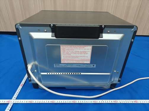
ACLAPDB71
Mar 06, 2026Microwave Oven with Magnetron
Equipment Class
8CC - Part 18 Consumer Device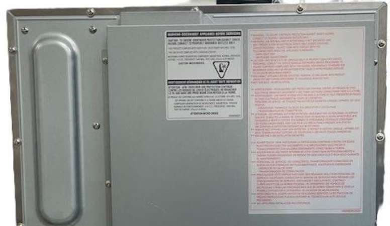
ACLAP3K21
Feb 16, 2026Microwave Oven with Magnetron 2M261-M32
Equipment Class
8CC - Part 18 Consumer Device