ADV0712902Scanning Receiver
General Research of Electronics Inc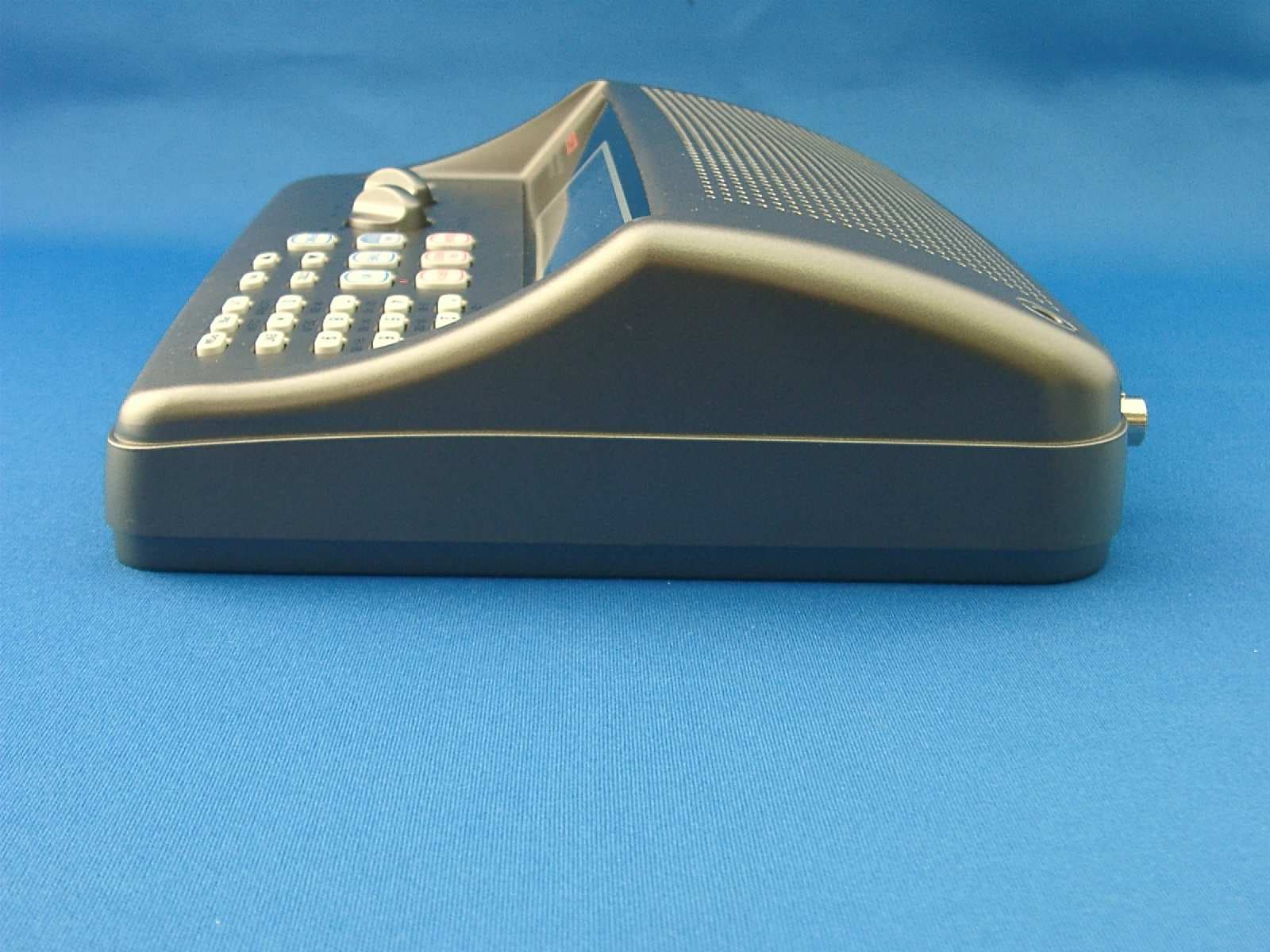
Click to zoom
Application Details
- Equipment Class
- CSR - Scanning Receiver
- Date of Grant
- Mar 14, 2010
- Application Purpose
- Original Equipment
- Date of Application
- Mar 14, 2010
- Equipment Note
- Scanning Receiver
- Frequency Range
- 380.00000000 - 512.00000000
- Country
- Japan
Documents & Files
Document Text
Text extracted from the exhibit documents filed with the FCC. Open a document above to read the original.
Users Manual
PSR-200U Owner’s Manual Draft PSR-200U 200-Channel VHF/Air/UHF Desktop Scanner Owner’s Manual GRE CONTENTS Features Preparation Power Sources Using AC Power Using Vehicle Battery Power Connecting the Supplied Antenna Connecting an Outdoor Antenna Connecting an Earphone/Headphones Listening Safely Connecting an Extension Speaker About Your Scanner About the Keypad A Look at the Display Understanding Banks Understanding Channel Storage Banks FM Radio Channels Service Search Operation Understanding 3 Modes Turning On the Scanner/Setting Volume and Squelch Storing Known Frequencies into Channels Finding and Storing Active Frequencies Searching the Service Search Band Using Tune Copying a Frequency into a Vacant Channel in a Specified Bank Copying a Frequency into a Specified Channel Scanning the Stored Channels Page 1 PSR-200U Owner’s Manual Draft Turning Channel-Storage Banks Off and On Monitoring a Stored Channel Clearing a Stored Channel FM Radio Operation Monitoring Stored FM Radio Channel Listening to the Marine Bank Listening to the Weather Band Listening to a Weather Channel SAME Standby Mode Skywarn Special Features Using CTCSS and DCS Delay Locking Out Channels or Frequencies Locking Out Channels Locking Out Marine Channels Locking Out Frequencies Reviewing Locked-Out Frequencies Removing Lockouts From All Frequencies in a Service Search Band Using Priority Turning the Key Tone On and Off Cloning the Programmed Data Initializing the Scanner A General Guide to Scanning Birdie Frequencies Frequency Conversion FAQs Care In Case of Fault Specifications FEATURES Your new PSR-200U 200 Channel plus 20 FM channels VHF/Air/UHF Desktop Scanner lets you scan conventional transmissions, and is preprogrammed with search banks for Page 2 PSR-200U Owner’s Manual Draft convenience. You press a FM RADIO key, you can quickly listen to the local broadcast stations. This scanner gives you direct access to over 22,000 exciting frequencies, including those used by police and fire departments, ambulance services, aircraft, and amateur radio services, and you can change your selection at any time. Your scanner also has these special features: Service Search Bands — let you search preset frequencies in separate marine, fire/police, aircraft, and ham banks, to make it easy to locate specific types of calls. FM Radio — lets you receive FM broadcast for your local area. Display Backlight — makes the scanner easy to read in low-light situations. Lockout Function — lets you set your scanner to skip over specified channels or frequencies when scanning or searching. Ten Channel-Storage Banks — you can store 20 channels in each bank (200 total channels), letting you group channels so you can more easily identify calls. Tune — lets you tune for new and unlisted frequencies starting from a specified frequency. SAME/FIPS Weather Alert — displays the weather event for the specific cities or counties you choose so you can hear the alert tone. Memory Backup — keeps the frequencies stored in memory for an extended time during a power loss. Scan Delay — delays scanning for about 2 seconds before moving to another channel, so you can hear more replies that are transmitted on the same channel. Priority Channel — lets you set the scanner to check one channel every 2 seconds so you do not miss transmissions. Page 3 PSR-200U Owner’s Manual Draft Tone Squelch (CTCSS and DCS) — decodes and displays the CTCSS or DCS tone signal. Data Cloning — lets you transfer the programmed data to another PSR-200U scanner. Liquid-Crystal Display — makes it easy to view and change programming information. Supplied Telescoping Antenna — provides good reception of strong local signals. External Antenna Connector — lets you connect an external antenna (not supplied) with a BNC connector to the scanner for improved reception of distant/weaker signals. Your PSR-200U scanner can receive these bands: Frequency Range (MHz) Types of Transmissions 29–54 10-Meter Ham Band, VHF Lo, 6-Meter Ham Band 87.3–107.9 FM broadcast 108–136.99166 Aircraft 137–174 Military Land Mobile, 2-Meter Ham Band, VHF Hi 380–512 UHF Aircraft, Federal Government, 70-cm Ham Band, UHF Standard Band, UHF “T” Band Note: See “Specifications” on Page XX for more information about the scanner’s frequency steps. © 2010 General Research of Electronics, Inc. All Rights Reserved. We encourage responsible, safe and legal scanner use. THE FCC WANT YOU TO KNOW This equipment has been tested and found to comply with the limits for a scanning receiver, pursuant to Part 15 of the FCC Rules. These limits are designed to provide reasonable protection against harmful interference in a residential installation. This equipment generates, uses and can radiate radio frequency energy and, if not installed and used in Page 4 PSR-200U Owner’s Manual Draft accordance with the instructions, may cause harmful interference to radio communications. However, there is no guarantee that interference will not occur in a particular installation. If this equipment does cause harmful interference to radio or television reception, which can be determined by turning the equipment off and on, the user is encouraged to try to correct the interference by one or more of the following measures: • Reorient or relocate the receiving antenna. • Increase the separation between the equipment and receiver. • Connect the equipment into an outlet on a circuit different from that to which the receiver is connected. • Consult the dealer or an experienced radio/TV technician for help. SCANNING LEGALLY Your scanner covers frequencies used by many different groups including police and fire departments, ambulance services, government agencies, private companies, amateur radio, military operations, pager services, and wireline (telephone and telegraph) service providers. It is legal to listen to almost every transmission you should never intentionally listen to. These include: • Telephone conversations (cellular, cordless, or other private …
Text truncated - open the document above for the full version.
Attestation Statements
Phone: +813-5439-3611 SHIBA NO.3 AMEREX BLDG. 3-12-17 MITA, MINATO-KU TOKYO 108-0073, JAPAN Fax: +813-5439-3644 GENERAL RESEARCH OF ELECTRONICS, INC. January 29, 2010 Federal Communications Commission Authorization and Evaluation Division Laboratory Division 7435 Oakland Mills Road Colombia, MD 21046 Ref.: FCC ID: ADV0712902 This is to clarify that the above equipment is incapable of operating (tuning) or readily being altered by the user to operate, within the frequency bands to the Cellular Radiotelephone Service. The frequencies in question are deleted from the ROM during manufacture, and cannot be restored through any readily available process or component such as: installation of cuts, jumper wires, resistors, diodes, or plug-in IC’s; deletion of such items; or reprogramming via access codes or external devices such as a personal computer. The receiver is incapable of converting digital cellular transmissions to analog voice audio. Assessing the vulnerability of the receiver to possible modification The receiver has the possibility of reducing the threshold value to discern transmissions from the Cellular Radiotelephone Service by making modification such as adding jumper wire to the UHF RF tuning circuit and UHF mixer circuit. Design features that prevent modification of the receiver to receive Cellular Service The scanning receiver is designed to prevent any attempt for the user to modify the receiver to receive transmissions from the Cellular Radiotelephone Service by using epoxy to cover the required parts of the UHF RF tuning circuit. PRODUCT DEVELOPMENT & MANUFACTURING GENERAL RESEARCH OF ELECTRONICS, INC. Testing method used to determine compliance with the 38 dB rejection ratio Test set-up: Equipment Setup Block Diagram Test Test frequencies: 869.00MHz, 877.03MHz, 885.06MHz, 893.09MHz easurement method rm initial screening, adjust EUT’s for the Squelched Threshold to suppress audio utput. . (The shold sensitivity of -6 dBuV.) This is approximately 66-38=28dB above the FCC limit.) (3) Turn EUT on and search cellular frequencies on all of the receiving ranges. (4) List all detected frequencies if EUT detects any. (5) Repeat the above procedure for each of the other cellular test frequencies. (6) To determine actual image rejection ratio for a detected frequency, perform the following steps. (7) Set both of EUT and SSG’s frequency to the frequency gained by the above screening. INAD and record the gained level. Note the gained conditions: AF Signal : 1 kHz FM Deviation : +/- 3kHz AM Modulation : 60 % 824.00MHz, 832.03MHz, 840.06MHz, 848.09MHz M (1) To perfo o (2) Set SSG’s frequency to a cellular band test frequency and apply 60dBuV RF level to EUT 60dBuV signal level corresponds to approximately 66dB above the Squelch Thre (8) Adjust SSG’s RF output on EUT for 12dB S SSG’s level is EUT‘s receiving sensitivity.
Cover Letter(s)
Phone: +813-5439-3611 SHIBA NO.3 AMEREX BLDG. 3-12-17 MITA, MINATO-KU TOKYO 108-0073, JAPAN Fax: +813-5439-3644 GENERAL RESEARCH OF ELECTRONICS, INC. January 29, 2010 Federal Communications Commission Authorization and Evaluation Division Laboratory Division 7435 Oakland Mills Road Colombia, MD 21046 Ref.: FCC ID: ADV0712902 This is to clarify that the above equipment is incapable of operating (tuning) or readily being altered by the user to operate, within the frequency bands to the Cellular Radiotelephone Service. The frequencies in question are deleted from the ROM during manufacture, and cannot be restored through any readily available process or component such as: installation of cuts, jumper wires, resistors, diodes, or plug-in IC’s; deletion of such items; or reprogramming via access codes or external devices such as a personal computer. The receiver is incapable of converting digital cellular transmissions to analog voice audio. Assessing the vulnerability of the receiver to possible modification The receiver has the possibility of reducing the threshold value to discern transmissions from the Cellular Radiotelephone Service by making modification such as adding jumper wire to the UHF RF tuning circuit and UHF mixer circuit. Design features that prevent modification of the receiver to receive Cellular Service The scanning receiver is designed to prevent any attempt for the user to modify the receiver to receive transmissions from the Cellular Radiotelephone Service by using epoxy to cover the required parts of the UHF RF tuning circuit. PRODUCT DEVELOPMENT & MANUFACTURING GENERAL RESEARCH OF ELECTRONICS, INC. Testing method used to determine compliance with the 38 dB rejection ratio Test set-up: Equipment Setup Block Diagram Test Test frequencies: 869.00MHz, 877.03MHz, 885.06MHz, 893.09MHz easurement method rm initial screening, adjust EUT’s for the Squelched Threshold to suppress audio utput. . (The shold sensitivity of -6 dBuV.) This is approximately 66-38=28dB above the FCC limit.) (3) Turn EUT on and search cellular frequencies on all of the receiving ranges. (4) List all detected frequencies if EUT detects any. (5) Repeat the above procedure for each of the other cellular test frequencies. (6) To determine actual image rejection ratio for a detected frequency, perform the following steps. (7) Set both of EUT and SSG’s frequency to the frequency gained by the above screening. INAD and record the gained level. Note the gained conditions: AF Signal : 1 kHz FM Deviation : +/- 3kHz AM Modulation : 60 % 824.00MHz, 832.03MHz, 840.06MHz, 848.09MHz M (1) To perfo o (2) Set SSG’s frequency to a cellular band test frequency and apply 60dBuV RF level to EUT 60dBuV signal level corresponds to approximately 66dB above the Squelch Thre (8) Adjust SSG’s RF output on EUT for 12dB S SSG’s level is EUT‘s receiving sensitivity.
External Photos
External Photographs FCC ID: ADV0712902
Test Report
EMC Report for GRE America on the model ADV0712902 G100036448MPK-001 Page 1 of 22 TEST REPORT Report Number: G100036448MPK-001 Project Number: G100036448 February 26, 2010 Testing performed on the Scanner Model Number: ADV0712902 FCC ID: ADV0712902 to FCC Part 15, Subpart B Class: B for GRE America Test Performed by: Test Authorized by: Intertek 1365 Adams Court Menlo Park, CA 94025 GRE America 425 Harbor Blvd. Suite B Belmont, CA 94002 Prepared by: Date: February 26, 2010 Marcos A. Rodriguez Reviewed by: Date: February 26, 2010 Krishna K Vemuri This report is for the exclusive use of Intertek's Client and is provided pursuant to the agreement between Intertek and its Client. Intertek's responsibility and liability are limited to the terms and conditions of the agreement. Intertek assumes no liability to any party, other than to the Client in accordance with the agreement, for any loss, expense or damage occasioned by the use of this report. Only the Client is authorized to copy or distribute this report and then only in its entirety. Any use of the Intertek name or one of its marks for the sale or advertisement of the tested material, product or service must first be approved in writing by Intertek. The observations and test results in this report are relevant only to the sample tested. This report by itself does not imply that the material, product, or service is or has ever been under an Intertek certification program. This report must not be used to claim product endorsement by A2LA, NIST nor any other agency of the U.S. Government. EMC Report for GRE America on the model ADV0712902 G100036448MPK-001 Page 2 of 22 VERIFICATION OF COMPLIANCE Report No. G100036448MPK-001 Verification is hereby issued to the named APPLICANT and is VALID ONLY for the equipment identified hereon for use under the rules and regulations listed below. Equipment Under Test: Scanner Trade Name: GRE America Model No.: ADV0712902 Serial No. 000015 Applicant: GRE America Contact: Mr. Teru Takahashi Address: 425 Harbor Blvd. Suite B Belmont, CA 94002 Country USA Tel. number: 650-591-1400 Fax number: 650-591-2001 Applicable Regulation: FCC Part 15, Subpart B Equipment Class: Class B Date of Test: May 4 to June 8, 2009 We attest to the accuracy of this report: Marcos A. Rodriguez Senior EMC Project Engineer Krishna K Vemuri EMC Senior Staff Engineer EMC Report for GRE America on the model ADV0712902 G100036448MPK-001 Page 3 of 22 TABLE OF CONTENTS 1.0 General Description ........................................................................................................ 4 1.1....... Product Description ........................................................................................................ 4 1.2....... Related Submittal(s) Grants ............................................................................................ 4 1.3....... Test Methodology ........................................................................................................... 4 1.4....... Test Facility .................................................................................................................... 4 1.5....... Summary of Test Results ................................................................................................ 5 2.0 System Test Configuration............................................................................................. 6 2.1....... Justification ..................................................................................................................... 6 2.2....... EUT Exercising Software ............................................................................................... 6 2.3....... Mode of Operation.......................................................................................................... 6 2.4....... Support Equipment List and Description........................................................................ 7 2.5....... Equipment Setup Block Diagram ................................................................................... 7 2.6....... Equipment Modification ................................................................................................. 8 3.0 Emission Test Results ..................................................................................................... 9 3.1....... Field Strength Calculation ............................................................................................ 10 3.2....... Radiated Emission Data................................................................................................ 11 3.3....... AC Line Conducted Emission Data .............................................................................. 15 3.4....... Antenna Conducted Emission Data .............................................................................. 17 4.0 List of Test Equipment ................................................................................................. 20 Appendix A – Local Oscillator Frequency calculation.......................................................... 21 Appendix B – ADV0712902 Specification............................................................................... 22 EMC Report for GRE America on the model ADV0712902 G100036448MPK-001 Page 4 of 22 1.0 General Description 1.1 Product Description The Equipment under Test (EUT) is Advanced Digital Scanning Receiver, model ADV0712902. The device tunes in the range of 29 MHz to 512 MHz. Please refer to the attached specifications sheets in Appendix B for more details. A pre-production version of the sample was received on May 18, 2008 in good condition. As declared by the Applicant, it is identical to production units. 1.2 Related Submittal(s) Grants This is a single application for certification of a scanning receiver. 1.3 Test Methodology Both conducted (if applicable) and radiated emission measurements were performed according to the procedures in ANSI C63.4 (2003). All radiated measurement…
Text truncated - open the document above for the full version.
Test Report
GENERAL RESEARCH OF ELECTRONICS, INC. Phone: +813-5439-3611 SHIBA NO.3 AMEREX BLDG. No. 12-17 MITA 3-CHOME, MINATO-KU TOKYO 108-0073, JAPAN Fax: +813-5439-3644 Date: Jan. 20, 2010 Reference No. 10001 SPECIFICATIONS SUBJECT: 200 CHANNEL FREQUENCY MEMORIES VHF/UHF PROGRAMMABLE WITH SKYWARN AND WX SAME AM/FM SCANNING RECEIVER with FM RADIO MODEL : PSR-200U 1. GENERAL 1.1. Programmable channel : 10 bank 20 channel each plus FM 20channel memory banks 6 pre-programmed band Tune from the channel frequency 7 WX pre-programmed frequencies WX alert and SAME receiving with 7 FIPS(Federal Information Processing Standard) area code memories 1 priority channel 153 preprogrammed frequencies 1.2. Receiving system : PLL synthesizer dual-conversion superheterodyne 1 st IF 10.7 MHz : The 1 st Local OSC frequency for VHF Low, FM Radio and Aircraft band employs upper side of receiving frequency range. :The 1 st Local OSC frequency for VHF High and UHF Low band employs lower side of receiving frequency range. 2 nd IF 455 kHz : The 2 nd Local OSC frequency employs lower side of 1 st IF. 1.3. Frequency range : Freq. Step Mode 29.0000-54.0000 MHz 5 kHz FM 87.3000-107.9000 MHz 100 kHz FM 108.0000-136.99166 MHz 8.33 kHz AM 137.0000-143.9875 MHz 12.5 kHz FM 144.0000-148.0000 MHz 5 kHz FM 148.0125-150.7875 MHz 12.5 kHz FM 150.8000-161.9950 MHz 5 kHz FM 162.0000-174.0000 MHz 12.5 kHz FM 380.0000-512.0000 MHz 12.5 kHz FM – Continued – PRODUCT DEVELOPMENT & MANUFACTURING GENERAL RESEARCH OF ELECTRONICS, INC. REF. NO. 10001 1.4. 6pre-programmed Banks Search : MAR (Marine band) FD/PD (Fire and Police department) AIR (Aircraft band) HAM (HAM band) WX (Weather Frequency) FM(FM Radio) 1.5. WX 7 frequencies with alert : 162.400, 162.425, 162.450, 162.475, 162.500, 162.525, function 162.550 MHz 1.6. Scanning rate : 40 channels/sec. 1.7. Search rate : 80 steps/sec. 1.8. Display : LCD with back-lighting 1.9. Speaker : Built-in φ77 mm 8 Ohms dynamic speaker 1.10. Audio output : 0.9 Watt 1.11. Operating voltage and power : AC 120 Volts, 60 Hz 17 Watts consumption use: AC-DC adaptor 1.12. Dimension : Approx. 210 (W) x 175 (D) x 60 (H) mm 1.13. Weight : Approx. 700 g 1.14. Accessory : Telescopic antenna, UL listed AC-DC adaptor and Owner’s manual 1.15. Memory backup : No battery back-up required, EEPROM used 2. ELECTRICAL Standard Test Condition (1) Power source voltage : AC-DC adaptor (GA-06D-2670) 9 Volts DC, 400 mA (2) Antenna impedance : 50 Ohms (3) Test temperature : 25 degrees C (4) Standard signal level : 100 μV (5) Modulation frequency : 1 kHz (6) Reference FM deviation : 3.0 kHz (7) Reference AM modulation : 60% (8) Reference audio output : 75 mWatts (9) Audio output load : 8 Ohm resistive load - 2 - GENERAL RESEARCH OF ELECTRONICS, INC. REF. NO. 10001 Nominal Limit 2.1. Frequency range : VHF Low 29-54 MHz FM Radio 87.3-107.9 MHz Aircraft 108-136.99166 MHz VHF High 137-174 MHz UHF Low 380-512 MHz 2.2. Sensitivity : 12 dB SINAD at 3kHz Dev. VHF Low 0.2 μV 0.8 μV VHF High 0.3 μV 1.5 μV UHF Low 0.4 μV 2.0 μV 12 dB SINAD at 45kHz Dev. FM Radio 0.5 μV 2.0 μV 12 dB SINAD at 60% Mod. Aircraft 0.4 μV 2.0 μV 2.3. WX alert tone decode : WX 0.3 μV 1.0 μV sensitivity 1050 Hz 3 kHz Dev. at 162.400 MHz 2.4. WX alert tone decode range : 1050 ±30 Hz ±40 Hz 4 kHz Dev. 1 μV at 162.400 MHz 2.5. WX SAME : 0.7μV 2.0μV 4 kHz Dev. at 162.4 MHz 2.6. WX alert tone priority checking time: 3.0 sec. 2−4 sec. Note: When receiving WX alert in priority operation, the priority sampling time up to 2 sec. is added to this depending on Alert tone transmission timing. 2.7. CTCSS decode sensitivity : 0.5μV 3μV 350 Hz Dev. At 450 MHz 2.8. DCS decode sensitivity : 0.5μV 3μV 350 Hz Dev. At 450 MHz 2.9. Image ratio : VHF Low at 41 MHz 40 dB 30 dB FM Radio at 98 MHz 18 dB 10 dB Aircraft at 124 MHz 15 dB 8 dB VHF High at 154 MHz 18 dB 8 dB UHF Not specified 2.10. Squelch sensitivity (Band center) Threshold : AM/FM 0.5 μV 2.0 μV FM Radio 1.0 μV 3.0 μV Tight: S/N : AM 20 dB 10 dB FM 25 dB 15 dB FM Radio 60 dB 50 dB - 3 - GENERAL RESEARCH OF ELECTRONICS, INC. REF. NO. 10001 Nominal Limit 2.11. Selectivity : at 154 MHz −6 dB ±8 kHz >±5 kHz −50 dB ±17 kHz <±24 kHz at 98 MHz −6 dB ±50 kHz >±35 kHz −50 dB ±180 kHz <±240 kHz 2.12. Spurious rejection : VHF Low at 41 MHz 50 dB 30 dB (Except Primary image) VHF High at 154 MHz 50 dB 30 dB UHF Low Not specified 2.13. IF rejection : 10.7 MHz at 154 MHz 70 dB 60 dB 2.11. Acceptable radio frequency : VHF 154 MHz ±6 kHz ±3 kHz displacement at EIA RS-204D 2.14. Signal to noise ratio : 20 dB S/N at 3kH Dev. VHF Low at 41 MHz 50 dB 30 dB VHF High at 154 MHz 45 dB 30 dB UHF at 450 MHz 35 dB 25 dB 30 dB S/N at 45kH Dev. FM Radio at 98 MHz 60 dB 40 dB 20 dB S/N at 60% Mod. Aircraft at 124 MHz 45 dB 30 dB 2.15. Residual noise : at 154 MHz 1 mV 3 mV Vol. min. and Squelched 2.16. Scanning rate : 406-505 MHz (in 1MHz: Intervals) 40 ch/sec. 35−45 ch/sec. 2.17. Search rate : 162.25-167.25 MHz 80 steps/sec. 75−95 steps/sec. 2.18. Scan and Search delay time : 2 sec. 1−3 sec. 2.19. Priority sampling : 2 sec. 1.5−2.5 sec 2.20. Audio output (T.H.D. 10 %) : RF input: 100 μV at 154 MHz 8 Ohms R Load, 1 kHz 0.7 Watt 0.4 Watt 2.21. T.H.D. at 0.5 Watt output : RF input: 100 μV at 154 MHz 3 % 8 % 2.22. Audio max. power : RF input: 100 μV at 154 MHz 8 Ohm internal speaker 0.9 Watt 0.7 Watt 32 Ohm at earphone mono/stereo (each phone) 17/10 mWatts <25 mWatts - 4 - GENERAL RESEARCH OF ELECTRONICS, INC. REF. NO. 10001 Nominal Limit 2.23. Audio frequency response at : RF input: 100 μV at 154 MHz 300 Hz 200−400 Hz –6 dB 2.0 kHz 1.5−3.0 kHz RF input: 100 μV at 98 MHz 300 Hz 200−400 Hz 2.0 kHz 1.5−3.0 kHz 2.24. Intermediate frequency : 1 st 10.7 MHz 2 nd 455 kHz 2.25. Operating voltage and power : 120 Volts AC, 60 Hz 4.5 Watts 5.8 Watts consumption 2.26. Birdies and step frequency : Under discussion when search 2.27. Filter : Monolithic crystal filter for 10.7 MHz and ceramic filter for 455 kHz 2.28. Antenna impedance : 50 Ohms 2.29. Temperature range : Test to s…
Text truncated - open the document above for the full version.
Test Setup Photos
FCC ID: ADV0712902
Contact Information
Applicant
Sadanori Shitara(Director of Engineering and Development)
Technical Contact
Intertek Testing Services, NA Inc.Krishna Vemuri
[email protected]650-463-4644
1365 Adams Ct. · Menlo Park · United States
Non-Technical Contact
Intertek Testing Services, NA Inc.Krishna Vemuri
[email protected]650-463-4644
Test Firm
Intertek Testing Services NA Inc.John Quigley
Technical Specifications
| # | Rule Parts | Frequency Range | Power Output |
|---|---|---|---|
| 3 | 15B | 380 MHz - 512 MHz | - |
Other Applications from General Research of Electronics Inc
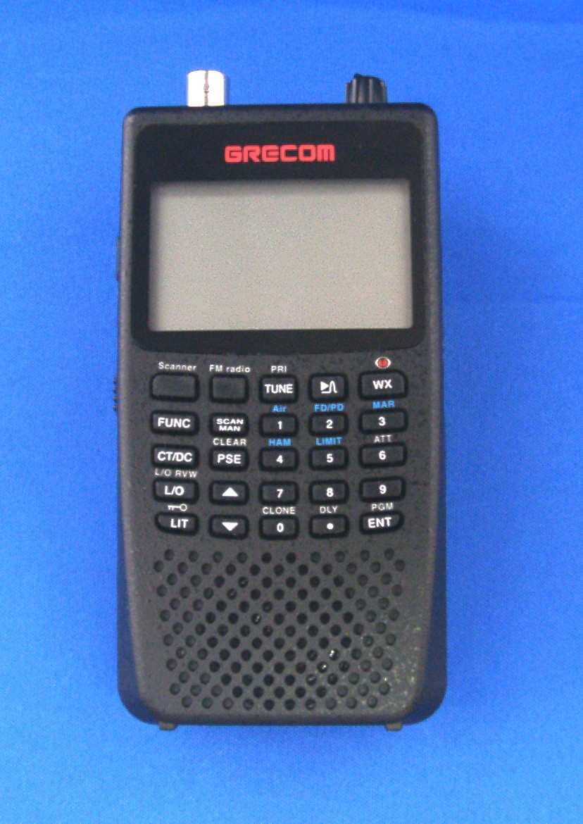
ADV0908900
Apr 03, 2012Scanning Receiver
Equipment Class
CSR - Scanning Receiver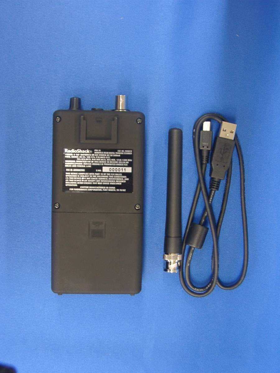
ADV0602903
Jan 27, 2011Scanning Receiver
Equipment Class
CSR - Scanning Receiver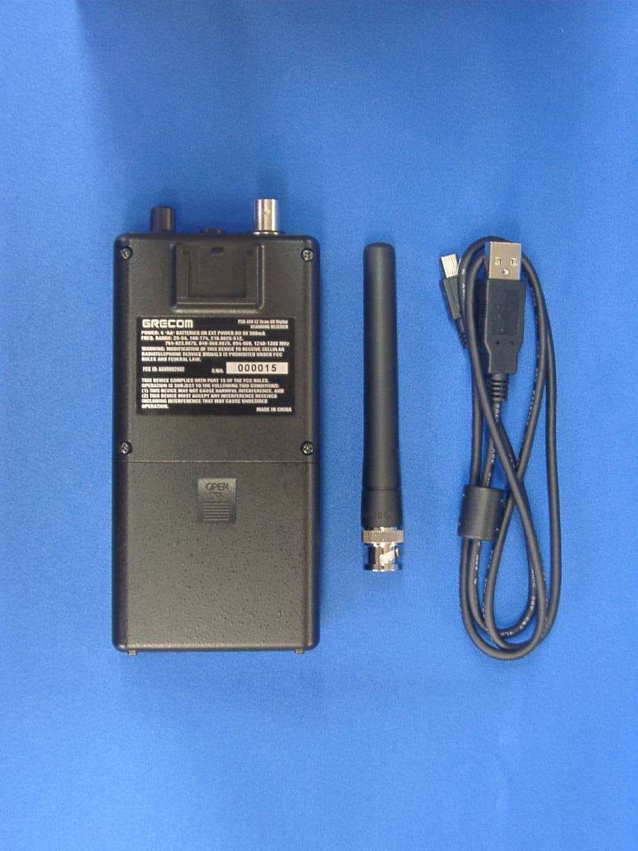
ADV0602902
Jan 27, 2011Scanning Receiver
Equipment Class
CSR - Scanning Receiver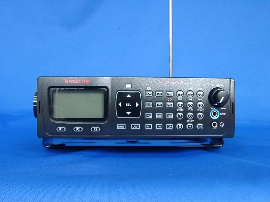
ADV0714902
Jan 16, 2011Radio Frequency Scanner
Equipment Class
CSR - Scanning Receiver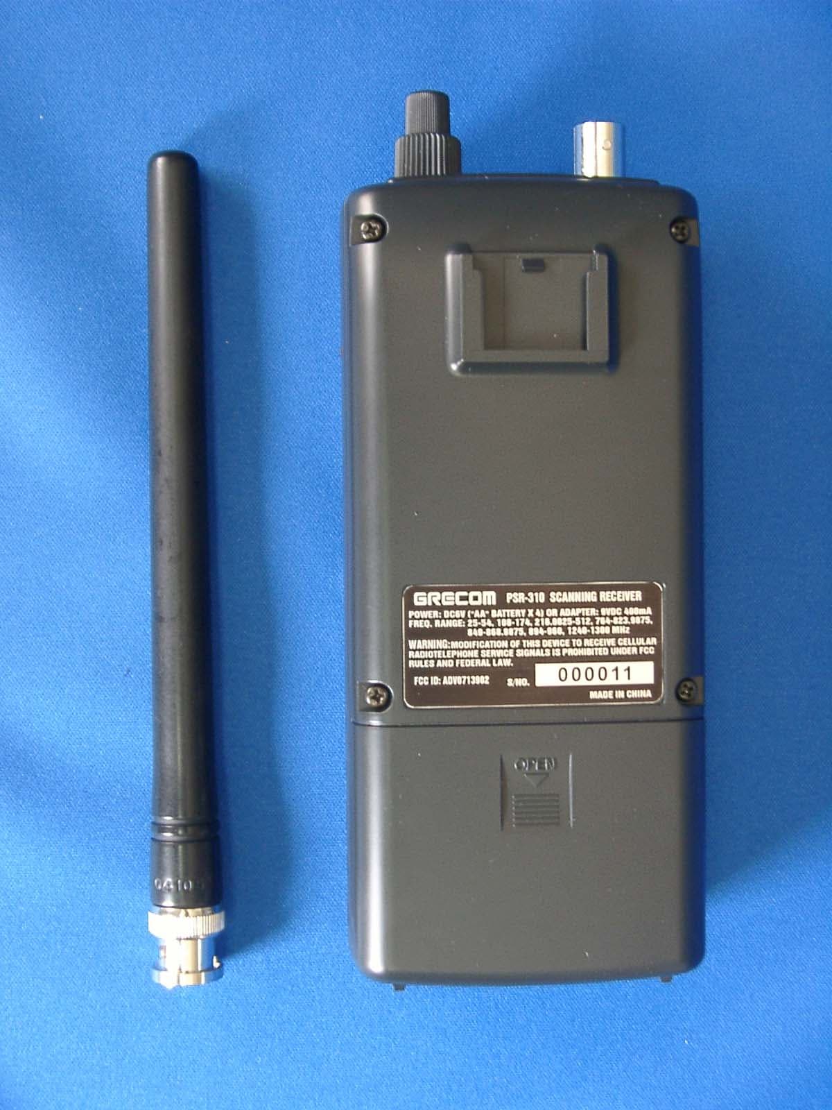
ADV0713902
Aug 12, 2010Radio Frequency Scanner
Equipment Class
CSR - Scanning Receiver