ADV2000428Scanning Receiver
General Research of Electronics Inc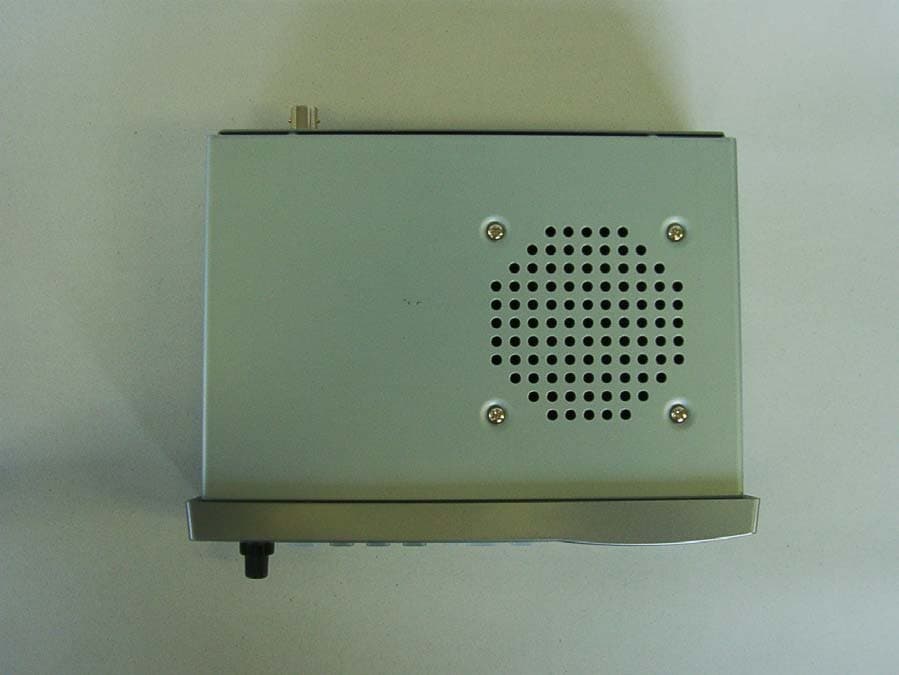
Click to zoom
Application Details
- Equipment Class
- CSR - Scanning Receiver
- Date of Grant
- Mar 28, 2005
- Application Purpose
- Original Equipment
- Date of Application
- Mar 28, 2005
- Equipment Note
- Scanning Receiver
- Frequency Range
- 894.00000000 - 960.00000000
- Country
- Japan
Documents & Files
Document Text
Text extracted from the exhibit documents filed with the FCC. Open a document above to read the original.
Users Manual
20-428 Owner’s Manual Page 1 of 50 RadioShack 20-428 PRO-2055 1,000 Channel Multi Trunking Mobile/Base Scanner Please read this user’s guide before installing, setting up and using your new product www.radioshack.com Thank you for purchasing your Pro-2055 multi trunking scanner from RadioShack. You can mount your scanner in a fixed position and use it as a base scanner or you can use it as a mobile scanner by mounting it in a vehicle. This scanner is one of a new generation of scanners designed to track Motorola® Type I and II (such as Smartnet® and Privacy Plus®) and hybrid analog trunking systems, GE-Ericsson (EDACS®) type systems, and EF Johnson (LTR) type systems which are extensively used in many communication systems. No additional hardware or add-on cards are needed. what’s included user’s guide quick start guide preloaded data addendum Scanner Antenna DC cable w/fuse AC adapter DIN sleeve and keys (2) Mounting bracket Knob (2) Rubber washer (2) Lock washer (2) Screw (2) Rubber foot (3) contents will add © 2005 RadioShack Corporation. All Rights Reserved. RadioShack, RadioShack.com, Hypersearch, Hyperscan, and Adaptaplug are trademarks used by RadioShack Corporation. Motorola, Smartnet, ASTRO and Privacy Plus are registered trademarks of Motorola Inc. EDACS is a registered trademark of MA-COM Inc. LTR is a registered trademark of EF Johnson. your scanner’s keypad TRUNK – stores the Trunking ID code or holds the trunking ID while scanning. 20-428 Owner’s Manual Page 2 of 50 L/OUT (Lock Out) – lets you lock out a selected channel, skip a specified frequency during search, or lock out a selected ID code. CLEAR – clears an incorrect entry. PROG (Program) – programs frequencies in channels PWR/VOL/SQ – long knob turns OFF/ON, and controls volume. Short knob controls squelch. PC/IF – connect an optional PC interface cable here to use the scanner with your computer. Headphone Symbol – attach headphones with 1/8” jack here. FUNC (Function) – lets you use various functions by pressing this key in combination with other keys. TUNE – press TUNE, PAUSE then /¥ or ¥/ to tune to a frequency. ATT (Attenuate) – turns attenuation on to reduce the scanner’s sensitivity and block extremely strong signals, or turns it off to return the sensitivity to normal. PAUSE – pauses search or tune operation. DIM – adjusts the backlight level (Light, Dark, or OFF). WX/(skywarn) – scans through the seven preprogrammed weather channels, or jumps to a Skywarn channel you programmed (997 – 999). PRI (Priority) – sets and turns the priority function on or off. TEXT – lets you input text. MODE – changes the receive mode (AM, FM, CT, DC, MO, ED, LT). SRCH (Search) – lets you search the seven search banks. SCAN/(stalker) – scans through the programmed channels, or activates the Signal Stalker II function. MAN (Manual) – stops scanning and lets you directly enter a channel number. /¥ or ¥/ – selects the scan or search direction. Number keys – Press to enter a number or a character (in text mode). /DELAY – enters a decimal point (necessary when programming frequencies), space, or programs delay time for the selected channel/search bank, or enters a hyphen (in trunking ID setting). ENT (Enter) – completes the entry of frequencies and text. your scanner’s rear view ANT – connect the supplied antenna or an external antenna here. SCREW HOLE – use to mount the scanner in a car with some hardware (screw not supplied). RESET – press to reset your scanner. DC 13.8V – connect a power source here. EXT SP – connect an external speaker here. your scanner’s display will add 20-428 Owner’s Manual Page 3 of 50 install your scanner You can mount your multi Trunking scanner in your vehicle, install it for mobility, or install it as a base station. mounting your scanner in your dashboard If you are unsure about how to install your scanner in your vehicle, consult your automobile manufacturer, dealer, or a qualified installer. Before installing, confirm your scanner fits in the desired mounting area and you have all the necessary materials. Your scanner requires a 2 x 7 1/8 x 5 5/16 inch (50 x 180 x 135 mm) mounting area. 1. Remove the four rear screws and pull off the black case before installing your scanner. 2. Install the DIN sleeve into the opening in your dashboard, lip facing out. 3. Push out the top and bottom tabs to hold the sleeve firmly in place. 4. Slide the scanner into the sleeve until it locks in place. Notes: To remove your scanner from the DIN sleeve, insert the two keys straight into the scanner’s front panel. Then, remove the scanner by pulling front panel. When mounting in your dashboard, you will need to connect an external antenna and an external speaker. mobile mounting in your vehicle You can mount your scanner under the dashboard, or on top of it, using the mounting bracket. 1. Attach the three protective rubber feet to the mounting bracket when you use the scanner on a flat surface. Do not use them when you mount the bracket with screws. 2. Use the supplied mounting bracket as a template to mark positions for the two mounting screws. 3. At the marked positions, drill holes slightly smaller than the screws. 4. Remove the paper backing from each washer and stick one inside of each bracket’s ear, aligning the washer’s hole with the bracket’s hole. 5. Attach the mounting bracket to your vehicle’s surface using the supplied screws and lockwashers. 20-428 Owner’s Manual Page 4 of 50 6. Slide the scanner into the bracket, aligning the scanner’s holes with the holes in the bracket, and then screw the mounting knobs into the scanner. Note: When drilling holes, be sure to avoid obstructions behind the mounting surface. Consult a qualified installer if in doubt. using your scanner as a base station You can place your scanner on a desk, shelf, or table to use it as a base station. Since the speaker is on the bottom of the scanner, you may want to use the mounting bracket to elevate your scanner off the surface for better sou…
Text truncated - open the document above for the full version.
External Photos
Model Number: PRO-2055 FCC ID:ADV2000428 Model Number: PRO-2055 FCC ID:ADV2000428 Model Number: PRO-2055 FCC ID:ADV2000428 Model Number: PRO-2055 FCC ID:ADV2000428 Model Number: PRO-2055 FCC ID:ADV2000428 Model Number: PRO-2055 FCC ID:ADV2000428 Model Number: PRO-2055 FCC ID:ADV2000428 Model Number: PRO-2055 FCC ID:ADV2000428 Model Number: PRO-2055 FCC ID:ADV2000428 Model Number: PRO-2055 FCC ID:ADV2000428
Test Report
EMC Report for General Research of Electronics, Inc.on the model PRO-2055 File: 30740191 Page 1 of 21 TEST REPORT Report Number: 30740191 Project Number: 3074019 March 25, 2005 Testing performed on the Multi Trunk-Tracking Handheld Scanner Model Number: PRO-2055 FCC ID: ADV2000428 to FCC Part 15, Subpart B ICES 003 Class: B For General Research of Electronics, Inc. A2LA Certificate Number: 1755-01 Test Performed by: Test Authorized by: Intertek 1365 Adams Court Menlo Park, CA 94025 General Research of Electronics, Inc. 425 Harbor Blvd. Suit B Belmont, CA 94002 Prepared by: Date: March 25, 2005 Bruce Gordon Reviewed by: Date: March 25, 2005 Ollie Moyrong This report is for the exclusive use of Intertek's Client and is provided pursuant to the agreement between Intertek and its Client. Intertek's responsibility and liability are limited to the terms and conditions of the agreement. Intertek assumes no liability to any party, other than to the Client in accordance with the agreement, for any loss, expense or damage occasioned by the use of this report. Only the Client is authorized to copy or distribute this report and then only in its entirety. Any use of the Intertek name or one of its marks for the sale or advertisement of the tested material, product or service must first be approved in writing by Intertek. The observations and test results in this report are relevant only to the sample tested. This report by itself does not imply that the material, product, or service is or has ever been under an Intertek certification program. This report must not be used to claim product endorsement by A2LA, NIST nor any other agency of the U.S. Government. EMC Report for General Research of Electronics, Inc.on the model PRO-2055 File: 30740191 Page 2 of 21 VERIFICATION OF COMPLIANCE Report No. 30740191 Verification is hereby issued to the named APPLICANT and is VALID ONLY for the equipment identified hereon for use under the rules and regulations listed below. Equipment Under Test: Multi Trunk-Tracking Scanner Trade Name: General Research of Electronics, Inc. Model No.: PRO-2055 Applicant: General Research of Electronics, Inc. Contact: Mr. Teru Takahashi Address: 425 Harbor Blvd. Suite B Belmont, CA 94002 Country USA Tel. number: 650-591-1400 Fax number: 650-591-2001 Applicable Regulation: FCC Part 15, Subpart B Industry Canada ICES-003 Equipment Class: Class B Date of Test: March 19, 2005 We attest to the accuracy of this report: Date: Bruce Gordon Test Engineer Ollie Moyrong EMC Department Manager EMC Report for General Research of Electronics, Inc.on the model PRO-2055 File: 30740191 Page 3 of 21 TABLE OF CONTENTS 1.0 General Description ........................................................................................................ 4 1.1....... Product Description ........................................................................................................ 4 1.2....... Related Submittal(s) Grants ............................................................................................ 4 1.3....... Test Methodology ........................................................................................................... 4 1.4....... Test Facility .................................................................................................................... 4 1.5....... Summary of Test Results ................................................................................................ 5 2.0 System Test Configuration............................................................................................. 6 2.1....... Justification ..................................................................................................................... 6 2.2....... EUT Exercising Software ............................................................................................... 6 2.3....... Mode of Operation.......................................................................................................... 6 2.4....... Support Equipment List and Description........................................................................ 7 2.5....... Equipment Setup Block Diagram ................................................................................... 7 2.6....... Equipment Modification ................................................................................................. 7 3.0 Emission Test Results ..................................................................................................... 8 3.1....... Field Strength Calculation .............................................................................................. 9 3.2....... Radiated Emission Data ................................................................................................ 10 3.3....... AC Line Conducted Emission Data .............................................................................. 12 3.4....... Antenna Conducted Emission Data .............................................................................. 15 4.0 List of Test Equipment ................................................................................................. 18 Appendix A – EUT Specification............................................................................................. 19 Appendix B – Local Oscillator Frequency calculation .......................................................... 20 Appendix C – Antenna Drawing ............................................................................................. 21 EMC Report for General Research of Electronics, Inc.on the model PRO-2055 File: 30740191 Page 4 of 21 1.0 General Description 1.1 Product Description The Equipment under Test (EUT) is Multi Trunk-Tracking Scanning Receiver, model PRO-2055. Please refer to the attached specifications sheets in Appendix A for more details. A pre-production version of the sample was received on March 14, 2005 in good condition. As declared by the Applicant, it is identical t…
Text truncated - open the document above for the full version.
Test Setup Photos
Model Number: PRO-2055 FCC ID:ADV2000428 Radiated Emissions Model Number: PRO-2055 FCC ID:ADV2000428 Radiated Emissions Model Number: PRO-2055 FCC ID:ADV2000428 Radiated Emissions Model Number: PRO-2055 FCC ID:ADV2000428 Radiated Emissions Model Number: PRO-2055 FCC ID:ADV2000428 AC Line Conducted Emissions Model Number: PRO-2055 FCC ID:ADV2000428 AC Line Conducted Emissions
Contact Information
Applicant
Sadanori Shitara(Director of Engineering and Development)
Technical Contact
Intertek Testing Services NA Inc.Ollie Moyrong
[email protected]650-463-2900
1365 Adams Court · Menlo Park, California · United States
Non-Technical Contact
Intertek Testing Services NA Inc.Ollie Moyrong
[email protected]650-463-2900
Test Firm
Intertek Testing Services NA Inc.John Quigley
Technical Specifications
| # | Rule Parts | Frequency Range | Power Output |
|---|---|---|---|
| 9 | 15B | 894 MHz - 960 MHz | - |
Other Applications from General Research of Electronics Inc
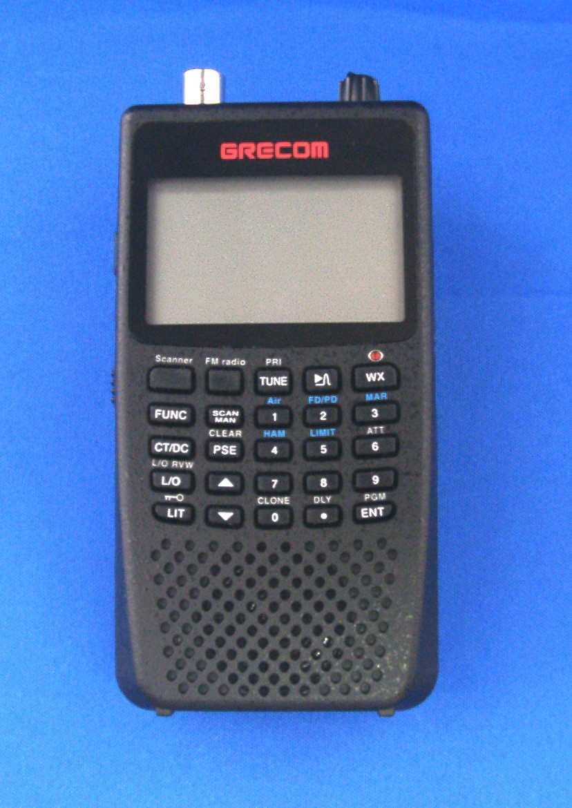
ADV0908900
Apr 03, 2012Scanning Receiver
Equipment Class
CSR - Scanning Receiver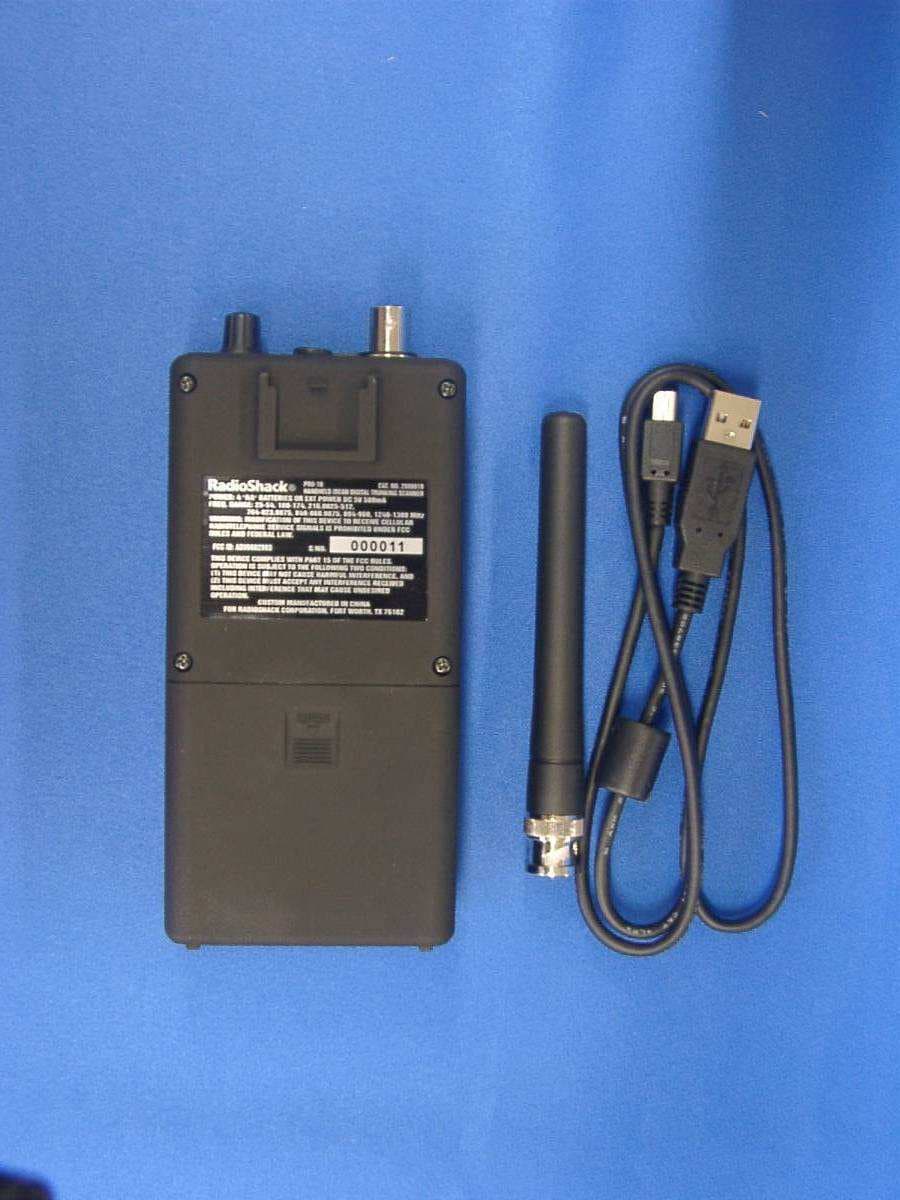
ADV0602903
Jan 27, 2011Scanning Receiver
Equipment Class
CSR - Scanning Receiver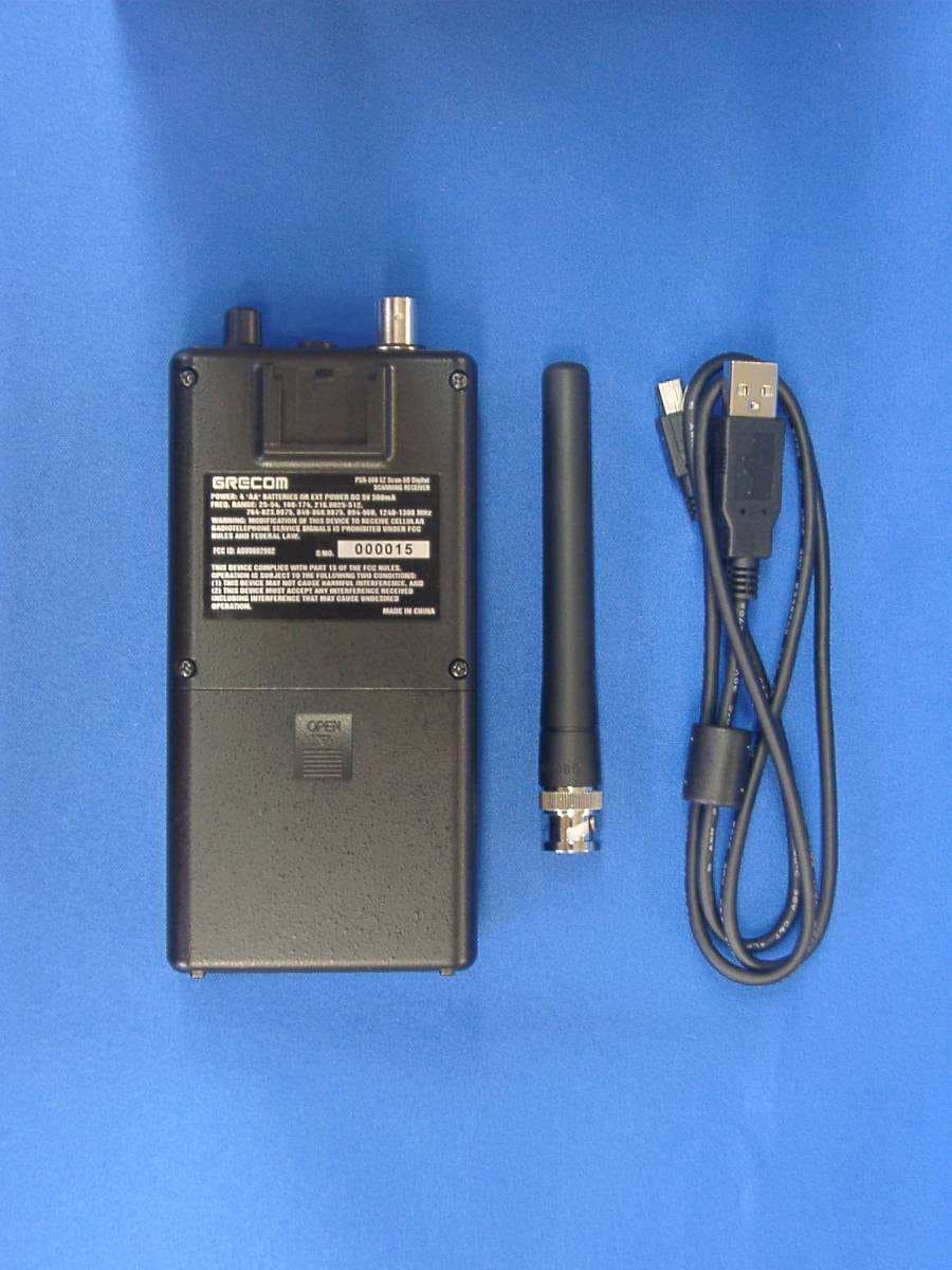
ADV0602902
Jan 27, 2011Scanning Receiver
Equipment Class
CSR - Scanning Receiver
ADV0714902
Jan 16, 2011Radio Frequency Scanner
Equipment Class
CSR - Scanning Receiver
ADV0713902
Aug 12, 2010Radio Frequency Scanner
Equipment Class
CSR - Scanning Receiver