AEKA02849RR/C Receiver - The Typhoon
Taiyo Co., Ltd.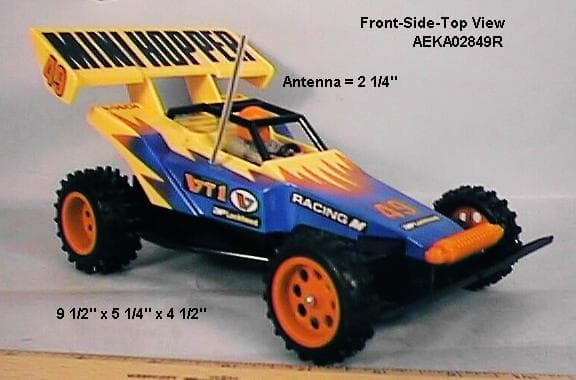
Click to zoom
Application Details
- Equipment Class
- CYY - Communications Receiver used w/Pt 15 Transmitter
- Date of Grant
- Sep 11, 2000
- Application Purpose
- Original Equipment
- Date of Application
- Sep 11, 2000
- Equipment Note
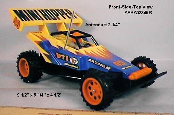
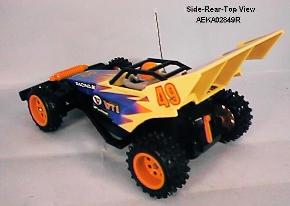
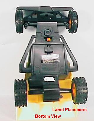
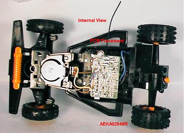
- R/C Receiver - The Typhoon
- Frequency Range
- 49.82000000 - 49.90000000
- Company
- Taiyo Co., Ltd.
- Country
- Japan
Documents & Files
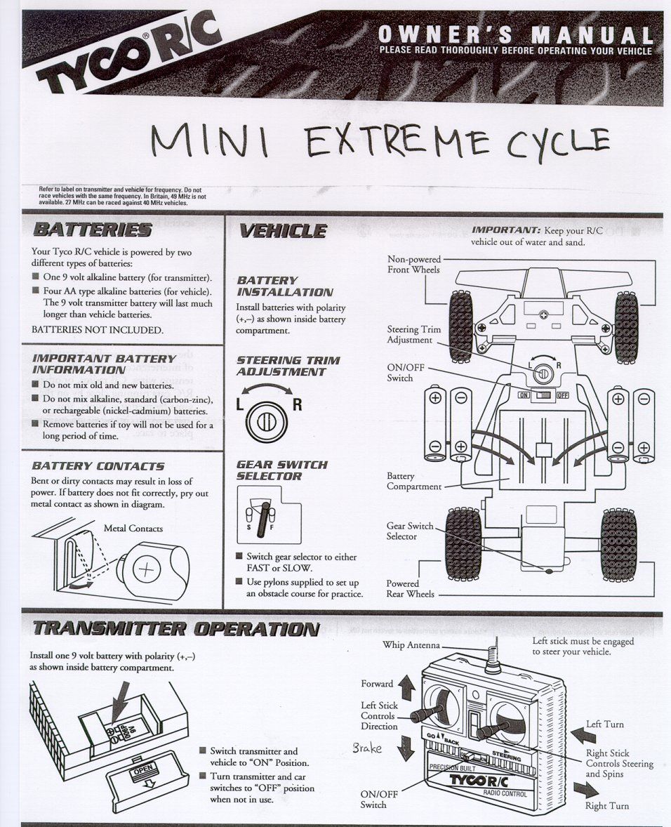
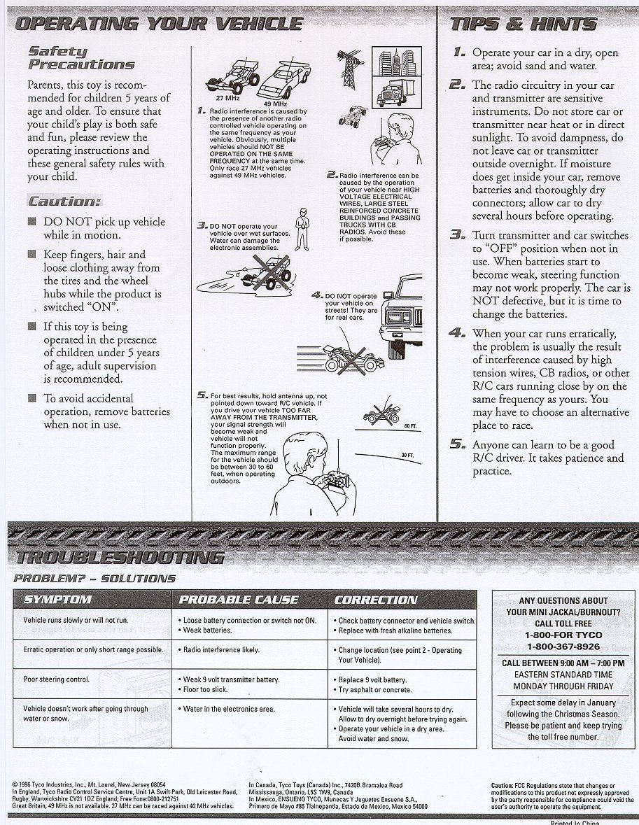
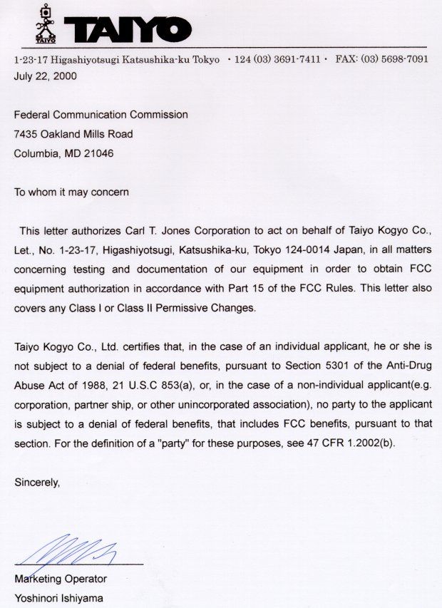
Document Text
Text extracted from the exhibit documents filed with the FCC. Open a document above to read the original.
Attestation Statements
STATEMENT OF MICHAEL A. NICOLAY In Connection With APPLICATION FOR CERTIFICATION THE MINI HOPPER R/C RECEIVER FCC ID: AEKA02849R I am an Engineer, an employee in the firm of Carl T. Jones Corporation, with offices located in Springfield, Virginia. My education and experience are a matter of record with the Federal Communications Commission. All of the measurements contained in this test report were performed by me or under my supervision, and I attest to the accuracy of each. I submit that, to the best of my knowledge, the test sample meets the technical standards set forth in the Commission's Rules and Regulations. DATED: September 6, 2000 Michael A. Nicolay Carl T. Jones Corporation 7901 Yarnwood Court Springfield, Virginia, 22304 (703) 569-7704 [email protected]
Operational Description
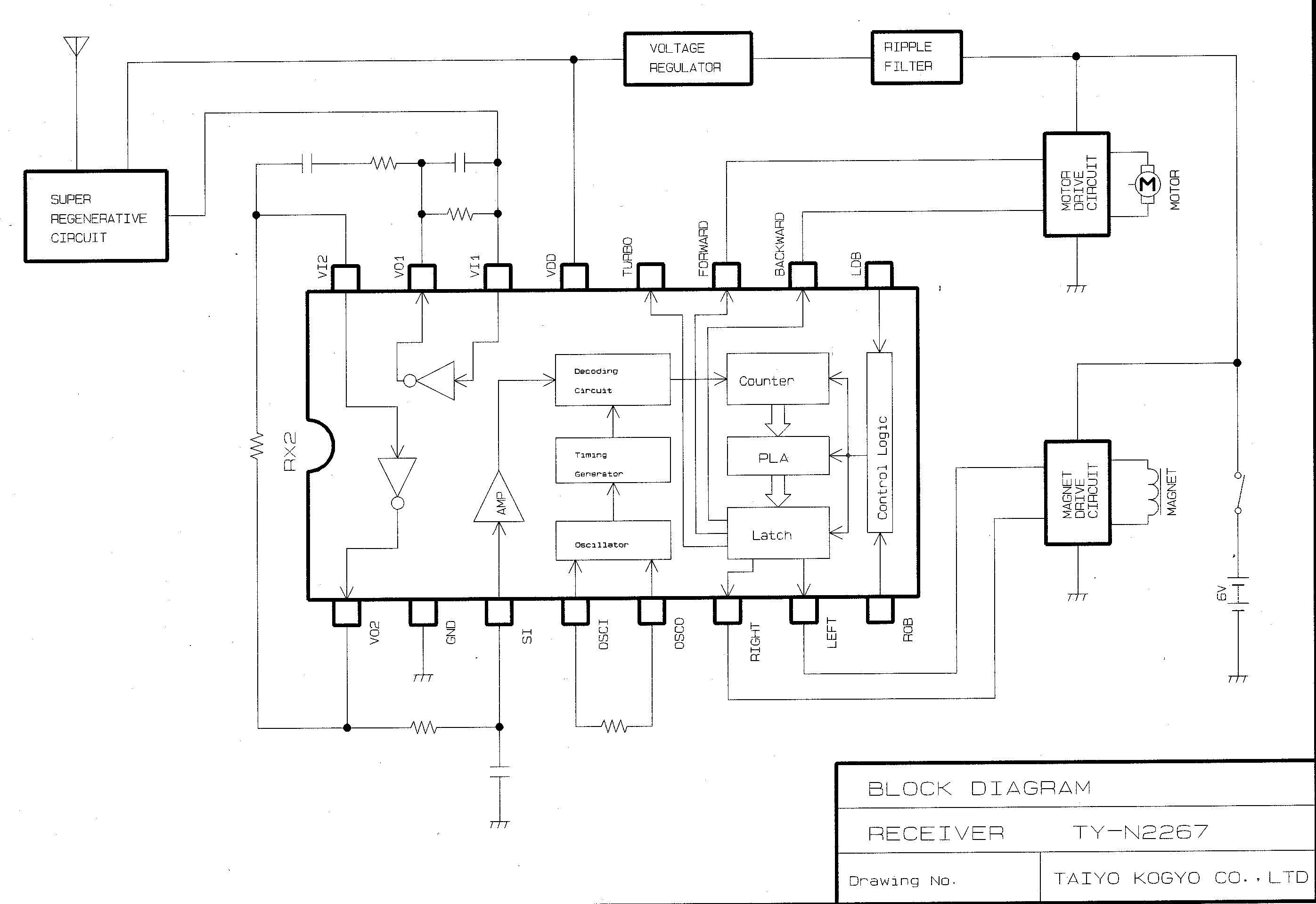
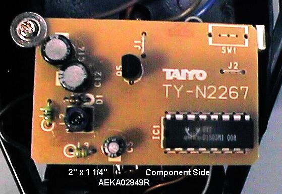
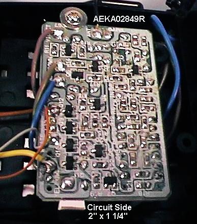
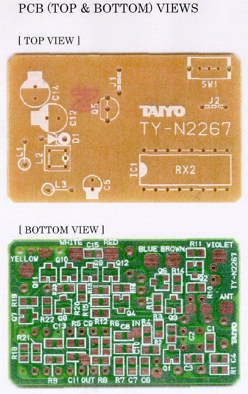
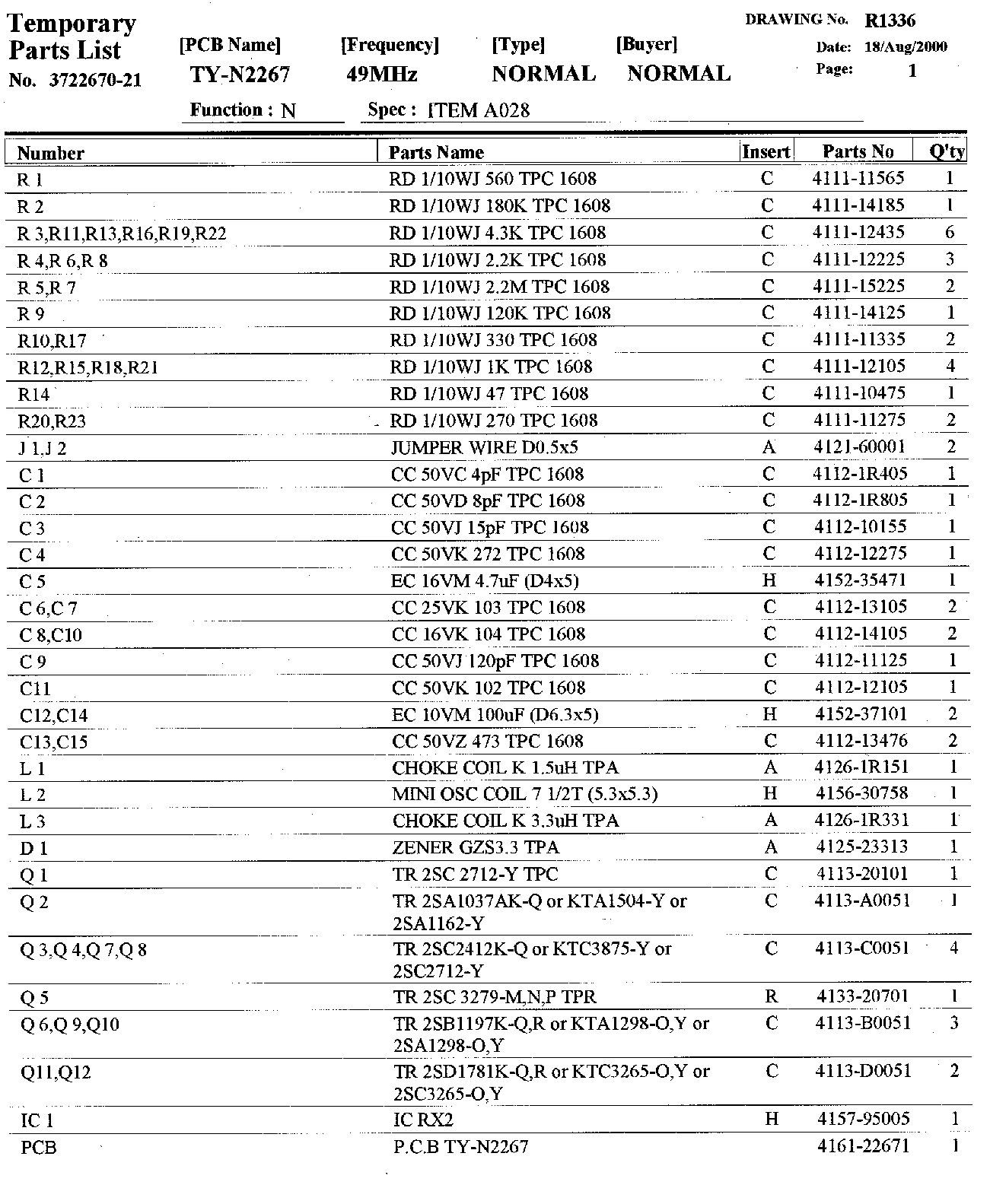
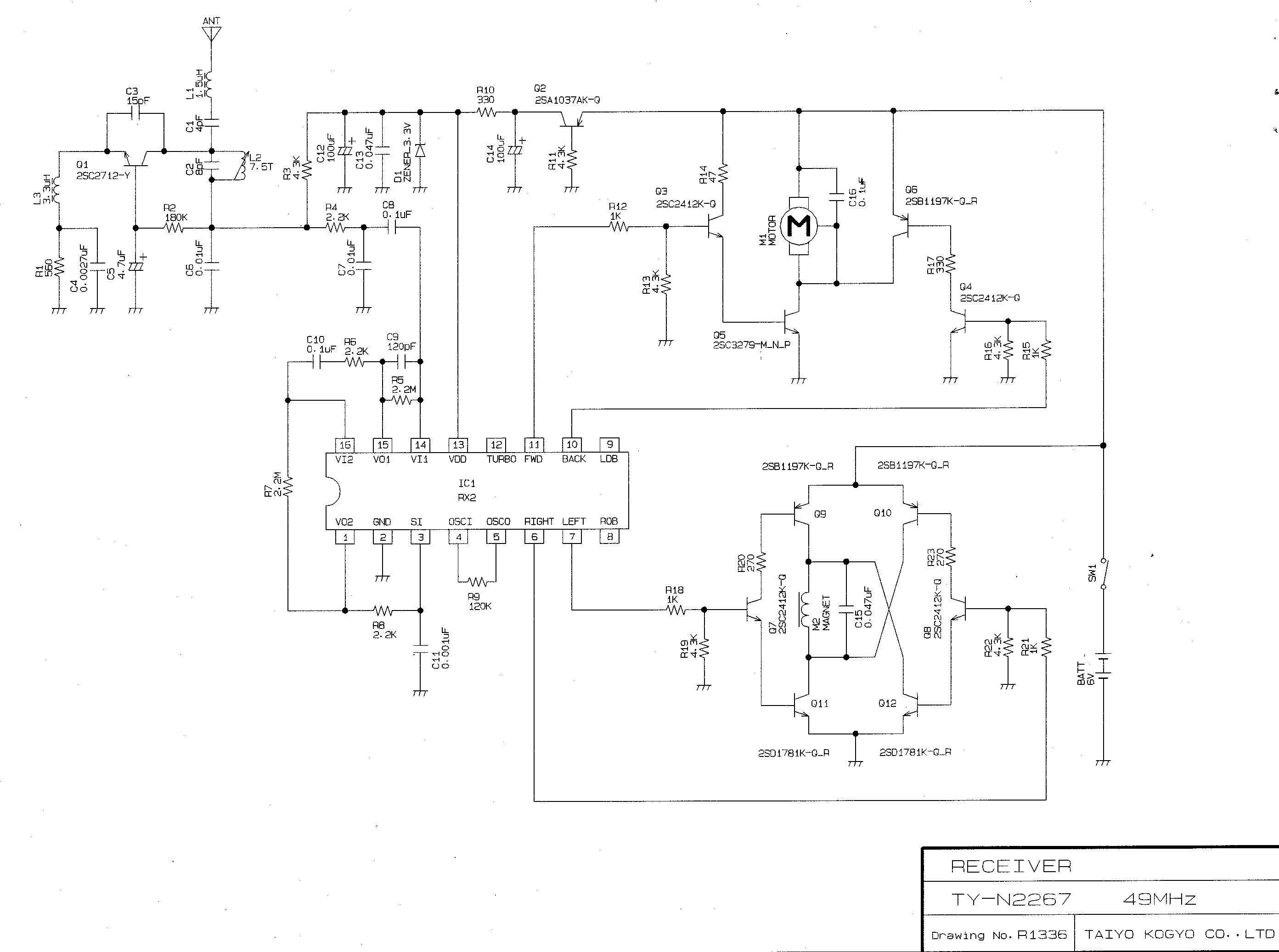
EXPOSITORY STATEMENT/DESCRIPTION FCC ID:AEKA02849R - Mini Hopper The relaxation oscillator receives the RF signal from its associated transmitter then detects and conditions the motor control signals and subsequently supplies these digital control signals to the motor drive circuits for controlling the movements of the receiver. The motor drive circuits consist of Q3, Q5, and Q6 for one motor - M1. Q7 Q8, and Q11 do not control a drive motor, these transistors act as a “break” to stop the R/C when the transmitter control is in the “Back” position. The superregenerative receiver’s RF section is comprised of the superregenerator relaxation oscillator circuit, which consists Q1, and its associated passive components, and the LSI chip, IC1, RX2 . The detected digital control signals are generated within IC1 and are then delivered to the motor, M1, or the “break” function, controlling the movements of the R/C vehicle. The receiver is powered by four 1.5 VDC batteries, not supplied with the device. No external grounding is used or required. The only tuning required is to tune the relaxation oscillator, L1, to receive the RF signal from its associated transmitter, and is performed at the manufacturing facility by qualified technicians.
Test Report
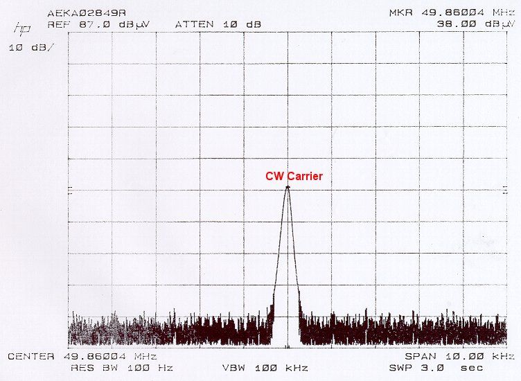
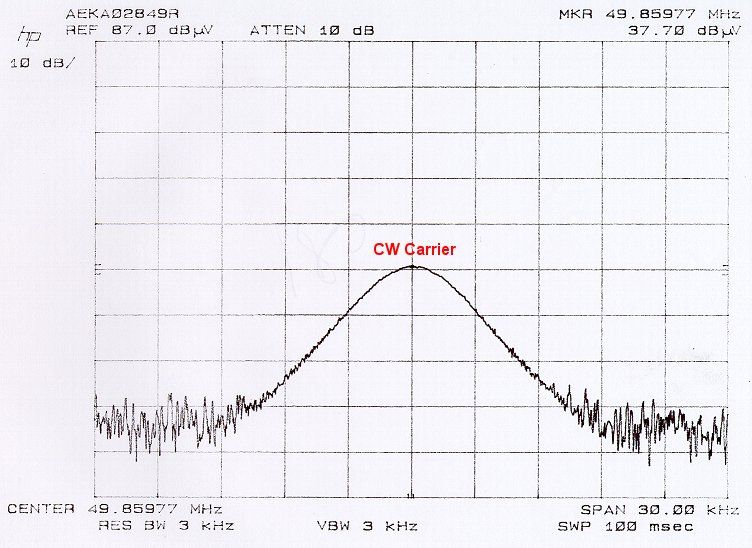
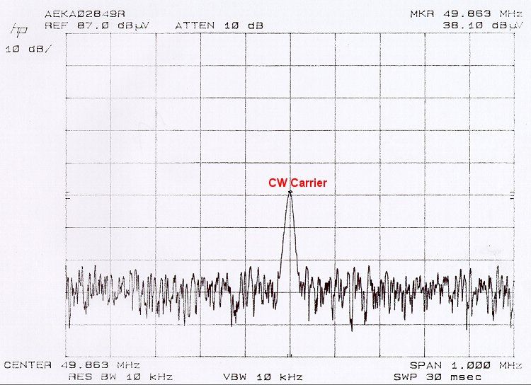
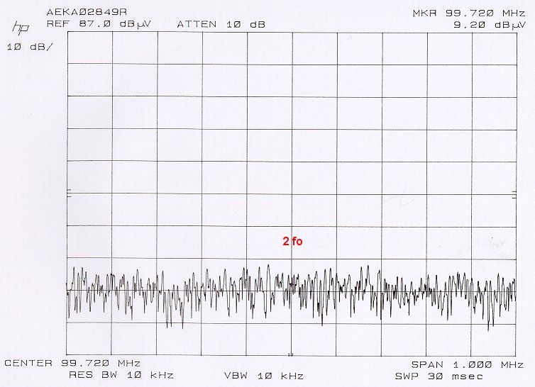
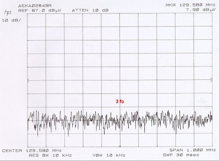
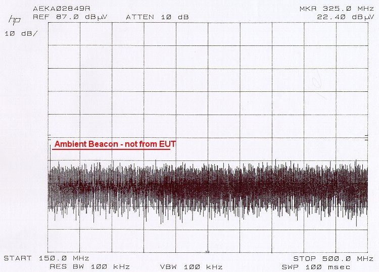
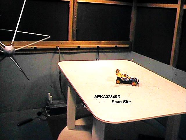
TABLE 1 FIELD STRENGTH RADIATED EMISSIONS DATA SHEET ANTENNA FACTORFCC EMISSIONANTENNAEMISSIONANDEMISSIONLIMIT FREQUENCY POLARITYLEVELCABLE LOSSLEVEL(3 METERS) (MHZ)(H,V)(dBuV)(dB)(dBuV/m)(dBuV/m) Note: No detectable emissions were observed during the 1 meter scan, therefore the EUT was not taken to the open-area-test-site. See attached spectral plots. CLIENT:TAIYO KOGYO FCC ID:AEKA02849R MODEL:The Typhoon TEST DATE:08/06/00 TEST ENGINEER:Michael A. Nicolay
Contact Information
Applicant
Hiroyuki Sasaki(Manager of Quality Assurance Section)
Test Firm
Carl T. Jones CorporationCarl Jones
Technical Specifications
| # | Rule Parts | Frequency Range | Power Output |
|---|---|---|---|
| 1 | 15B | 49.82 MHz - 49.9 MHz | - |
Other Applications from Taiyo Co., Ltd.
AEKA54095
Oct 14, 2007REMOTE CONTROL TRANSMITTER
Equipment Class
TNB - Licensed Non-Broadcast Station Transmitter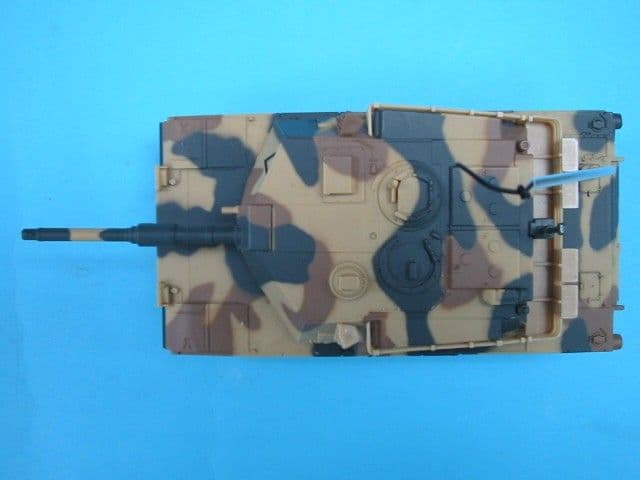
AEKA73049R
Sep 04, 2007BATTLE TANK
Equipment Class
CRR - Superregenerative Receiver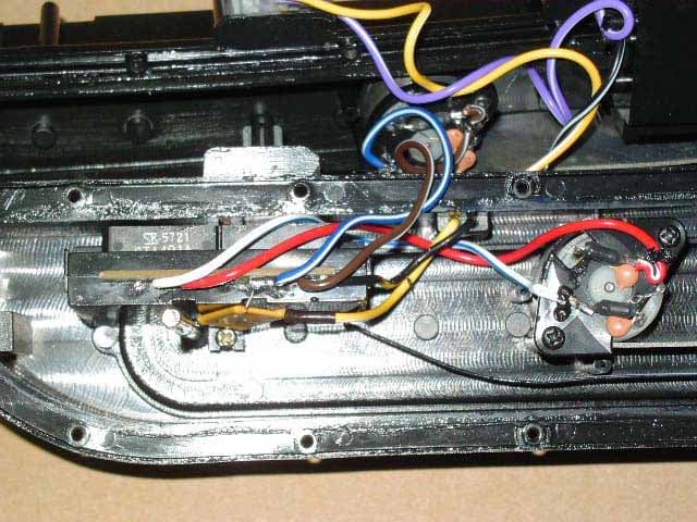
AEKA56349R
Dec 10, 200649MHz RECEIVER
Equipment Class
CRR - Superregenerative Receiver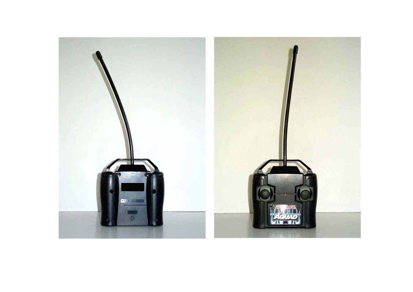
AEKA56327
Dec 06, 200627 MHz TRANSMITTER
Equipment Class
DXX - Part 15 Low Power Communication Device Transmitter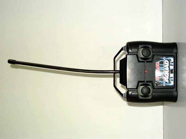
AEKA56349
Dec 06, 200649MHz TRANSMITTER
Equipment Class
DXX - Part 15 Low Power Communication Device Transmitter