AEKA1422727MHz Remote Control Transmitter
Taiyo Co., Ltd.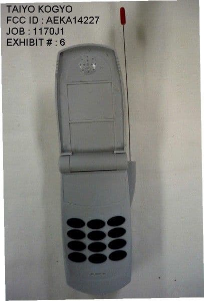
Click to zoom
Application Details
- Equipment Class
- DXX - Part 15 Low Power Communication Device Transmitter
- Date of Grant
- Dec 17, 2001
- Application Purpose
- Original Equipment
- Date of Application
- Dec 17, 2001
- Equipment Note
- 27MHz Remote Control Transmitter
- Frequency Range
- 26.96000000 - 27.28000000
- Company
- Taiyo Co., Ltd.
- Country
- Japan
Documents & Files
Document Text
Text extracted from the exhibit documents filed with the FCC. Open a document above to read the original.
Users Manual
SAVE THESE INSTRUCTIONS FOR FUTURE REFERENCE. THEY CONTAIN IMPORTANT INFORMATION. Important! Please read your Owner's Manual all the way through before operating your vehicle. Safety First • Drive your vehicle in a safe area away from people, pets, cars, etc. Not in streets, in or near water, or in darkness! • Don't touch or try to pick up vehicle when it is in motion. Wait until it stops completely. • Keep hair, fingers, face and loose clothing away from wheels while the vehicle is switched on or while the remote is operating. • Be a responsible Cell Racer™ R/C operator! Batteries Required (not included) 2 "AA" Alkaline batteries required for vehicle. One 9-Volt Alkaline battery required for the remote. READ AND FOLLOW ALL INSTRUCTIONS IMPORTANT BATTERY SAFETY INFORMATION CAUTION: TO AVOID BATTERY LEAKAGE • Make sure the batteries are inserted with the correct polarity and follow the toy and battery manufacturers' instructions. • Do not mix old and new batteries. • Do not mix alkaline, standard (carbon-zinc), or rechargeable (nickel-cadmium or nickel-metal hydride) batteries. • Remove weak or exhausted batteries from the product. ADDITIONAL IMPORTANT BATTERY SAFETY INFORMATION • An adult should help with battery replacement • Only batteries of the same or equivalent type as recommended in the "Battery Installation" (or replacement) instructions are to be used. • Non-rechargeable batteries are not to be recharged. • If removable rechargeable batteries are used, they are only to be charged under adult supervision. • Rechargeable batteries are to be removed from the product before they are charged. • If you use a battery charger, it should be examined regularly for damage to the cord, plug, enclosure and other parts. Do not use a damaged battery charger until it has been properly repaired. • Dispose of batteries safely and properly. R/C Facts for Improved Operation 1. When batteries start to discharge, vehicle may slow, stop, or refuse to respond to your control. It's time to replace both vehicle batteries and/or remote battery. This is absolutely the #1 cause of all problems and questions! Observe polarity when replacing batteries. 2. Radio frequency interference can interfere with the control of your vehicle. Buildings, power wires, other R/C remotes, or CB radio can all cause problems. Pick a place to drive that's away from these things. 3. Hold remote so antenna points up, not toward the vehicle. Keep vehicle within range (about 30 to 40 feet) to keep control. If vehicle goes out of range, try lifting remote high into air to increase range. 4. Wipe vehicle clean and dry after each use, including inside battery compartments. 5. Turn vehicle power switch off immediately after running. Remove batteries for storing or shipping. Keep vehicle and Remote away from heat and direct sunlight and moisture. 6. Do not run vehicle in or near water. Troubleshooting Guide Don't take your vehicle back to the store--try solving problems using this valuable guide. COMPLIANCE WITH FCC REGULATIONS THIS DEVICE COMPLIES WITH PART 15 OF FCC RULES. OPERATION OF THIS DEVICE IS SUBJECT TO THE FOLLOWING TWO CONDITIONS: (1) THIS DEVICE MAY NOT CAUSE HARMFUL INTERFERENCE. (2) THIS DEVICE MUST ACCEPT ANY HARMFUL INTERFERENCE THAT MAY CAUSE UNDESIRED OPERATION. This device generates and uses radio frequency energy and if not used properly may cause interference to radio and television reception. It has been tested and found to comply with the limits set by the FCC, which are designed to provide reasonable protection against such interference. CAUTION: FCC Regulations state that changes or modifications to this product not expressly approved by the party responsible for compliance could void the user's authority to operate the equipment . PRINTED IN CHINA © 2001 Taiyo Edge Ltd. Co., P.O. Box 1470, New Smyrna Beach, FL 32170, U.S.A. All Rights Reserved. U.S. and Foreign Patents Pending.Taiyo Edge; Get the Edge!; On Road, Off-Road, No Road!; and Cell Racer are licensed trademarks of Tilbor Marketing and Development Inc. Product specifications subject to change. Product may differ from illustrations. TM Taiyo Edge™ R/C Consumer Service We want to assist you! DO NOT RETURN THE PRODUCT TO THE STORE! Log on: Click “Help/Service” at www.taiyoedge.com E-mail: [email protected] 90-DAY LIMITED WARRANTY (a copy of this warranty is inside) TOLL-FREE CONSUMER HELPLINE NUMBER 1-866-4-EDGE-RC (1-866-433-4372) ™ Problem Probable Cause Correction Vehicle runs slowly, or • Batteries dead or low charge • Install 2 fresh new "AA" alkaline cells won't move, or won't steer • Batteries installed incorrectly • Remove and replace batteries, making in remote or vehicle sure battery direction (polarity, +/-) is • Loose battery connection correct and battery compartment contacts, • Dirty battery or battery plug and socket are clean. compartment contacts • Replace remote battery. • Power switch is off • Turn on Power switch. Erratic operation, loss of • Radio interference • Move to another location. control, short range • Loose or curled • Extend antenna fully. Point up in the air, remote antenna not at vehicle. • Antenna touching hands • Don't touch antenna during operation. or body • Replace both vehicle batteries and / or • Weak remote battery remote battery • Weak vehicle batteries Vehicle stops working after • Water in battery, electronics • Any time vehicle is run through water, going through water, mud or motor areas turn power knob off IMMEDIATELY, or snow remove batteries, dry inside and out with clean soft cloth and allow to dry overnight with battery door open. Always avoid wet surfaces, puddles or rain. Vehicle Battery Installation 1. Slide vehicle BATTERY DOOR open and remove as shown. (Fig. 1) 2. Insert 2 fresh, new Alkaline batteries into battery compartment as shown. IMPORTANT: OBSERVE BATTERY POLARITY (DIRECTION, + AND -). (Fig. 2) 3. Replace BATTERY DOOR and slide closed until it latches. (Fig. 3) Remote Battery Installation 1.…
Text truncated - open the document above for the full version.
Operational Description
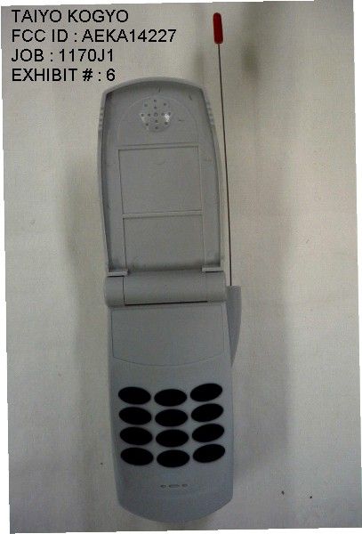
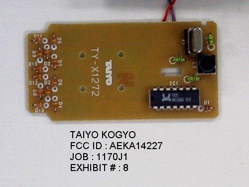
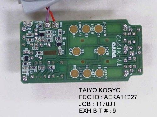
Circuit description for TAIYO KOGYO transmitter Switches S1 thru 8 activate IC1 the encoder integrated circuit used as the modulation of the RF carrier. The RF carrier is formed by Q1 and crystal X1. Q2 is the oscillator buffer/ RF amplifier transistor. C7, C8, L3, and L4 act as the antenna matching network and harmonic suppression. Energy is supplied by a 9V battery. The antenna and ground system consist of a short piano wire 6 inches in length. The unit has no external ground connection. The pcb board traces are the only ground. TAIYO KOGYO CO LTD FCC ID : AEKA14227 JOB : 1170J1 EXHIBIT # : 10
Test Report
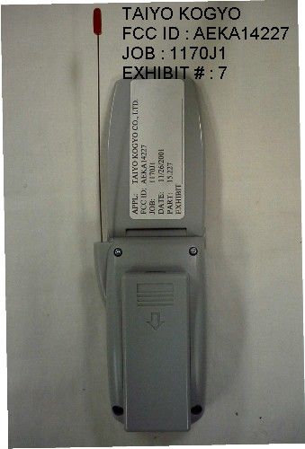
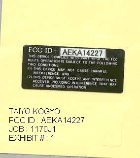
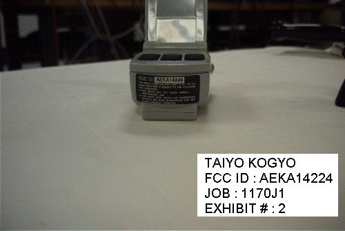
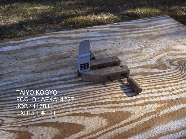
TABLE OF CONTENTS APPLICANT: TAIYO KOGYO CO., LTD. FCC ID: AEKA14227 TEST REPORT CONTAINING: PAGE 1......TEST EQUIPMENT LIST PAGE 2......TEST PROCEDURES PAGE 3......RADIATION INTERFERENCE TEST DATA PAGE 4......OCCUPIED BANDWIDTH TEST DATA PAGE 5......OCCUPIED BANDWIDTH PLOT EXHIBITS CONTAINING: EXHIBIT 1............FCC ID LABEL SAMPLE EXHIBIT 2............SKETCH OF LABEL LOCATION EXHIBIT 3............BLOCK DIAGRAM EXHIBIT 4............SCHEMATIC EXHIBIT 5............USERS MANUAL EXHIBIT 6............EXTERNAL PHOTO - FRONT VIEW EXHIBIT 7............EXTERNAL PHOTO – REAR VIEW EXHIBIT 8............INTERNAL PHOTO - COMPONENT VIEW EXHIBIT 9............INTERNAL PHOTO - COPPER VIEW EXHIBIT 10...........CIRCUIT DESCRIPTION EXHIBIT 11...........TEST SET UP PHOTO APPLICANT: TAIYO KOGYO CO., LTD. FCC ID: AEKA14227 REPORT #: T\TAIYO\1170J1\1170J1RPT.doc PAGE: TABLE OF CONTENTS LIST APPLICANT: TAIYO KOGYO CO., LTD. FCC ID: AEKA14227 TEST EQUIPMENT LIST 1. X Spectrum Analyzer: HP 8566B-Opt 462, S/N 3138A07786, w/ preselector HP 85685A, S/N 3221A01400, Quasi-Peak Adapter HP 8565OA, S/N 3303A01690 & Preamplifier HP 8449B-OPT H02, S/N 3008A00372 Cal. 8/31/01 Due 8/31/02 2. X Biconnical Antenna: Eaton Model 94455-1, S/N 1057, Cal. 10/1/01 Due 10/1/02 3. Biconnical Antenna: Electro-Metrics Model BIA-25, S/N 1171 Cal. 4/26/01 Due 4/26/03 4. Log-Periodic Antenna: Electro-Metrics Model EM-6950, S/N 632 Char. 3/15/00 Due 3/15/01 5. X Log-Periodic Antenna: Electro-Metrics Model LPA-30, S/N 409 Char. 3/15/00 Due 3/15/01 6. Double-Ridged Horn Antenna: Electro-Metrics Model RGA-180, 1-18 GHz, S/N 2319 Cal. 4/27/99 Due 4/27/00 7. 18-26.3GHz Systron Donner Standard Gain Horn #DBE-520-20 No Cal Required 8. Horn 40-60GHz: ATM Part #19-443-6R No Cal Required 9. Line Impedance Stabilization Network: Electro-Metrics Model EM-7820, w/NEMA Adapter S/N 2682 Cal. 3/16/01 Due 3/16/02 10. Temperature Chamber: Tenney Engineering Model TTRC, S/N 11717-7 Char. 1/27/01 Due 1/27/02 11. Frequency Counter: HP Model 5385A, S/N 3242A07460 Char. 11/20/00 Due 11/20/01 12. Peak Power Meter: HP Model 8900C, S/N 2131A00545 Char. 1/26/01 Due 1/26/02 13. X Open Area Test Site #1-3meters Cal. 12/22/99 14. Signal Generator: HP 8640B, S/N 2308A21464 Cal. 11/15/01 Due 11/15/02 15. Passive Loop Antenna: EMCO Model 6512, 9KHz to 30MHz, S/N 9706-1211 Char. 6/10/00 Due 6/10/01 16. Dipole Antenna Kit: Electro-Metrics Model TDA-30/1-4, S/N 153 Char. 11/24/00 Due 11/24/01 17. AC Voltmeter: HP Model 400FL, S/N 2213A14499 Cal. 10/9/01 Due 10/09/02 18. X Digital Multimeter: Fluke Model 77, S/N 43850817 Cal. 11/16/00 Due 11/16/01 19. Oscilloscope: Tektronix Model 2230, S/N 300572 Char. 2/1/01 Due 2/1/02 APPLICANT: TAIYO KOGYO CO., LTD. FCC ID: AEKA14227 REPORT #: T\TAIYO\1170J1\1170J1RPT.doc PAGE #: 1 TEST PROCEDURE GENERAL: This report shall NOT be reproduced except in full without the written approval of TIMCO ENGINEERING, INC. RADIATION INTERFERENCE: The test procedure used was ANSI STANDARD C63.4-1992 using a HEWLETT PACKARD spectrum analyzer with a prese- lector. The bandwidth of the spectrum analyzer was 100 kHz with an appropriate sweep speed. The analyzer was calibrated in dB above a microvolt at the output of the antenna. The resolution bandwidth was 100KHz and the video bandwidth was 300KHz. The ambient temperature of the UUT was 74º with a humidity of 63%. FORMULA OF CONVERSION FACTORS: The Field Strength at 3m was estab- lished by adding the meter reading of the spectrum analyzer (which is set to read in units of dBuV) to the antenna correction factor sup- plied by the antenna manufacturer. The antenna correction factors are stated in terms of dB. The gain of the Preselector was accounted for in the Spectrum Analyzer Meter Reading. Example: Freq (MHz) METER READING + ACF = FS 33 20 dBuV + 10.36 dB = 30.36 dBuV/m @ 3m ANSI STANDARD C63.4-1992 10.1.7 MEASUREMENT PROCEDURES: The unit under test was placed on a table 80 cm high and with dimensions of 1m by 1.5m. The table used for radiated measurements is capable of continuous rotation. When an emission was found, the table was rotated to produce the maximum signal strength. At this point, the antenna was raised and lowered from 1m to 4m. The antenna was placed in both the horizontal and vertical planes. APPLICANT: TAIYO KOGYO CO., LTD. FCC ID: AEKA14227 REPORT #: T\TAIYO\1170J1\1170J1RPT.doc PAGE #: 2 APPLICANT: TAIYO KOGYO CO., LTD. FCC ID: AEKA14227 NAME OF TEST: RADIATION INTERFERENCE RULES PART NO.: 15.227 REQUIREMENTS: CARRIER FREQUENCY WILL NOT EXCEED 80 dBuV/m AT 3M. OUT-OF-BAND EMISSIONS SHALL NOT EXCEED: 30 - 88 MHz 40.0 dBuV/M MEASURED AT 3 METERS 88 - 216 MHz 43.5 dBuV/M 216 - 960 MHz 46.0 dBuV/M ABOVE 960 MHz 54.0 dBuV/M TEST DATA: Emission Frequency MHz Meter Reading dBuv Ant. Polarity Coax Loss dB Correction Factor dB Field Strength dBuv/m Margin dB 27.14 40.9 H 0.31 13.96 55.17 24.83 27.14 63.2 v 0.31 13.96 77.47 2.53 108.60 8.0 v 1.23 11.11 20.34 23.16 SAMPLE CALCULATION: FSdBuV/m = MR(dBuV) + ACFdB. TEST PROCEDURE: The procedure used was ANSI STANDARD C63.4-1992. The spectrum was scanned from 30 MHz to 1000 MHz. When an emission was found, the table was rotated to produce the maximum signal strength. The antenna was placed in both the horizontal and vertical planes and the worse case emissions were reported. The UUT was tested in 3 orthogonal planes. TEST RESULTS: THE UNIT DOES MEET THE FCC REQUIREMENTS. PERFORMED BY: JOE SCOGLIO DATE: NOVEMBER 27, 2001 APPLICANT: TAIYO KOGYO CO., LTD. FCC ID: AEKA14227 REPORT #: T\TAIYO\1170J1\1170J1RPT.doc PAGE #: 3 APPLICANT: TAIYO KOGYO CO., LTD. FCC ID: AEKA14227 NAME OF TEST: Occupied Bandwidth RULES PART NO.: 15.227 REQUIREMENTS: The field strength of any emissions appearing outside the 26.96-27.28 MHz band shall not exceed the general radiated emission limits in (15.209). THE GRAPH ON THE FOLLOWING PAGE REPRESENTS THE WORSE CASE OCCUPPIED BANDWIDTH EMISSIONS FOR THIS DEVICE. METHOD OF MEASUREMENT: A small sample of the transmitter output was…
Text truncated - open the document above for the full version.
Contact Information
Applicant
Hiroyuki Sasaki(Manager of Quality Assurance Section)
Test Firm
Timco Engineering, Inc.S Sanders
Technical Specifications
| # | Rule Parts | Frequency Range | Power Output |
|---|---|---|---|
| 1 | 15C | 26.96 MHz - 27.28 MHz | - |
Other Applications from Taiyo Co., Ltd.
AEKA54095
Oct 14, 2007REMOTE CONTROL TRANSMITTER
Equipment Class
TNB - Licensed Non-Broadcast Station Transmitter
AEKA73049R
Sep 04, 2007BATTLE TANK
Equipment Class
CRR - Superregenerative Receiver
AEKA56349R
Dec 10, 200649MHz RECEIVER
Equipment Class
CRR - Superregenerative Receiver
AEKA56327
Dec 06, 200627 MHz TRANSMITTER
Equipment Class
DXX - Part 15 Low Power Communication Device Transmitter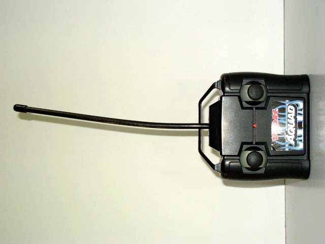
AEKA56349
Dec 06, 200649MHz TRANSMITTER
Equipment Class
DXX - Part 15 Low Power Communication Device Transmitter