AEKA14349RRemote Control Receiver
Taiyo Co., Ltd.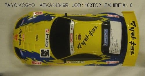
Click to zoom
Application Details
- Equipment Class
- CRR - Superregenerative Receiver
- Date of Grant
- Mar 07, 2002
- Application Purpose
- Original Equipment
- Date of Application
- Mar 07, 2002
- Equipment Note
- Remote Control Receiver
- Frequency Range
- 49.82000000 - 49.90000000
- Company
- Taiyo Co., Ltd.
- Country
- Japan
Documents & Files
Document Text
Text extracted from the exhibit documents filed with the FCC. Open a document above to read the original.
Operational Description
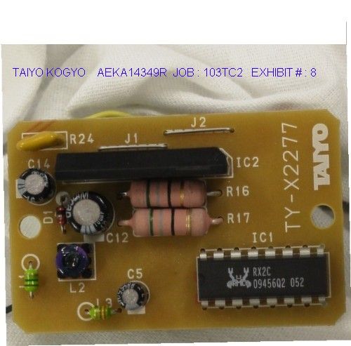
Circuit Description for Taiyo AEKA10349R This is a super-regenative receiver consisting of Q1 and its tuned circuit L2 and C2. IC1 is a decoder integrated circuit that generates the signals to drive the motors. The energy source is a 7.2 V battery that is regulated down to 3.3 Volts by Q2 and zener diode D1. Antenna and Ground. The antenna consists of a 6 inch wire inside the toy. There is no external ground connection. The printed circuit board pathways are the only ground connections. TAIYO KOGYO CO., LTD. FCC ID: AEKA14349R EXHIBIT #: 10
Test Report
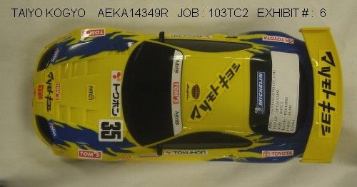
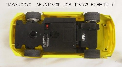
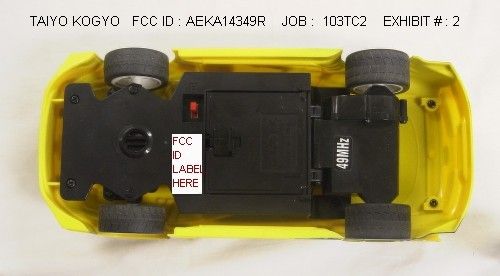
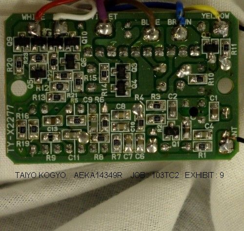
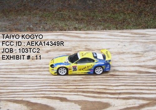
TABLE OF CONTENTS LIST APPLICANT: TAIYO KOGYO CO., LTD. FCC ID: AEKA14349R TEST REPORT CONTAINING: PAGE 1......TEST EQUIPMENT LIST PAGE 2......TEST PROCEDURES PAGE 3......RADIATION INTERFERENCE TEST DATA EXHIBITS CONTAINING: EXHIBIT 1............FCC ID LABEL SAMPLE EXHIBIT 2............SKETCH OF LABEL LOCATION EXHIBIT 3............BLOCK DIAGRAM EXHIBIT 4............SCHEMATIC EXHIBIT 5............USERS MANUAL EXHIBIT 6............EXTERNAL PHOTO - TOP VIEW EXHIBIT 7............EXTERNAL PHOTO – BOTTOM VIEW EXHIBIT 8............INTERNAL PHOTO - COMPONENT VIEW EXHIBIT 9............INTERNAL PHOTO - COPPER VIEW EXHIBIT 10...........CIRCUIT DESCRIPTION EXHIBIT 11...........TEST SET UP PHOTO APPLICANT: TAIYO KOGYO CO., LTD. FCC ID: AEKA14349R REPORT #: T\TAIYO\103TC2\103TC2RPT.doc PAGE: TABLE OF CONTENTS LIST APPLICANT: TAIYO KOGYO CO., LTD. FCC ID: AEKA14349R TEST EQUIPMENT LIST 1._X_Spectrum Analyzer: HP 8566B-Opt 462, S/N 3138A07786, w/ preselector HP 85685A, S/N 3221A01400, Quasi-Peak Adapter HP 8565OA, S/N 3303A01690 & Preamplifier HP 8449B-OPT H02, S/N 3008A00372 Cal. 8/31/01 Due 8/31/02 2._X_Biconnical Antenna: Eaton Model 94455-1, S/N 1057, Cal. 10/1/01 Due 10/1/02 3.__ Biconnical Antenna: Electro-Metrics Model BIA-25, S/N 1171 Cal. 4/26/01 Due 4/26/03 4._X_ Log-Periodic Antenna: Electro-Metrics Model EM-6950, S/N 632 Char. 10/15/01 Due 10/15/02 5.__ Log-Periodic Antenna: Electro-Metrics Model LPA-30, S/N 409 Char. 10/16/01 Due 10/16/02 6.__ Log-Periodic Antenna: Electro-Metrics Model LPA-25, S/N 1122 Char. 2/10/01 Due 3/10/02 7.__ Double-Ridged Horn Antenna: Electro-Metrics Model RGA-180, 1-18 GHz, S/N 2319 Cal. 12/19/01 Due 12/19/02 8.__ 18-26.3GHz Systron Donner Standard Gain Horn #DBE-520-20 No Cal Required 9.__ Horn 40-60GHz: ATM Part #19-443-6R No Cal Required 10.__ Line Impedance Stabilization Network: Electro-Metrics Model EM-7820, w/NEMA Adapter S/N 2682 Cal. 3/16/01 Due 3/16/02 11.__ Temperature Chamber: Tenney Engineering Model TTRC, S/N 11717-7 Char. 1/22/02 Due 1/22/03 12.__ Frequency Counter: HP Model 5385A, S/N 3242A07460 Char. 12/11/01 Due 12/11/02 13.__ Peak Power Meter: HP Model 8900C, S/N 2131A00545 Char. 1/26/01 Due 1/26/02 14._X_Open Area Test Site #1-3meters Cal. 12/22/99 15.__ Signal Generator: HP 8640B, S/N 2308A21464 Cal. 11/15/01 Due 11/15/02 16.__ Passive Loop Antenna: EMCO Model 6512, 9KHz to 30MHz, S/N 9706-1211 Char. 7/10/01 Due 7/10/02 17.__ Dipole Antenna Kit: Electro-Metrics Model TDA-30/1-4, S/N 152 Cal. 3/21/01 Due 3/21/02 18.__ AC Voltmeter: HP Model 400FL, S/N 2213A14499 Cal. 10/9/01 Due 10/09/02 19._X_Digital Multimeter: Fluke Model 77, S/N 35053830 Char. 1/8/02 Due 1/8/03 20.__ Oscilloscope: Tektronix Model 2230, S/N 300572 Char. 2/1/01 Due 2/1/02 APPLICANT: TAIYO KOGYO CO., LTD. FCC ID: AEKA14349R REPORT #: T\TAIYO\103TC2\103TC2RPT.doc PAGE: 1 TEST PROCEDURE GENERAL: This report shall NOT be reproduced except in full without the written approval of TIMCO ENGINEERING, INC. RADIATION INTERFERENCE: The test procedure used was ANSI STANDARD C63.4-1992 using a HEWLETT PACKARD spectrum analyzer with a prese- lector. The bandwidth of the spectrum analyzer was 100 kHz with an appropriate sweep speed. The analyzer was calibrated in dB above a microvolt at the output of the antenna. The resolution bandwidth was 100 kHz and the video bandwidth was 300 kHz. The ambient temperature of the UUT was 61ºF with a humidity of 76%. FORMULA OF CONVERSION FACTORS: The Field Strength at 3m was estab- lished by adding the meter reading of the spectrum analyzer (which is set to read in units of dBuV) to the antenna correction factor sup- plied by the antenna manufacturer. The antenna correction factors are stated in terms of dB. The gain of the Preselector was accounted for in the Spectrum Analyzer Meter Reading. Example: Freq (MHz) METER READING + ACF = FS 33 20 dBuV + 10.36 dB = 30.36 dBuV/m @ 3m ANSI STANDARD C63.4-1992 10.1.7 MEASUREMENT PROCEDURES: The unit under test was placed on a table 80 cm high and with dimensions of 1m by 1.5m. The table used for radiated measurements is capable of continu- ous rotation. When an emission was found, the table was rotated to produce the maximum signal strength. At this point, the antenna was raised and lowered from 1m to 4m. The antenna was placed in both the horizontal and vertical planes. The receiver was cohered with a signal generator. ANSI STANDARD C63.4-1992 12.1.1.1 For a superregenerative receiver: A Signal Generator was set to the unit under test operating frequency. An un-modulated continuous wave (CW) signal was radiated at the superregenerative receiver operating frequency to cohere the characteristic broadband emissions from the receiver. APPLICANT: TAIYO KOGYO CO., LTD. FCC ID: AEKA14349R REPORT #: T\TAIYO\103TC2\103TC2RPT.doc PAGE #: 2 APPLICANT: TAIYO KOGYO CO., LTD. FCC ID: AEKA14349R NAME OF TEST: RADIATION INTERFERENCE RULES PART NUMBER: 15.109 REQUIREMENTS: 30 to 88 MHz: 40.0 dBuV/M @ 3 METERS 88 to 216 MHz: 43.5 dBuV/M 216 to 960 MHz: 46.0 dBuV/M ABOVE 960 MHz: 54.0 dBuV/M TEST RESULTS: A search was made of the spectrum from 30 to 1000 MHz and the measurements indicate that the unit DOES meet the FCC requirements. TEST DATA: NO SIGNIFICANT EMISSIONS NOTED SAMPLE CALCULATION: FSdBuV/m = MR(dBuV) + ACFdB. TEST PROCEDURE: ANSI STANDARD C63.4-1992 using a Hewlett Packard Model 8566B spectrum analyzer, a Hewlett Packard Model 85685A Preselector, a Hewlett Packard Model 85650A Quasi-Peak adapter, and an appropriate antenna – see the test equipment list. The bandwidth of spectrum analyzer was 100 kHz with an appropriate sweep speed. When an emission was found, the table was rotated to produce the maximum signal strength. The antenna was placed in both the horizontal and vertical planes and the worse case emissions were reported. PERFORMED BY: JOSEPH SCOGLIO DATE:FEBRUARY 7, 2002 APPLICANT: TAIYO KOGYO CO., LTD. FCC ID: AEKA14349R REPORT #: T\TAIYO\103TC2\103TC2RPT.doc PAGE #: 3
Contact Information
Applicant
Hiroyuki Sasaki(Manager of Quality Assurance Section)
Test Firm
Timco Engineering, Inc.S Sanders
Technical Specifications
| # | Rule Parts | Frequency Range | Power Output |
|---|---|---|---|
| 1 | 15B | 49.82 MHz - 49.9 MHz | - |
Other Applications from Taiyo Co., Ltd.
AEKA54095
Oct 14, 2007REMOTE CONTROL TRANSMITTER
Equipment Class
TNB - Licensed Non-Broadcast Station Transmitter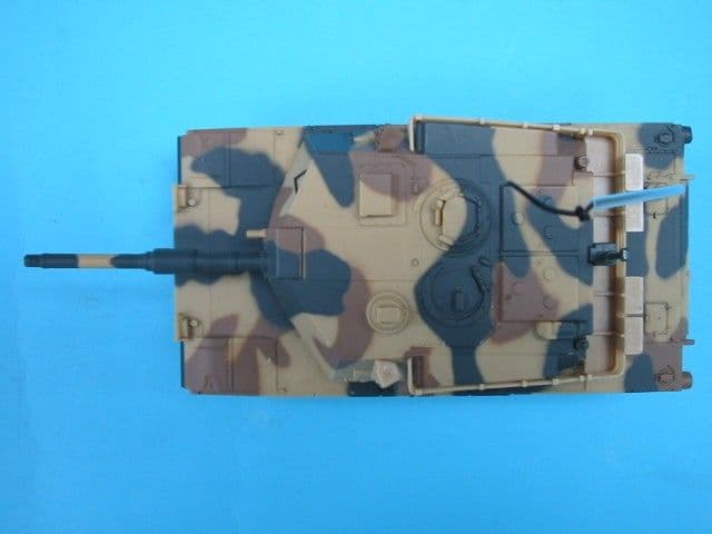
AEKA73049R
Sep 04, 2007BATTLE TANK
Equipment Class
CRR - Superregenerative Receiver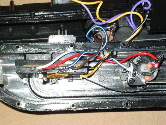
AEKA56349R
Dec 10, 200649MHz RECEIVER
Equipment Class
CRR - Superregenerative Receiver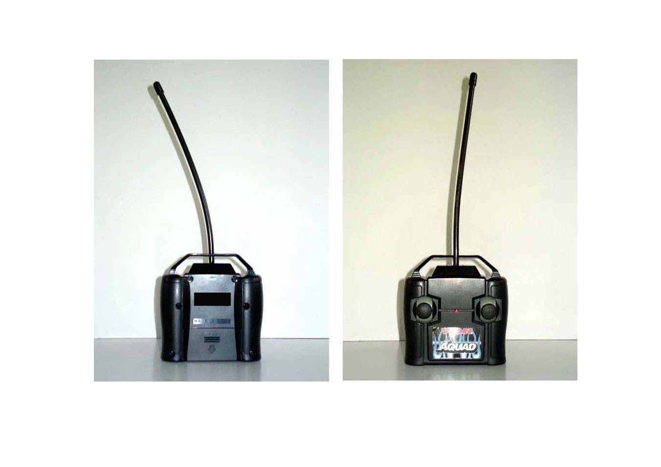
AEKA56327
Dec 06, 200627 MHz TRANSMITTER
Equipment Class
DXX - Part 15 Low Power Communication Device Transmitter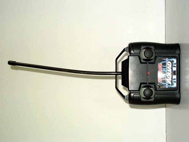
AEKA56349
Dec 06, 200649MHz TRANSMITTER
Equipment Class
DXX - Part 15 Low Power Communication Device Transmitter