AEKA3082727 MHz Remote Control Transmitter
Taiyo Co., Ltd.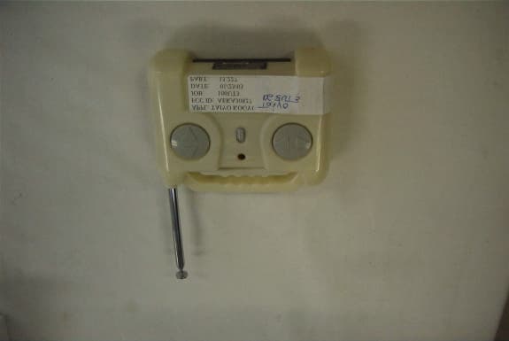
Click to zoom
Application Details
- Equipment Class
- DXX - Part 15 Low Power Communication Device Transmitter
- Date of Grant
- Apr 02, 2003
- Application Purpose
- Original Equipment
- Date of Application
- Apr 02, 2003
- Equipment Note
- 27 MHz Remote Control Transmitter
- Frequency Range
- 26.96000000 - 27.28000000
- Company
- Taiyo Co., Ltd.
- Country
- Japan
Documents & Files
Document Text
Text extracted from the exhibit documents filed with the FCC. Open a document above to read the original.
Users Manual
Keep these instructions for future reference: they contain important information. Guardar estas instrucciones para futura referencia, ya que contienen información de importancia acerca de este producto. LEA LAS INSTRUCCIONES ANTES DE USAR ESTE PRODUCTO. Conserver ces instructions pour s'y référer en cas de besoin; elle contiennent des renseignements importants. B7473-0720 U.S.A. 90-DAY LIMITED WARRANTY – TYCO® R/C PRODUCTS Mattel, Inc. warrants to the original consumer purchaser that this product will be free of defects in material and workmanship for ninety (90) days (unless specified in alternate warranties) from the date of purchase. Mattel will replace the product in the event of such a defect within the warranty period. In the event of a defect covered under this warranty, first call the toll-free number listed below. Many problems can be solved in this manner. If necessary, you will be instructed to return the product, postage prepaid and insured, to the address below. Enclose your name, address, dated sales receipt, and a brief explanation of the defect. Replacement and return shipment will be free of charge. This warranty does not cover damage resulting from unauthorized modification, accident, misuse or abuse. If the product is returned without a dated sales receipt the product may be excluded from coverage under this warranty. Mattel’s liability for defects in material and workmanship under this warranty shall be limited to replacement, and in no event shall we be responsible for incidental, consequential, or con- tingent damages (except in those states that do not allow this exclusion or limitation). This warranty is exclusive, and is made in lieu of any express or implied warranty. Valid only in U.S.A. This warranty gives you specific legal rights and you may have other rights, which vary from state to state. Some states do not allow the exclusion of incidental or consequential damages, so the above exclusions or limitations may not apply to you. TOLL-FREE NUMBER: 1-888-557-TYCO (8926) (valid only in U.S.A.) Hours: 8:00 A.M. - 5:00 P.M. Eastern Time; Monday - Friday. Expect some delay in January following the holiday season. Please be patient and keep trying the toll-free number. ADDRESS FOR RETURNS: CONSUMER RELATIONS, 636 GIRARD AVENUE, EAST AURORA, NY 14052 CANADA 90-DAY LIMITED WARRANTY Mattel, Inc. warrants to the original consumer purchaser that this product will be free of defects in material and workmanship for ninety (90) days (unless specified in alternate warranties) from the date of purchase. If defective, return the product along with proof of the date of purchase, postage prepaid to Mattel Canada Inc., Consumer Service, 6155 Freemont Blvd., Mississauga, Ontario L5R 3W2 for replacement with an identical toy or a similar toy of equal or greater value according to availability. This warranty gives you specific legal rights and you may have other rights which vary from province to province. This warranty does not cover damage resulting from accident, misuse or abuse. Valid for products sold in Canada only. YOU MAY CALL US FREE AT 1-800-665-6288 Monday – Friday, 8:00 a.m. – 5:00 p.m. EST; 5:00 a.m. – 2:00 p.m. PST. CANADA GARANTIE LIMITÉE DE 90 JOURS Mattel garantit à l’acheteur initial que le produit est couvert contre les vices de matériau ou de fabrication pour une période de 90 jours (à moins d’indication contraire dans d’autres garanties) à compter de la date d’achat. Tout produit défectueux doit être retourné, accompagné d’une preuve de la date d’achat et dûment affranchi, au Service à la clientèle de Mattel Canada Inc., 6155, Freemont Blvd., Mississauga (Ontario) L5R 3W2, où il sera remplacé par un produit identique ou un produit semblable de valeur égale ou supérieure, selon la disponibilité. La présente garantie procure certains droits légaux à l’acheteur, qui peut également bénéficier de droits supplémentaires qui varient d’une province à l’autre. La présente garantie ne couvre pas les dommages occasion- nés par un accident ou un usage abusif ou inapproprié. Valable pour les pro- duits vendus au Canada seulement. QUESTIONS OU COMMENTAIRES? COMPOSEZ SANS FRAIS LE 1 800 665- MATTEL (1 800 665-6288) du lundi au vendredi, de 8 h à 17 h (HNE) ou de 5 h à 14 h (HNP). Mattel de México, S.A. De C.V., garantiza sus productos por un periodo de 90 días en todas sus partes y mano de obra, a partir de la fecha de entrega. Condiciones: 1.- El consumidor presentará el producto en el lugar donde lo adquirió y/o presentarlo o enviarlo a nuestro centro de servicio ubicado en Lebrija 296-a, Col. Cerro de la Estrella, Iztapalapa C.P. 09880, México, D.F. Tels: 426-44-87 y 426-44-38 2.- Durante la vigencia de esta póliza nos compromete- mos a efectuar sin cargo la reparación, en un plazo que no excederá de 30 días a partir de la fecha de recepción del producto en nuestro sentro de servicio, o al cambio del producto defectuoso en su caso. Así mismo cubrimos gastos que se deriven de la presenta garantía. 3.- Refacciones para este producto podrán ser adquiridas en nuestro centro de servicio. Esta garantía se invalida en los sigu- ientes casos: si ha sufrido un deterioro esencial, grave o irreparable por causa del consumidor, por daños causados por maltrato, mal uso, golpes accidentales o intencionales, o que el artículo se hay expuesto a elementos como agua (a excepción de que el instructivo indique otra cosa), ácidos, fuego, intemperie, así como daños causados por baterías que se dejen dentro del juguete por largos periodos de tiempo sin uso. NOMBRE DEL CONSUMIDOR: LÍNEA DE PRODUCTO: _____________________________________________ SERIE: __________________________________________________________ MODELO: _______________________________________________________ NOMBRE DEL DISTRIBUIDOR: _______________________________________ DIRECCIÓN: _____________________________________________________ SELLO O FIRMA DEL DISTRIBUIDOR: _________________________________ FECHA DE COMPRA: _______________…
Text truncated - open the document above for the full version.
Users Manual
❺ ❹ ❷ ❶ ❹ ❶ ❷ ❸ ❹ ❺ ① ② ❸ ③ ④ ⑤ ❶ ❷ 9V d.c. 8 x 1.5V d.c. 1x = 25% 2x = 75% 3x = 100% ❶ ❷ 150’/50m ❷ ❶ ❷ ❸ ❹ ❺ ❹ ❽ 3x = 100%
Users Manual
I. CONTENTS/FEATURES (Batteries not included) ① SKY SCORCHER™ plane (Bottom View) ❶ Power connector door ❷Power connector (plugs into charger) ❸ON/OFF switch ❹Propellers (2) ❺Wire antenna ② Transmitter ❶Throttle control ❷Steering control ❸ON/OFF switch ❹Screw-in telescoping antenna ❺Antenna ribbon • Before operating your plane for the first time, carefully screw the antenna into the transmitter. Make sure the antenna is fully extended before operating. • Hook the end of the ribbon onto the antenna as shown. ❸ Charger (recharges plane) CAUTION:Use only the charger supplied with this toy. Do not use any other charging source. II. BATTERY INSTALLATION Charger • Unscrew battery door (screwdriver not included). • Install 8 C-type alkaline batteries, with polarity (+/-) as shown, inside battery compartment. • Close battery door and tighten screws. Transmitter • To install transmitter battery, open bat- tery cover as shown. • Install one 9V battery with polarity (+/-) as shown inside battery compartment. • Replace battery cover. III. CHARGING THE PLANE Your plane is powered by a NiMH battery that is permanently installed. The plane must be charged before using. To charge, first make sure you have installed 8 C-type alkaline batteries in the charger as shown in Section II. Then follow these easy steps: ❶Make sure the plane’s power switch is in the OFF position. ❷Press down on the power connector door and slide it backward. Swing the power connector door open to access the plane’s wire connec- tor. ❸Set the plane on top of the charger. Plug the plane’s wire connector into the charger as shown. Make sure the connection is secure. ❹Press and release the CHARGE button. ❺The red LED charge indicator will begin flash- ing, showing that the battery is being charged. ❻ The charging process takes just a few min- utes. When the charge indicator goes off, the charging cycle is complete. ❼ Disconnect the plane’s wire connector. ❽ Replace the wire connector inside its com- partment and close the plane’s power connec- tor door. Do not attempt to recharge the plane until it’s fully discharged (after your flight). Additional charging will not increase running time, and may damage the plane’s permanent battery. Always hold the wire connectors when disconnecting. NEVER pull the wires to disconnect; this may cause the wires to break. IV. THROTTLE CONTROLS The transmitter’s left control operates the power of the plane’s engines. ❶There are three power levels: 1. Low power (approximately 25% engine power). Use low power for decelerating and descending. 2. Medium power (approximately 75% engine power). Use medium power for cruising and normal maneuvers. 3. Full power (100% engine power). Use full power for take-offs and climbing. ❷Press the control up to increase power level: 1. Press once for low power. Release the control to remain at low power. 2. Press twice for medium power. Release the control to remain at medium power. 3. When engines are at medium power, pressing and holding the forward button will activate full power. When you release the control, the engines will return to medium power. ❸Press the throttle control down to decrease power level: 1. From medium power level: press once to reduce to low power. Release the control to remain at low power. 2. From low power level: press once to shut off the engines (for landing or to conserve battery power). V. STEERING CONTROLS The transmitter’s right control operates steering. Press left to steer left. Press right to steer right. The steering controls are extremely sensitive. Don’t over- steer! For best results, steer by gently tapping the control left or right. VI. PRE-FLIGHT CHECK ❶Choose the Right Location. Give yourself plenty of flying room. For best results, you should have at least 150’/50m of open space in all directions. Avoid tall buildings, trees and power lines. They may obstruct your flight path, and they may create air currents that make it difficult to operate your plane. DO NOTfly in the street! ❷Check the Conditions. Like all planes, your plane is very sensitive to air conditions. The antenna ribbon is provided to help you gauge the air condi- tions. When the ribbon is in the “YES” zone , the air currents are OK for flying. When the ribbon is in the “NO” zone , the air currents are too strong for flying. DO NOTattempt to operate your plane in strong winds. Strong winds will make it difficult to fly safely, and will reduce bat- tery life and flying time. Remember that the wind may be stronger at higher alti- tudes than at ground level. ❸Be Careful! Be a safe pilot...use common sense and care when flying. Watch out for people, animals and obstacles. VII. READY TO FLY! Your plane is easy to fly, but you’ll need to put in some flight time to become an ace pilot. Practice these steps to sharpen your skills. ❶Charge the plane (see Section III). Turn the plane ON. Turn the transmitter ON. When you turn the plane ON, the propellers will spin quickly for a moment, and then stop. Keep clear of the propellers! ❷Make sure the plane’s wire antenna is straight and dangling behind the tail wing. Check the direction of the breeze, and make sure you are facing into the breeze when you launch the plane (please see illustration). ❸ Set the engines to full power (press throttle control up two times, then press and hold). ❹Hold the airplane just underneath the wings. Still holding the throttle control at full power, launch the plane horizon- tally into the breeze. You may want to launch the plane while running, or you may want to ask a friend to launch the plane while you operate the controls. ❺Hold the throttle control at full power until the plane has climbed to approxi- mately 30’/9m. Then release the throttle control to reduce power level to medi- um...for normal cruising and maneu- vers. With practice, you may want to try releasing the throttle control at higher or lower altitudes. For the first few flights, you may want to keep the throttle at full power for th…
Text truncated - open the document above for the full version.
Operational Description
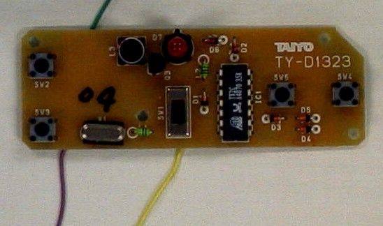
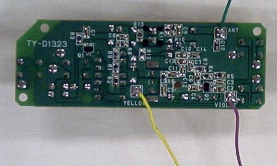
TAIYO KOGYO CO., LTD. – FCC Id: AEKA30827 OPERATIONAL DESCRIPTION X1 is the crystal controller oscillator. Q2 is the RF amplifier. IC1 is the modulation source which is applied to the base of Q2. The antenna coupling and harmonic suppression components are O6, C7, L3, C8, and L4. Power is supplied via a 9V primary cell battery and regulated down to 5.1 Volts by diode D6. This device has no external ground connection and the printed circuit board traces are the only ground connection. The antenna is a permanently attached 9 inch long piece of wire.
Test Report
TIMCO ENGINEERING INC. 849 NW State Road 45 Newberry, Florida 32669 http://www.timcoengr.com 888.472.2424 F 352.472.2030 email: [email protected] APPLICANT: TAIYO KOGYO CO., LTD. FCC ID: AEKA30827 REPORT #: T\Taiyo_AEK\106YUT3\106YUT3TestReport.doc COVER SHEET Test Report Product Name: 27 MHz REMOTE CONTROL TRANSMITTER - REPAIR & RETEST FCC ID: AEKA30827 Applicant: TAIYO KOGYO CO., LTD. NO 1-23-17, HIGASHIYOTSUGI KATSUSHIKA-KU TOKYO 124 JAPAN Date Receipt: FEBRUARY 12, 2003 Date Tested: FEBRUARY 14, 2003 TIMCO ENGINEERING INC. 849 NW State Road 45 Newberry, Florida 32669 http://www.timcoengr.com 888.472.2424 F 352.472.2030 email: [email protected] APPLICANT: TAIYO KOGYO CO., LTD. FCC ID: AEKA30827 REPORT #: T\Taiyo_AEK\106YUT3\106YUT3TestReport.doc TABLE OF CONTENTS TABLE OF CONTENTS LIST APPLICANT: TAIYO KOGYO CO., LTD. FCC ID: AEKA30827 TEST REPORT CONTAINING: PAGE 1-3.............TEST EQUIPMENT LIST PAGE 4...............TEST PROCEDURE PAGE 5...............RADIATION INTERFERENCE TEST DATA PAGE 6...............OCCUPIED BANDWIDTH PAGE 7...............OCCUPIED BANDWIDTH PLOT EXHIBITS CONTAINING: EXHIBIT 1............BLOCK DIAGRAM EXHIBIT 2............SCHEMATIC EXHIBIT 3............INSTRUCTION MANUAL EXHIBIT 4............SAMPLE OF FCC ID LABEL EXHIBIT 5............LOCATION OF FCC ID LABEL EXHIBIT 6............EXTERNAL PHOTOGRAPHS EXHIBIT 7............INTERNAL PHOTOGRAPHS EXHIBIT 8............CIRCUIT DESCRIPTION EXHIBIT 9............TEST SET UP PHOTOGRAPH TIMCO ENGINEERING INC. 849 NW State Road 45 Newberry, Florida 32669 http://www.timcoengr.com 888.472.2424 F 352.472.2030 email: [email protected] APPLICANT: TAIYO KOGYO CO., LTD. FCC ID: AEKA30827 REPORT #: T\Taiyo_AEK\106YUT3\106YUT3TestReport.doc Page 1 of 7 EMC Equipment List DEVICE MFGR MODEL SERNO CAL/CHAR DATE DUE DATE or STATUS X 3-Meter OATS TEI N/A N/A Listed 12/22/99 12/22/02 3/10-Meter OATS TEI N/A N/A Listed 3/26/01 3/26/04 Receiver, Beige Tower Spectrum Analyzer (Tan) HP 8566B Opt 462 3138A07786 3144A20661 CAL 8/31/01 8/31/03 RF Preselector (Tan) HP 85685A 3221A01400 CAL 8/31/01 8/31/03 Quasi-Peak Adapter (Tan) HP 85650A 3303A01690 CAL 8/31/01 8/31/03 X Receiver, Blue Tower X Spectrum Analyzer (Blue) HP 8568B 2928A04729 2848A18049 CHAR 10/22/01 10/22/03 X RF Preselector (Blue) HP 85685A 2926A00983 CHAR 10/22/01 10/22/03 X Quasi-Peak Adapter (Blue) HP 85650A 2811A01279 CHAR 10/22/01 10/22/03 X Biconnical Antenna Electro-Metrics BIA-25 1171 CAL 4/26/01 4/26/03 Biconnical Antenna Eaton 94455-1 1096 CAL 10/1/01 10/1/03 Biconnical Antenna Eaton 94455-1 1057 CHAR 3/15/00 3/15/02 BiconiLog Antenna EMCO 3143 9409-1043 X Log-Periodic Antenna Electro-Metrics LPA-25 1122 CAL 10/2/01 10/2/03 Log-Periodic Antenna Electro-Metrics EM-6950 632 CHAR 10/15/01 10/15/03 Log-Periodic Antenna Electro-Metrics LPA-30 409 CHAR 10/16/01 10/16/03 Dipole Antenna Kit Electro-Metrics TDA-30/1-4 152 CAL 3/21/01 3/21/04 Dipole Antenna Kit Electro-Metrics TDA-30/1-4 153 CHAR 11/24/00 11/24/03 Double-Ridged Horn Antenna Electro-Metrics RGA-180 2319 CAL 12/19/01 12/19/03 Horn Antenna Electro-Metrics EM-6961 6246 CAL 3/21/01 3/21/03 TIMCO ENGINEERING INC. 849 NW State Road 45 Newberry, Florida 32669 http://www.timcoengr.com 888.472.2424 F 352.472.2030 email: [email protected] APPLICANT: TAIYO KOGYO CO., LTD. FCC ID: AEKA30827 REPORT #: T\Taiyo_AEK\106YUT3\106YUT3TestReport.doc Page 2 of 7 DEVICE MFGR MODEL SERNO CAL/CHAR DATE DUE DATE or STATUS Horn Antenna ATM 19-443-6R None No Cal Required Passive Loop Antenna EMC Test Systems EMCO 6512 9706-1211 CHAR 7/10/01 7/10/03 Line Impedance Stabilization . . . Electro-Metrics ANS-25/2 2604 CAL 10/9/01 10/9/03 Line Impedance Stabilization . . . Electro-Metrics EM-7820 2682 CAL 3/16/01 3/16/03 Termaline Wattmeter Bird Electronic Corporation 611 16405 CAL 5/25/99 5/25/01 Termaline Wattmeter Bird Electronic Corporation 6104 1926 CAL 12/12/01 12/12/03 Oscilloscope Tektronix 2230 300572 CHAR 2/1/01 2/1/03 Temperature Chamber Tenney Engineering TTRC 11717-7 CHAR 1/22/02 1/22/04 AC Voltmeter HP 400FL 2213A14499 CAL 10/9/01 10/9/03 AC Voltmeter HP 400FL 2213A14261 CHAR 10/15/01 10/15/03 AC Voltmeter HP 400FL 2213A14728 CHAR 10/15/01 10/15/03 X Digital Multimeter Fluke 77 35053830 CHAR 1/8/02 1/8/04 Digital Multimeter Fluke 77 43850817 CHAR 1/8/02 1/8/04 Digital Multimeter HP E2377A 2927J05849 CHAR 1/8/02 1/8/04 Multimeter Fluke FLUKE-77-3 79510405 CAL 9/26/01 9/26/03 Peak Power Meter HP 8900C 2131A00545 CHAR 1/26/01 1/26/03 Digital Thermometer Fluke 2166A 42032 CAL 1/16/02 1/16/04 Thermometer Traulsen SK-128 CHAR 1/22/02 1/22/04 X Temp/Humidity gauge EXTech 44577F E000901 CHAR 1/22/02 1/22/04 Frequency Counter HP 5352B 2632A00165 CAL 11/28/01 11/28/03 Power Sensor Agilent Technologies 84811A 2551A02705 CAL 1/26/01 1/26/03 TIMCO ENGINEERING INC. 849 NW State Road 45 Newberry, Florida 32669 http://www.timcoengr.com 888.472.2424 F 352.472.2030 email: [email protected] APPLICANT: TAIYO KOGYO CO., LTD. FCC ID: AEKA30827 REPORT #: T\Taiyo_AEK\106YUT3\106YUT3TestReport.doc Page 3 of 7 DEVICE MFGR MODEL SERNO CAL/CHAR DATE DUE DATE or STATUS Service Monitor IFR FM/AM 500A 5182 CAL 11/22/00 11/22/02 Comm. Serv. Monitor IFR FM/AM 1200S 6593 CAL 5/12/02 5/12/04 Signal Generator HP 8640B 2308A21464 CAL 11/15/01 11/15/03 Modulation Analyzer HP 8901A 3435A06868 CAL 9/5/01 9/5/03 Near Field Probe HP HP11940A 2650A02748 CHAR 2/1/01 2/1/03 BandReject Filter Lorch Microwave 5BR4-2400/ 60-N Z1 CHAR 3/2/01 3/2/03 BandReject Filter Lorch Microwave 6BR6-2442/ 300-N Z1 CHAR 3/2/01 3/2/03 BandReject Filter Lorch Microwave 5BR4-10525/ 900-S Z1 CHAR 3/2/01 3/2/03 High Pas Filter Microlab HA-10N CHAR 10/4/01 10/4/03 Audio Oscillator HP 653A 832-00260 CHAR 3/1/01 3/1/03 Frequency Counter HP 5382A 1620A03535 CHAR 3/2/01 3/2/03 Frequency Counter HP 5385A 3242A07460 CHAR 12/11/01 12/11/03 Preamplifier HP 8449B-H02 3008A00372 CHAR 3/4/01 3/4/03 Amplifier HP 11975A 2738A01969 CHAR 3/1/01 3/1/03 Egg Timer Unk CHAR 8/31/01 8/31/03 Measuring Tape, 20M Kraftixx 06…
Text truncated - open the document above for the full version.
Contact Information
Applicant
Hiroyuki Sasaki(Manager of Quality Assurance Section)
Test Firm
Timco Engineering, Inc.S Sanders
Technical Specifications
| # | Rule Parts | Frequency Range | Power Output |
|---|---|---|---|
| 1 | 15C | 26.96 MHz - 27.28 MHz | - |
Other Applications from Taiyo Co., Ltd.
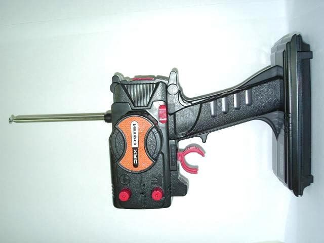
AEKA54095
Oct 14, 2007REMOTE CONTROL TRANSMITTER
Equipment Class
TNB - Licensed Non-Broadcast Station Transmitter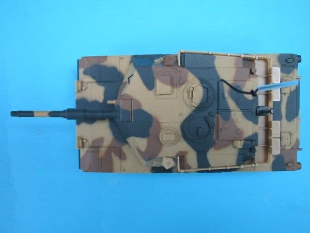
AEKA73049R
Sep 04, 2007BATTLE TANK
Equipment Class
CRR - Superregenerative Receiver
AEKA56349R
Dec 10, 200649MHz RECEIVER
Equipment Class
CRR - Superregenerative Receiver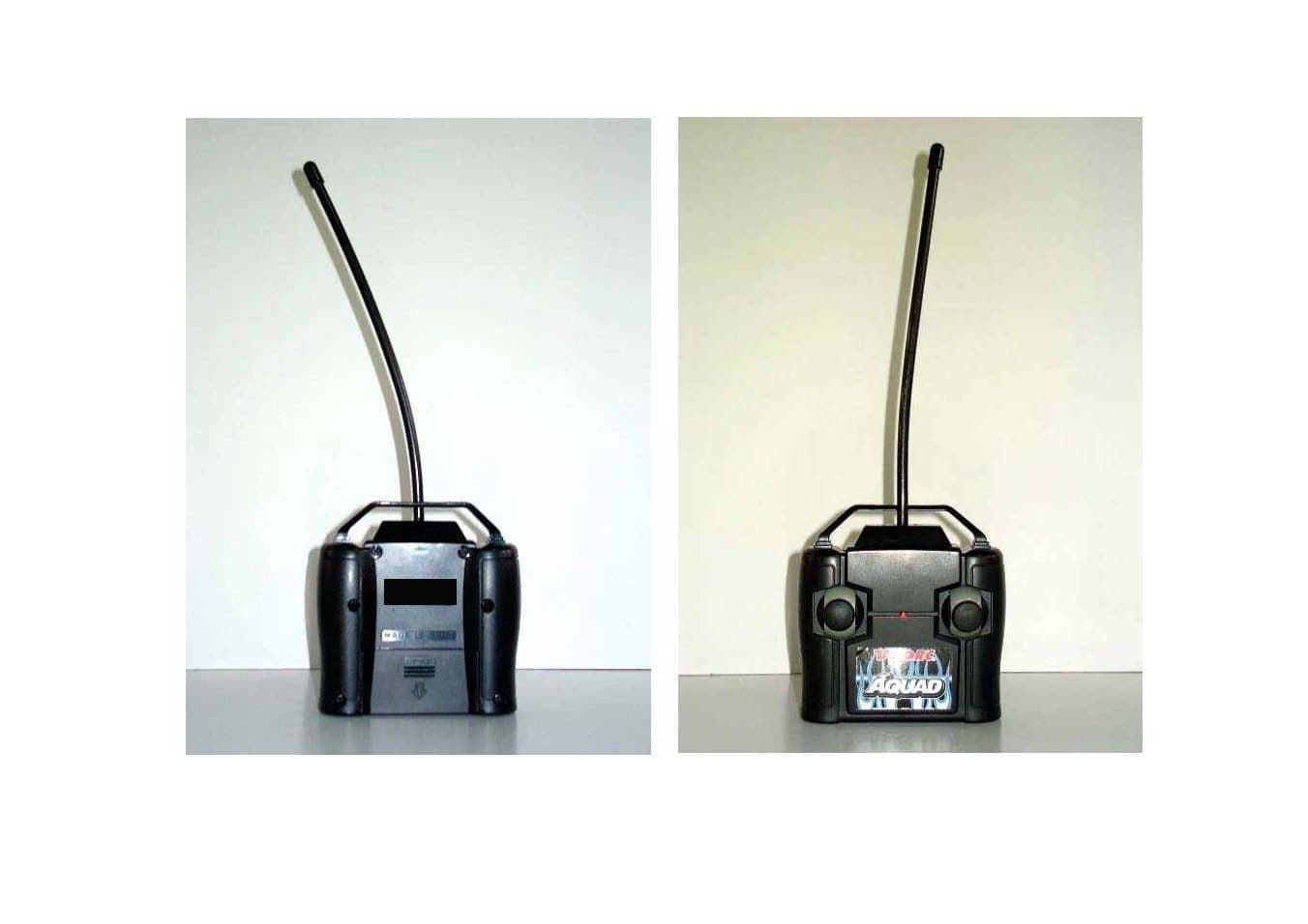
AEKA56327
Dec 06, 200627 MHz TRANSMITTER
Equipment Class
DXX - Part 15 Low Power Communication Device Transmitter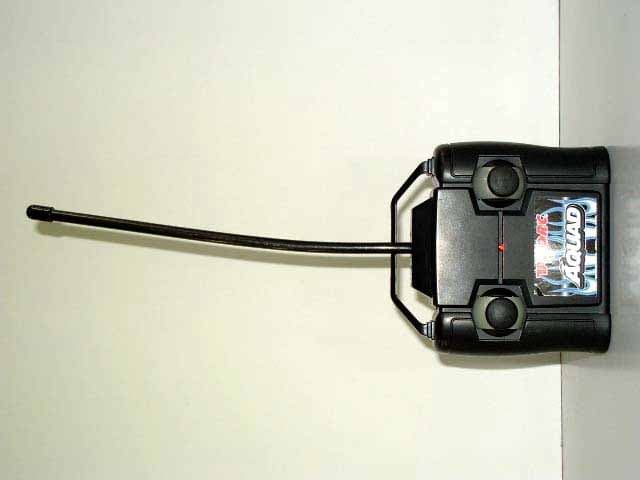
AEKA56349
Dec 06, 200649MHz TRANSMITTER
Equipment Class
DXX - Part 15 Low Power Communication Device Transmitter