AEKA32349RREMOTE CONTROL RECEIVER
Taiyo Co., Ltd.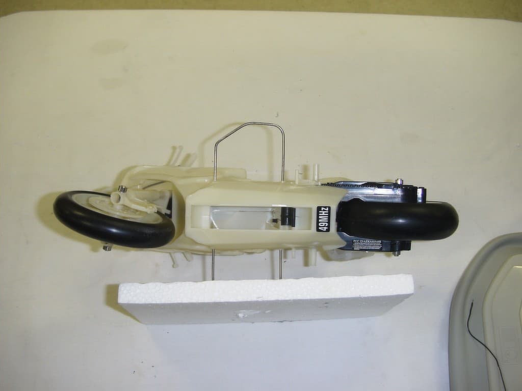
Click to zoom
Application Details
- Equipment Class
- CRR - Superregenerative Receiver
- Date of Grant
- Feb 09, 2004
- Application Purpose
- Original Equipment
- Date of Application
- Feb 09, 2004
- Equipment Note
- REMOTE CONTROL RECEIVER
- Frequency Range
- 49.82000000 - 49.90000000
- Company
- Taiyo Co., Ltd.
- Country
- Japan
Documents & Files
Document Text
Text extracted from the exhibit documents filed with the FCC. Open a document above to read the original.
Users Manual
O WN E R ’ S MA N U A L Thank you for your purchase of TAIYO product. Important! Please read your Owner's Manual all the way through before operating your vehicle. Contains important information---keep for future reference. B AT T E RY C H A R G I N G /C A R E -Misuse of the batteries can pose such risk as heat generation, explosion and leakage. -Only batteries of the same or equivalent type as recommended are to be used. -Batteries are to be inserted with the correct polarity. -The supply terminals are not to be short-circuited. -Exhausted batteries are to be removed from the vehicle. -Never immerse the battery in water or put into open flame. Also never attempt to disassemble or solder the battery. -When the battery gets wet with water, stop using it immediately. -The vehicle will not operate without the 6.0V rechargeable NiCd battery pack and 6.0V charger. -This economical rechargeable system is the only battery pack and charger made to power the vehicle. -The battery charger provided is to be regularly examined for damage to enclosure and other parts. In the event of damage, the vehicle must not be used with the battery charger until the damage has been repaired. -Rechargeable batteries are only to be recharged under adult supervision. -Rechargeable batteries are to be removed from the vehicle before being charged. -Non-rechargeable batteries are not to be recharged. -Inferior quality battery packs will shorten running time and may void the warranty. -Rechargeable up to 1000 times! -The vehicle is not to be connected to more than the recommended number of supplies. -Plug wall pack charger into standard 230 volt outlet. -Click the battery pack into the charger. Make certain the battery pack is secure in charger. -To disconnect, push the red button on the side of charger and simultaneously slide battery pack out. -After charging for 4 hours, the battery will feel warm. This condition is normal for fully charged batteries. -New battery packs must be charged for 5 1/2 hours the first two times charged. Subsequent charges will only require 4 hours. -Unlike alkaline batteries, where the power loss is gradual, a NiCd (nickel-cadmium) battery will suddenly lose much of its power. When this happens it is time to recharge the battery pack. -After use, the battery pack will be hot! Wait at least 20 minutes until the battery pack cools before recharging. Recharging a warm or hot battery pack will greatly reduce the number of times your battery pack can be recharged. THIS PRODUCT USES A NICKEL CADMIUM BATTERY. MUST BE RECYCLED OR DISPOSED OF PROPERLY. Contact your local area office of solid waste management or other appropriate local agency for information. R E D L I GH T R E L E AS E B UT T ON S a f e t y F i r s t Adult supervision is recommended, when the vehicle is operated. -To avoid danger, never drive the vehicle on streets or in crowded place. When playing outdoors, choose the place to play safely. -When a thunder is heard while playing outdoors, immediately stop using the vehicle. Otherwise lightning strike may be induced. -Avoid rough handling such as letting the vehicle hit something or waving the vehicle in the air. -When running the vehicle indoors, take due care not to break glass or damage furniture. -Keep away your fingers, hair and loose clothing from the running tires while the product is switched "ON". -Avoid leaving the vehicle in a place with high temperature such as the vicinity of a stove. -Do not point the transmitter antenna to somebody's head or animals. Otherwise unexpected accident may result. -In order to race or operate two vehicles together, the vehicles should not be operated on the same frequency at the same time. -The transmitter allows easier transmission of radio wave when it is held at higher position. If vehicle goes out of range, try lifting transmitter high into air to increase range. -Radio interference can be caused by the operation of your vehicle near HIGH VOLTAGE ELECTRICAL WIRES, LARGE STEEL REINFORCED CON- CRETE BUILDINGS and PASSING TRUCKS WITH CB RADIOS. Avoid these if possible. -This product is equipped with numerous parts including precision electronic circuits. Never attempt to disassemble or modify the product. Ni-Cd A3231 6 2 . B a t t e r y I n s t a l l a t i o n •Transmitter Slide open the battery door on back of Transmitter, pull it toward the direction shown in the figure while pressing lightly on its center. Insert fresh/new 9V (6LR61) battery with the polarity ( / ) as shown inside battery compartment. 1 . C o n t e n t s Battery Release Button Side Stabilizer (One each side) Stand Rear Working Suspension ON/OFF Switch Front Working Suspension Left Stick(Controls forward,stop and braking) Power Indicator -Vehicle 1.Always use the fully charged 6.0V Ni-Cd battery pack. 2.As preparation, turn the battery compartment latch in the bottom of the chassis to the lateral position. 3.Confirm that the main switch is OFF. Then set the battery pack in the bottom of the chassis while orienting it as shown in the figure. Turn the battery latch 90 degrees to fix the battery pack. 4.To remove the battery pack, rotate the battery compartment latch. ESTIMATED RUN TIME FOR THIS VEHICLES: 20-30 MINUTES "Smart Circuitry" Your precision vehicle is equipped with advanced circuitry designed to protect electronic components under extreme operating conditions. If vehicle stops running during use, simply allow the joysticks to return to their neutral positions for 15 to 20 seconds, then resume normal operation. A3232 Poseable Rider Front Working Suspension Side Stabilizer (One each side) Rear Working Suspension Antenna Right Stick (Controls steering) Antenna Right Stick (Controls steering) Power Indicator Left Stick(Controls forward,stop and braking) 3 . B e f o r e O p e r a t i o n 1.Attach the rider figure's feet as shown. 2.Attach the rider figure's hands as shown. 3.You may want to slide the first hand onto the hand grip, and snap on the second hand. 4.Turn …
Text truncated - open the document above for the full version.
Operational Description
CIRCUIT DESCRIPTION FOR TAIYO AEKA32349R This is a super-regenerative receiver consisting of Q1 and its tuned circuit L2 and C2. IC1 is a decoder integrated circuit that generates the signals to drive the motors. The energy source is a 6.0V battery that is regulated down to 3.3 volts by Q2 and zener diode D1.
Test Report
TIMCO ENGINEERING INC. 849 NW State Road 45 Newberry, Florida 32669 http://www.timcoengr.com 888.472.2424 F 352.472.2030 email: [email protected] APPLICANT: TAIYO KOGYO CO., LTD. Test Report Product Name: REMOTE CONTROL RECEIVER FCC ID: AEKA32349R Applicant: TAIYO KOGYO CO., LTD. NO 1-23-17, HIGASHIYOTSUGI KATSUSHIKA-KU TOKYO 124 JAPAN Date Receipt: JANUARY 19, 2004 Date Tested: FEBRUARY 3, 2004 FCC ID: AEKA32349R REPORT #: T\TAIYO_AEK\55JT4\55JT4TestReport.doc COVER SHEET TIMCO ENGINEERING INC. 849 NW State Road 45 Newberry, Florida 32669 http://www.timcoengr.com 888.472.2424 F 352.472.2030 email: [email protected] APPLICANT: TAIYO KOGYO CO., LTD. TABLE OF CONTENTS LIST APPLICANT: TAIYO KOGYO CO., LTD. FCC ID: AEKA32349R TEST REPORT CONTAINING: PAGE 1...............TEST EQUIPMENT LIST PAGE 2...............TEST PROCEDURES PAGE 3...............RADIATION INTERFERENCE TEST DATA EXHIBITS CONTAINING: BLOCK DIAGRAM SCHEMATIC INSTRUCTION MANUAL LABEL SAMPLE LABEL LOCATION EXTERNAL PHOTOGRAPHS INTERNAL PHOTOGRAPHS CIRCUIT DESCRIPTION TEST SET UP PHOTOGRAPH FCC ID: AEKA32349R REPORT #: T\TAIYO_AEK\55JT4\55JT4TestReport.doc TABLE OF CONTENTS TIMCO ENGINEERING INC. 849 NW State Road 45 Newberry, Florida 32669 http://www.timcoengr.com 888.472.2424 F 352.472.2030 email: [email protected] APPLICANT: TAIYO KOGYO CO., LTD. EMC Equipment List Device Manufacturer Model Serial Number Cal/Char Date Due Date 3/10-Meter OATS TEI N/A N/A Listed 3/26/01 3/26/04 3-Meter OATS TEI N/A N/A Listed 1/13/03 1/13/06 Biconnical Antenna Eaton 94455-1 1057 CAL 3/18/03 3/18/05 Biconnical Antenna Eaton 94455-1 1096 CAL 10/1/01 10/1/03 Biconnical Antenna Electro- Metrics BIA-25 1171 CAL 4/26/01 4/26/03 Blue Tower Quasi-Peak Adapter HP 85650A 2811A01279 CAL 4/15/03 4/15/05 Blue Tower RF Preselector HP 85685A 2926A00983 CAL 4/15/03 4/15/05 Blue Tower Spectrum Analyzer HP 8568B 2928A04729 2848A18049 CAL 4/15/03 4/15/05 LISN Electro- Metrics ANS-25/2 2604 CAL 10/9/01 10/9/03 LISN Electro- Metrics EM-7820 2682 CAL 3/12/03 3/12/05 Log- Periodic Antenna Eaton 96005 1243 CAL 5/8/03 5/8/05 FCC ID: AEKA32349R REPORT #: T\TAIYO_AEK\55JT4\55JT4TestReport.doc Page 1 of 3 TIMCO ENGINEERING INC. 849 NW State Road 45 Newberry, Florida 32669 http://www.timcoengr.com 888.472.2424 F 352.472.2030 email: [email protected] APPLICANT: TAIYO KOGYO CO., LTD. TEST PROCEDURE GENERAL: This report shall NOT be reproduced except in full without the written approval of TIMCO ENGINEERING, INC. RADIATION INTERFERENCE: The test procedure used was ANSI STANDARD C63.4-2001 using a HEWLETT PACKARD spectrum analyzer with a pre-selector. The bandwidth of the spectrum analyzer was 100 kHz with an appropriate sweep speed. The analyzer was calibrated in dB above a microvolt at the output of the antenna. The resolution bandwidth was 100KHZ and the video bandwidth was 300KHZ. The ambient temperature of the UUT was 65ºF with a humidity of 70%. FORMULA OF CONVERSION FACTORS: The Field Strength at 3m was established by adding the meter reading of the spectrum analyzer (which is set to read in units of dBuV) to the antenna correction factor supplied by the antenna manufacturer. The antenna correction factors are stated in terms of dB. The gain of the Preselector was accounted for in the Spectrum Analyzer Meter Reading. Example: Freq (MHz) METER READING + ACF = FS 33 20 dBuV + 10.36 dB = 30.36 dBuV/m @ 3m ANSI STANDARD C63.4-2001 10.1.7 MEASUREMENT PROCEDURES: The unit under test was placed on a table 80 cm high and with dimensions of 1m by 1.5m. The table used for radiated measurements is capable of continuous rotation. When an emission was found, the table was rotated to produce the maximum signal strength. At this point, the antenna was raised and lowered from 1m to 4m. The antenna was placed in both the horizontal and vertical planes. ANSI STANDARD C63.4-1992 12.1.1.1 SUPERREGENERATIVE RECEIVER: A signal Generator was set to the unit under test operating frequency. An un-modulated continuous wave (CW) signal was radiated at the super-regenerative receiver operating frequency to cohere the characteristic broadband emissions from the receiver. FCC ID: AEKA32349R REPORT #: T\TAIYO_AEK\55JT4\55JT4TestReport.doc Page 2 of 3 TIMCO ENGINEERING INC. 849 NW State Road 45 Newberry, Florida 32669 http://www.timcoengr.com 888.472.2424 F 352.472.2030 email: [email protected] APPLICANT: TAIYO KOGYO CO., LTD. APPLICANT: TAIYO KOGYO CO., LTD. FCC ID: AEKA32349R NAME OF TEST: RADIATION INTERFERENCE RULES PART NO.: 15.109 REQUIREMENTS: 30 to 88 MHz: 40.0 dBuV/M @ 3 METERS 88 to 216 MHz: 43.5 dBuV/M 216 to 960 MHz: 46.0 dBuV/M ABOVE 960 MHz: 54.0 dBuV/M TEST RESULTS: A search was made of the spectrum from 30 to 1000MHz and the measurements indicate that the unit DOES meet the FCC requirements. TEST DATA: Tuned Frequency MHz Emission Frequency MHz Meter Reading dBuV Ant. Polarity Coax Loss dB Correction Factor dB Field Strength dBuV/m Margin dB 49.9 47.25 15.7 H 0.77 11.39 27.86 12.14 49.9 47.25 16.1 V 0.77 10.81 27.68 12.32 49.9 47.56 17.7 H 0.78 11.40 29.88 10.12 49.9 47.61 19.2 V 0.78 10.87 30.85 9.15 49.9 47.82 22.1 V 0.78 10.91 33.79 6.21 49.9 47.84 18.7 H 0.78 11.41 30.89 9.11 49.9 48.35 19.1 H 0.78 11.43 31.31 8.69 49.9 48.45 23.3 V 0.78 11.02 35.10 4.90 49.9 48.55 19.3 H 0.79 11.44 31.53 8.47 49.9 48.91 20.0 H 0.79 11.46 32.25 7.75 49.9 48.95 24.7 V 0.79 11.11 36.60 3.40 49.9 49.20 21.1 H 0.79 11.47 33.36 6.64 49.9 49.25 23.8 V 0.79 11.17 35.76 4.24 49.9 49.52 22.4 V 0.80 11.21 34.41 5.59 49.9 49.53 20.0 H 0.80 11.48 32.28 7.72 49.9 49.86 20.9 V 0.80 11.27 32.97 7.03 49.9 49.90 21.1 H 0.80 11.50 33.40 6.60 49.9 50.15 19.0 H 0.80 11.50 31.30 8.70 49.9 50.23 19.1 V 0.80 11.33 31.23 8.77 49.9 50.46 19.4 H 0.80 11.51 31.71 8.29 49.9 50.79 17.6 H 0.81 11.52 29.93 10.07 49.9 51.16 19.6 H 0.81 11.52 31.93 8.07 49.9 51.44 19.4 H 0.81 11.53 31.74 8.26 49.9 51.86 21.2 H 0.82 11.54 33.56 6.44 49.9 52.12 20.2 H 0.82 11.54 32.56 7.44 SAMPLE CALCULATION: FSdBuV/m = MR (dBuV) + ACFdB. TEST PROCE…
Text truncated - open the document above for the full version.
Contact Information
Applicant
Hiroyuki Sasaki(Manager of Quality Assurance Section)
Test Firm
Timco Engineering, Inc.S Sanders
Technical Specifications
| # | Rule Parts | Frequency Range | Power Output |
|---|---|---|---|
| 1 | 15B | 49.82 MHz - 49.9 MHz | - |
Other Applications from Taiyo Co., Ltd.
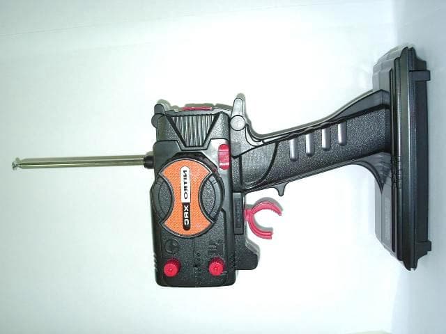
AEKA54095
Oct 14, 2007REMOTE CONTROL TRANSMITTER
Equipment Class
TNB - Licensed Non-Broadcast Station Transmitter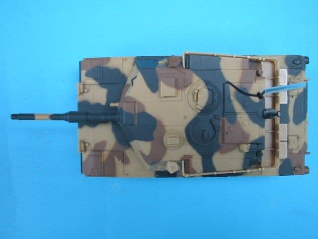
AEKA73049R
Sep 04, 2007BATTLE TANK
Equipment Class
CRR - Superregenerative Receiver
AEKA56349R
Dec 10, 200649MHz RECEIVER
Equipment Class
CRR - Superregenerative Receiver
AEKA56327
Dec 06, 200627 MHz TRANSMITTER
Equipment Class
DXX - Part 15 Low Power Communication Device Transmitter
AEKA56349
Dec 06, 200649MHz TRANSMITTER
Equipment Class
DXX - Part 15 Low Power Communication Device Transmitter