AEKA40349jet helio-transmitter
Taiyo Co., Ltd.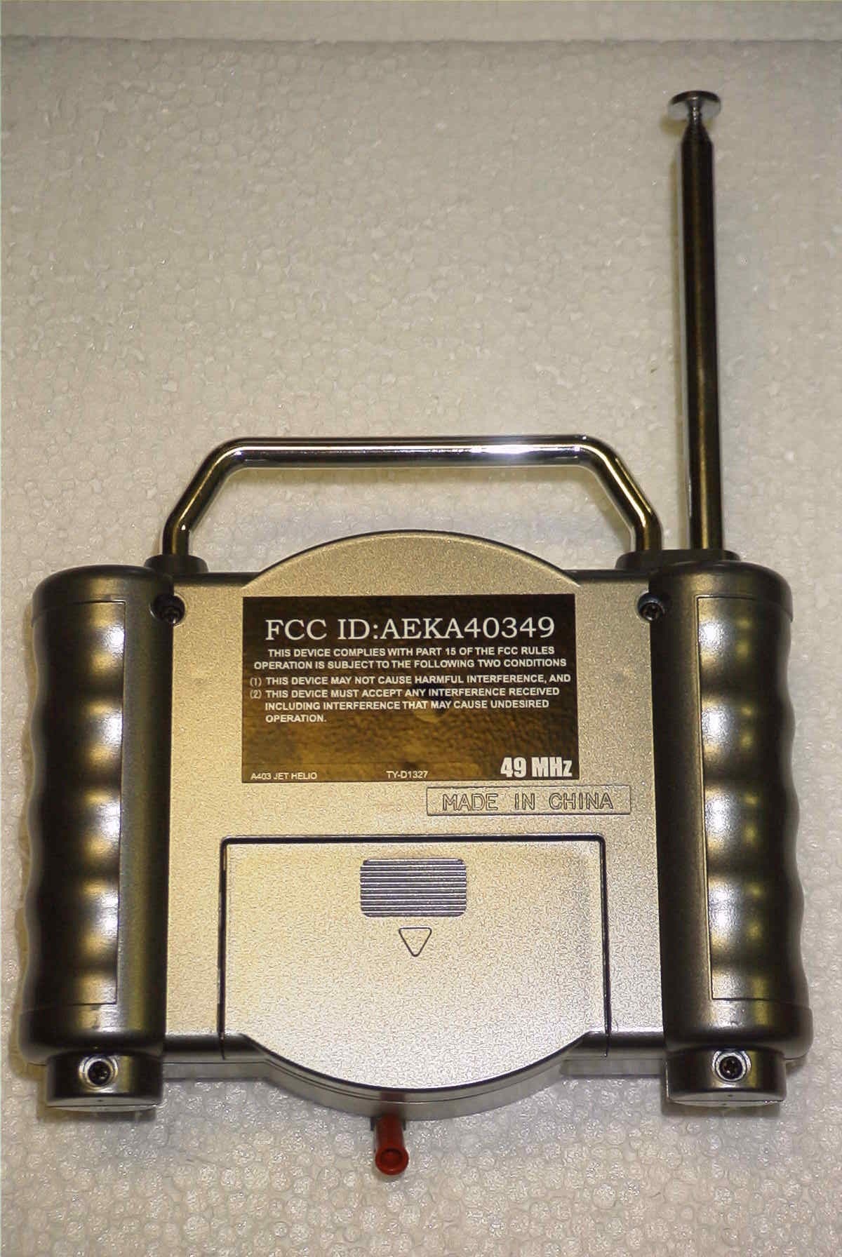
Click to zoom
Application Details
- Equipment Class
- DXX - Part 15 Low Power Communication Device Transmitter
- Date of Grant
- May 17, 2004
- Application Purpose
- Original Equipment
- Date of Application
- May 17, 2004
- Equipment Note
- jet helio-transmitter
- Frequency Range
- 49.82000000 - 49.90000000
- Company
- Taiyo Co., Ltd.
- Country
- Japan
Documents & Files
Document Text
Text extracted from the exhibit documents filed with the FCC. Open a document above to read the original.
Users Manual
HELICOPTER R/C • This helicopter is the first in the industry that can be turned in the right and left direc- tions with simple operation of the transmitter. • Rigid structural design and materials are used. • The power is automatically shut off gradually when the helicopter is out of the radio wave range to prevent the helicopter from dropping suddenly. HELIO_En_cover.p654/9/04, 10:01 AM1 English 2 BEFORE USING THE PRODUCT Thank you for purchasing this TAIYO product. Please read this owner’s manual thoroughly to get the most use from the helicopter and to learn how to operate it safely. Also, keep this manual with you when using the helicopter. ! WARNING Be sure to read the following. If the 7.2 V Ni-MH battery pack is used incorrectly, it may over- heat, explode, or start a fire. Pay attention to the following items. • Be sure to follow the charging instructions in this manual. • Do not try to charge any battery pack other than the included 7.2 V Ni-MH battery pack. • After playing with the helicopter, be sure to turn off the switch. • If the battery pack is short-circuited, a large current will flow and this is a dangerous situation. Do not ever short-circuit the battery pack. • Never drop the battery pack into water, throw it into a fire or disassemble it. • Do not use, charge, or store the battery pack near a fire or in any place where exposed to high temperatures or high humidity. • When using the 7.2 V Ni-MH battery pack for the first time, be sure to charge it. Even if the 7.2 V Ni-MH battery pack is not used, it will self-discharge over time. If the battery pack has not been used for about six months, be sure to charge the battery pack before using the product. Once the battery pack is charged, make sure to use it until it is completely dead be- fore recharging it. • Even when the battery pack has been charged correctly, if the flying time is noticeably reduced, the 7.2 V Ni-MH battery pack may have reached the limit of its useful life. • If the 7.2 V Ni-MH battery pack is still warm after use, do not recharge it. • Do not recharge the battery pack within reach of infants or children. • Do not recharge the 7.2 V Ni-MH battery pack once it is al- ready recharged. The battery pack may become very warm. • Use the dedicated charger to recharge the 7.2 V Ni-MH bat- tery. If you use a cigarette lighter inside the car to recharge the 7.2 V Ni-MH battery pack, pay attention to the following items. • Do not recharge the power pack while you are driving. • The inside of the cigarette lighter socket becomes hot after you use it to light the cigarette. Use the cigarette lighter socket after it becomes sufficiently cool. • Do not pull the cable to remove the cigarette lighter plug. Do- ing so may break the cable. • In some cars, recharging can be performed after removing the key from the car. Remove the cigarette lighter plug from the socket and stop recharging when you leave the car. • Soon after playing with the helicopter, the included 7.2 V Ni- MH power pack becomes hot. Be sure to cool down the in- cluded 7.2 V Ni-MH power pack before recharging it again. In recharging, the cigarette lighter plug, charger body and the included 7.2 V Ni-MH power pack will have a little heat, but this phenomenon is not an indication of trouble. • Do not get the 7.2 V Ni-MH power pack or the charger body wet. Doing so may cause malfunction. In addition, never throw the included power pack into a fire, disassemble it or short- circuit it. • Leave the engine running while recharging the 7.2 V Ni-MH power pack. • When a child recharges the 7.2 V Ni-MH power pack, an adult with a valid driver’s license should be with the child until the battery is charged and the power pack is disconnected. Also, do not recharge the power pack within reach of infants or young children. • Do not recharge or leave the battery pack in any place where exposed to strong direct sunlight. • Be sure to remove the charger from the car when the battery is not used. • The cigarette lighter plug is for exclusive use with cars that have a 12 V cigarette lighter (accessory socket). This plug cannot be used in cars with a 24 V or 100 V cigarette lighter. If the batteries for the charger (D alkaline batteries / TAIYO 9.6 V Power Pack) and transmitter (006P-9 V battery) are used in- correctly, they may overheat, explode, start a fire, or let electro- lyte leak. Pay attention to the following items. • Never use the charger as a DC power source for any other purpose. Never recharge the power pack using any other charger. • Use eight D alkaline batteries for the charger. • Use a 006P-9 V battery for the transmitter. • Never use a rechargeable battery such as a Ni-Cd battery. • Do not use a combination of new and old batteries or different kinds of batteries. • Turn off power to the charger before replacing the batteries. • Set the batteries so that the and are correctly positioned. • Be sure to remove the batteries after use. • Never short-circuit the batteries, charge them, heat them, throw them into a fire, or disassemble them. • If any electrolyte from the battery is splashed into an eye, immediately flush it with clean water and consult a physician. If the electrolyte gets on your skin or clothes, wash it off with water. • When you use the TAIYO 9.6 V Power Pack to recharge the batteries, follow the instructions on the manual of the charger set. Precautions when playing with the helicopter • After use, never store the helicopter within reach of the chil- dren under 3 years of age. • Incorrect use of the helicopter may cause an accident. Do not let children 15 years old or younger operate the helicopter. Children should operate the helicopter only under the super- vision of an adult. • Play with the helicopter in a wide-open, safe location with no obstacles nearby. Do not fly the helicopter in a place where other people or animals are nearby. • Do not launch the helicopter toward another person. Some one may be injured. • Never store the helic…
Text truncated - open the document above for the full version.
Operational Description
TAIYO KOGYO CO., LTD. SUBJECT: Circuit Descripton Reference: FCCID: AEKA40349 The A40349 transmitter is made up of the two stage RF section. The crystal Oscillator Q2 is a bipolar transistor. The signal from the Crystal oscillator is fed through the tuned circuit made up of L1 & C4 and then coupled to the output stage Q3. From Q3 the signal is coup[led to a tuned circuit made up of L2 and then coupled to a low pass filter through C13. The low pass filter is made up of C14, L3, and C15. Modulation for this unit is pulse position and this is provided by IC1, the modulation is varied by the switches, S2, S3, S4 & S5. Form Letters6 Rev 25 June03
Test Report
TIMCO ENGINEERING INC. 849 NW State Road 45 Newberry, Florida 32669 http://www.timcoengr.com 888.472.2424 F 352.472.2030 email: [email protected] APPLICANT: TAIYO KOGYO CO., LTD. Test Report Product Name: JET HELIO - TRANSMITTER FCC ID: AEKA40349 Applicant: TAIYO KOGYO CO., LTD. NO 1-23-17, HIGASHIYOTSUGI KATSUSHIKA-KU TOKYO 124 JAPAN Date Receipt: APRIL 26, 2004 Date Tested: MAY 11, 2004 FCC ID: AEKA40349 REPORT #: T\Taiyo_AEK\593JT4\593JT4TestReport.doc COVER SHEET TIMCO ENGINEERING INC. 849 NW State Road 45 Newberry, Florida 32669 http://www.timcoengr.com 888.472.2424 F 352.472.2030 email: [email protected] APPLICANT: TAIYO KOGYO CO., LTD. TABLE OF CONTENTS LIST APPLICANT: TAIYO KOGYO CO., LTD. FCC ID: AEKA40349 TEST REPORT CONTAINING: PAGE 1.............TEST EQUIPMENT LIST PAGE 2.............TEST PROCEDURE PAGE 3.............RADIATION INTERFERENCE TEST DATA PAGE 4.............OCCUPIED BANDWIDTH PAGE 5.............OCCUPIED BANDWIDTH PLOT EXHIBITS INCLUDING: BLOCK DIAGRAM SCHEMATIC INSTRUCTION MANUAL LABEL SAMPLE LABEL LOCATION EXTERNAL PHOTOGRAPHS INTERNAL PHOTOGRAPHS CIRCUIT DESCRIPTION TEST SET UP PHOTOGRAPH FCC ID: AEKA40349 REPORT #: T\Taiyo_AEK\593JT4\593JT4TestReport.doc TABLE OF CONTENTS TIMCO ENGINEERING INC. 849 NW State Road 45 Newberry, Florida 32669 http://www.timcoengr.com 888.472.2424 F 352.472.2030 email: [email protected] APPLICANT: TAIYO KOGYO CO., LTD. Equipment List Device Manufacturer Model Serial Number Cal/Char Date Due Date 3/10-Meter OATS TEI N/A N/A Listed 3/27/04 3/26/07 3-Meter OATS TEI N/A N/A Listed 1/13/03 1/13/06 Biconnical Antenna Eaton 94455-1 1057 CAL 3/18/03 3/18/05 Biconnical Antenna Eaton 94455-1 1096 CAL 10/1/01 10/1/03 Biconnical Antenna Electro- Metrics BIA-25 1171 CAL 4/26/01 4/26/03 Blue Tower Quasi-Peak Adapter HP 85650A 2811A01279 CAL 4/15/03 4/15/05 Blue Tower RF Preselector HP 85685A 2620A00294 out for Cal Blue Tower Spectrum Analyzer HP 8568B 2928A04729 2848A18049 CAL 4/15/03 4/15/05 LISN Electro- Metrics ANS-25/2 2604 CAL 10/9/01 10/9/03 LISN Electro- Metrics EM-7820 2682 CAL 3/12/03 3/12/05 Log- Periodic Antenna Eaton 96005 1243 CAL 5/8/03 5/8/05 FCC ID: AEKA40349 REPORT #: T\Taiyo_AEK\593JT4\593JT4TestReport.doc Page 1 of 5 TIMCO ENGINEERING INC. 849 NW State Road 45 Newberry, Florida 32669 http://www.timcoengr.com 888.472.2424 F 352.472.2030 email: [email protected] APPLICANT: TAIYO KOGYO CO., LTD. TEST PROCEDURE GENERAL: This report shall NOT be reproduced except in full without the written approval of TIMCO ENGINEERING, INC. RADIATION INTERFERENCE: The test procedure used was ANSI STANDARD C63.4-1992 using a HEWLETT PACKARD spectrum analyzer with a pre-selector. The bandwidth of the spectrum analyzer was 100 kHz with an appropriate sweep speed. The analyzer was calibrated in dB above a microvolt at the output of the antenna. The resolution bandwidth was 100 kHz and the video bandwidth was 300 kHz. The ambient temperature of the UUT was 80ºC with a humidity of 76%. FORMULA OF CONVERSION FACTORS: The Field Strength at 3m was established by adding the meter reading of the spectrum analyzer (which is set to read in units of dBuV) to the antenna correction factor supplied by the antenna manufacturer. The antenna correction factors are stated in terms of dB. The gain of the Pre- selector was accounted for in the Spectrum Analyzer Meter Reading. Example: Freq (MHz) METER READING + ACF = FS 33 20 dBuV + 10.36 dB = 30.36 dBuV/m @ 3m ANSI STANDARD C63.4-1992 10.1.7 MEASUREMENT PROCEDURES: The unit under test was placed on a table 80 cm high and with dimensions of 1m by 1.5m. The table used for radiated measurements is capable of continuous rotation. When an emission was found, the table was rotated to produce the maximum signal strength. At this point, the antenna was raised and lowered from 1m to 4m. The antenna was placed in both the horizontal and vertical planes. FCC ID: AEKA40349 REPORT #: T\Taiyo_AEK\593JT4\593JT4TestReport.doc Page 2 of 5 TIMCO ENGINEERING INC. 849 NW State Road 45 Newberry, Florida 32669 http://www.timcoengr.com 888.472.2424 F 352.472.2030 email: [email protected] APPLICANT: TAIYO KOGYO CO., LTD. APPLICANT: TAIYO KOGYO CO., LTD. FCC ID: AEKA40349 NAME OF TEST: RADIATION INTERFERENCE RULES PART NO.: 15.235 REQUIREMENTS: CARRIER FREQUENCY WILL NOT EXCEEDS 80 dBuV/m AT 3M. OUT-OF-BAND EMISSIONS SHALL NOT EXCEED: 30 - 88 MHz 40.0 dBuV/M MEASURED AT 3 METERS 88 - 216 MHz 43.5 dBuV/M 216 - 960 MHz 46.0 dBuV/M ABOVE 960 MHz 54.0 dBuV/M TEST DATA: Emission Frequency MHz Meter Reading dBuV Ant. Polarity Coax Loss dB Correction Factor dB Field Strength dBuV/m Margin dB 49.88 53.1 H 0.97 11.63 65.70 14.30 49.88 67.7 V 0.97 10.82 79.45 0.55 99.71 19.8 H 1.40 10.50 31.70 11.80 99.71 29.9 V 1.40 11.32 42.62 0.88 149.58 0.5 H 1.75 15.77 18.02 25.48 149.58 3.5 V 1.75 16.96 22.21 21.29 199.50 7.8 H 2.10 16.64 26.54 16.96 199.50 15.0 V 2.10 17.44 34.54 8.96 249.31 13.0 V 2.35 12.46 27.81 18.19 299.19 1.3 V 2.60 13.62 17.52 28.48 349.07 4.9 V 2.85 14.69 22.44 23.56 448.78 8.6 V 3.30 18.27 30.17 15.83 498.66 4.9 V 3.49 17.90 26.29 19.71 SAMPLE CALCULATION: FSdBuV/m = MR (dBuV) + ACFdB. TEST PROCEDURE: The procedure used was ANSI STANDARD C63.4-1992. The spectrum was scanned from 30 MHz to 1000 MHz. When an emission was found, the table was rotated to produce the maximum signal strength. The antenna was placed in both the horizontal and vertical planes and the worse case emissions were reported. The UUT was tested in 3 orthogonal planes. TEST RESULTS: THE UNIT DOES MEET THE FCC REQUIREMENTS. PERFORMED BY: SID SANDERS DATE: MAY 11, 2004 FCC ID: AEKA40349 REPORT #: T\Taiyo_AEK\593JT4\593JT4TestReport.doc Page 3 of 5 TIMCO ENGINEERING INC. 849 NW State Road 45 Newberry, Florida 32669 http://www.timcoengr.com 888.472.2424 F 352.472.2030 email: [email protected] APPLICANT: TAIYO KOGYO CO., LTD. APPLICANT: TAIYO KOGYO CO., LTD. FCC ID: AEKA40349 NAME OF TEST: Occupied Bandwidth RULES PART NO.: 15.235 REQUIREMENTS: The field strength of any emis…
Text truncated - open the document above for the full version.
Contact Information
Applicant
Hiroyuki Sasaki(Manager of Quality Assurance Section)
Test Firm
Timco Engineering, Inc.Sid Sanders
Technical Specifications
| # | Rule Parts | Frequency Range | Power Output |
|---|---|---|---|
| 1 | 15C | 49.82 MHz - 49.9 MHz | - |
Other Applications from Taiyo Co., Ltd.
AEKA54095
Oct 14, 2007REMOTE CONTROL TRANSMITTER
Equipment Class
TNB - Licensed Non-Broadcast Station Transmitter
AEKA73049R
Sep 04, 2007BATTLE TANK
Equipment Class
CRR - Superregenerative Receiver
AEKA56349R
Dec 10, 200649MHz RECEIVER
Equipment Class
CRR - Superregenerative Receiver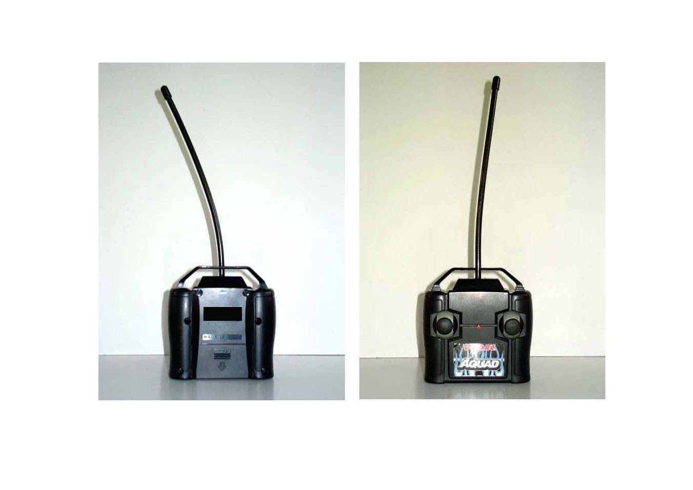
AEKA56327
Dec 06, 200627 MHz TRANSMITTER
Equipment Class
DXX - Part 15 Low Power Communication Device Transmitter
AEKA56349
Dec 06, 200649MHz TRANSMITTER
Equipment Class
DXX - Part 15 Low Power Communication Device Transmitter