AEKA50749RBATTLE TANK - RECEIVER
Taiyo Co., Ltd.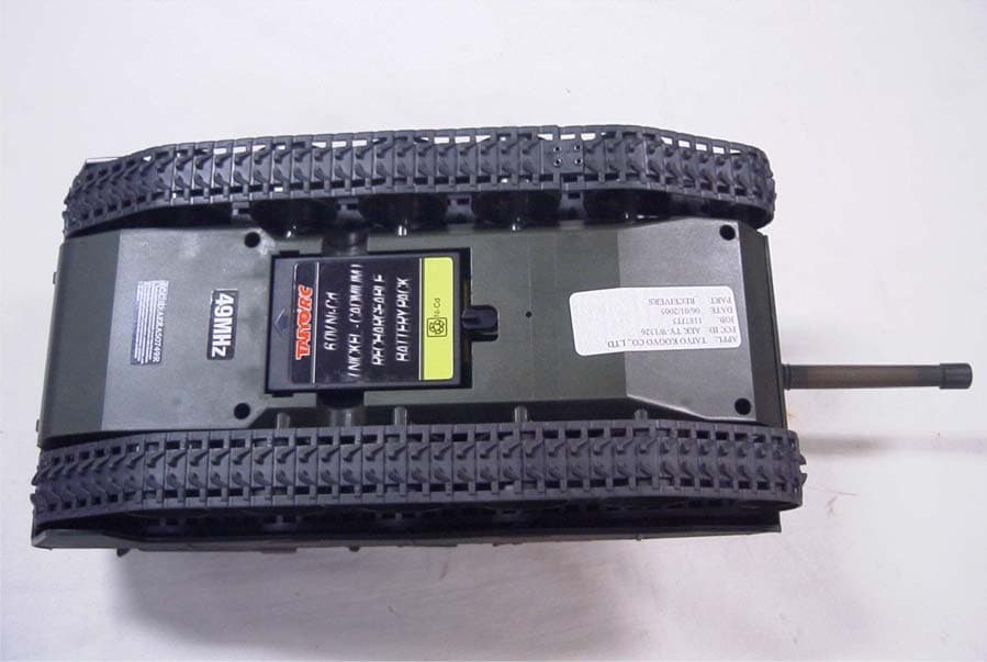
Click to zoom
Application Details
- Equipment Class
- CRR - Superregenerative Receiver
- Date of Grant
- Jun 22, 2005
- Application Purpose
- Original Equipment
- Date of Application
- Jun 22, 2005
- Equipment Note
- BATTLE TANK - RECEIVER
- Frequency Range
- 49.82000000 - 49.90000000
- Company
- Taiyo Co., Ltd.
- Country
- Japan
Documents & Files
Document Text
Text extracted from the exhibit documents filed with the FCC. Open a document above to read the original.
Users Manual
ENG OWNER’S MANUAL Keep these instructions for future reference as they contain important information.x-c-v-b,n-m 638A507-01 2005.06.15, 14:52Page 3 2 q w qq qq q ww ww w ee ee e qq qq q ww ww w ee ee e ABED C qq qq q ww ww w rr rr r tt tt t yy yy y ENG OWNER’S MANUAL Keep these instructions for future reference as they contain important information. x-c-v-b,n-m 638A507-01 2005.06.15, 16:07Page 2 3 q w qq qq q ww ww w ee ee e qq qq q ww ww w ee ee e 2005.06.15, 16:07Page 3 4 ww ww w qq qq q ee ee e rr rr r yy yy y tt tt t ii ii i uu uu u 2005.06.15, 16:08Page 4 5 qw er qq qq q ee ee e 2005.06.15, 16:08Page 5 ENG 6 Please check the headings I - V with the diagrams in pages 2, 3, 4, 5. I. CONTENTS & FEATURES This kit includes: A. Octo Spinner 360° B. Transmitter C. 9.6V battery pack D. Battery charger E. Manual qOcto Spinner 360 ° (Side View) qBody wWheel eOn/Off Switch wTransmitter qTransmitter Antenna wControl Stick for Left Side Wheel eControl Stick for Right Side Wheel rUp Button tDown Button yPower Indicator There is no on/off switch on Transmitter. Moving the sticks turns it on automati- cally. II. BATTERY INSTALLATION qTransmitter To remove, reverse the installation pro- cedure qSlide open the battery door in the direc- tion as shown in the figure, while lightly pressing its center. wInsert a 9V (006P) battery with the polari- ty (+/-) as shown on the bottom of battery compartment. eReplace battery door, following the remov- al procedure in reverse. w Octo Spinner 360 ° This product should be used with adult supervision. Fully charge 9.6V battery pack in advance of your use qTurn the latches on vehicle battery door to unlock and open. wInsert 9.6V battery pack into battery com- partment with correct polarity (+/-). eClose battery door, turn the latches to lock. III. BEFORE OPERATION Turn vehicle power on. On/Off Switch is on the rear of the vehi- cle. IV. THROTTLE CONTROLS qFORWARD (Push both sticks forward.) wREVERSE THRUST (Pull both sticks back.) eLEFT TURN (FORWARD) (Push right stick forward.) rRIGHT TURN (FORWARD) (Push left stick forward.) tLEFT SPIN (At the same time, pull left stick back and push right stick forward.) yRIGHT SPIN (At the same time, pull right stick back and push left stick forward.) uFolding (Press the Up button.) iUnfolding (Press the Down button.) ONE-WHEEL SPINNING The vehicle spins on either of its front wheels like a top. q Push the Up button to fold the vehicle's body. w The vehicle starts spinning (i.e., spin turn- ing) with the small-wheel side down. e When the vehicle is spinning, push both sticks of the transmitter forward (both sides forward) at the same time. r The vehicle starts one-wheel spinning. V. CAUTIONS DURING PLAYING WITH VEHICLE qDo not drive your vehicle on streets or in a crowded place. wWhen 9.6V battery pack gets wet, dry com- pletely to store. eDo not store the vehicle in a place near a heater or like where temperature rises. After use, remove the batteries from trans- mitter and vehicle to store. rThis vehicle is not water-proofed. Immers- ing it into water may lead to a malfunc- tion. Dry vehicle well after operating on water. BATTERY SAFETY INFORMATION Batteries may leak fluids that can cause a chemical burn injury or ruin your toy (prod- uct). To avoid battery leakage: • Insert batteries as indicated inside the bat- tery compartment. • Remove batteries during long periods of non-use. Always remove exhausted batter- ies from the toy (product). Dispose batter- ies safely. • Do not dispose the batteries in a fire. They may explode or leak. • Never short-circuit the battery terminals. • Use only batteries of the same or equiva- lent type, as recommended. • Do not charge non-rechargeable batteries. • If removable, rechargeable batteries are used in the Octo Spinner 360° and/or trans- mitter, they are only to be charged under adult supervision. IMPORTANT INFORMATION • DO NOT RECHARGE THE BATTERY IF IT FEELS HOT. ALLOW IT TO COOL BE- FORE RECHARGING. • NOT ATTEMPT TO USE OR CHARGE THE BATTERY IF IT SHOWS SIGNS OF LEAK- AGE OR CORROSION. • DO NOT DISASSEMBLE THE BATTERY. • IF THE OCTO SPINNER 360° BATTERY AND TRANSMITTER ARE WET, THOR- OUGHLY DRY BEFORE USING OR CHARGING. • REGULARLY EXAMINE ALL WIRES AND CONNECTORS. IN THE EVENT OF DAM- AGE, DO NOT USE. Important: • If driving time becomes shorter or wheels do not turn with full power, the capacity of the 9.6V battery pack are insufficient. (Pow- er LED light becomes dimmer as batteries wear.) It is the tell-tale sign you need to re- place the 9.6V battery pack. • Be sure to recharge the Octo Spinner 360° just before driving it. If you do not play with the Octo Spinner 360° immediately after re- charging, the charge is drained and the Octo Spinner 360° cannot drive. • When the battery temperature gets too high, the circuit shuts off automatically to protect the receiver circuit and the battery in the •Octo Spinner 360°. In such a case, wait until 2005.06.15, 16:08Page 6 ENG 7 TROUBLESHOOTING GUIDE Make sure the vehicle power is on. Make sure the batteries in transmitter and vehicle have sufficient charge. Check if the batteries in transmitter and vehicle are inserted with correct polarity. Check if the distance between trans- mitter and vehicle will not exceed more than 65’/20m. Two or more vehicles of the same fre- quency will interference with each oth- er. In such a case, move to another place or try after a while. NOTE: The manufacturer is not responsible for any radio or TV interference caused by unauthorized modifications to this equipment. Such modifications could void the user's authority to op- erate the equipment. the battery cools down before recharging or playing with the Octo Spinner 360°. •If the rechargeable battery is repeatedly charged without being sufficiently dis- charged first, the capacity will gradually de- crease (memory effect of battery). This is a characteristic of rechargeable batteries. Be sure to start recharging after operating the vehicle until they nea…
Text truncated - open the document above for the full version.
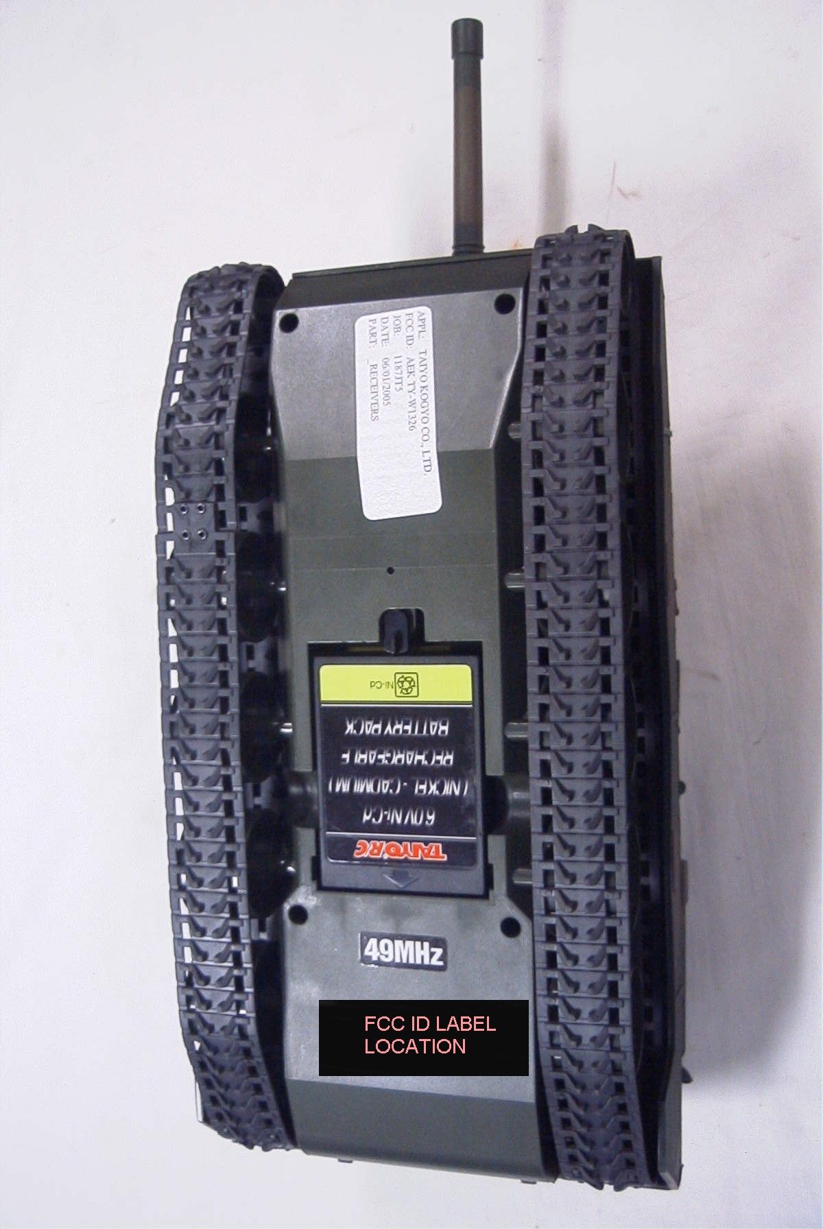
External Photos
TAIYO KOGYO CO., LTD. FCC ID: AEKA50749R EXTERNAL PHOTOGRAPHS
Internal Photos
TAIYO KOGYO CO., LTD. FCC ID: AEKA50749R INTERNAL PHOTOGRAPHS
Operational Description
Circuit Description for Receiver Q1 is a Common Base RF amplifier used as part of a super regenative receiver. L1 and C2 comprise the tuned circuit set for 49.86 MHz.. IC1 (RX5C) contains all the demodulator and motor driver electronics. Three motor are driven by three diferent H pattern transistor driver circuits. Energy is supplied to the receiver and motors via a 6V battery. 1187JT5
Test Report
TIMCO ENGINEERING INC. 849 NW State Road 45 Newberry, Florida 32669 http://www.timcoengr.com 888.472.2424 F 352.472.2030 email: [email protected] APPLICANT: TAIYO KOGYO CO., LTD. FCC ID: AEKA50749R REPORT #: U:\T\Taiyo_AEK\1187JT5\1187JT5 TestReport.DOC COVER SHEET TITLE PAGE TIMCO ENGINEERING, INC. TEST REPORT APPLICANT: TAIYO KOGYO CO., LTD. NO 1-23-17, HIGASHIYOTSUGI KATSUSHIKA-KU TOKYO 124 JAPAN FCC ID: AEKA50749R DESCRIPTION OF BATTLE TANK RECEIVER SAMPLE TESTED: 49.82-49.90 MHz DATE SAMPLE RECEIVED FOR TESTING: 6/1/2005 DATE TESTED: 6/7/2005 PLEASE NOTE: THE ATTACHED REPORT SHALL NOT BE REPRODUCED EXCEPT IN FULL WITHOUT THE WRITTEN APPROVAL OF TIMCO ENGINEERING, INC. TIMCO ENGINEERING INC. 849 NW State Road 45 Newberry, Florida 32669 http://www.timcoengr.com 888.472.2424 F 352.472.2030 email: [email protected] APPLICANT: TAIYO KOGYO CO., LTD. FCC ID: AEKA50749R REPORT #: U:\T\Taiyo_AEK\1187JT5\1187JT5 TestReport.DOC TABLE OF CONTENTS TABLE OF CONTENTS LIST APPLICANT: TAIYO KOGYO CO., LTD. FCC ID: AEKA50749R TEST REPORT CONTAINING: PAGE 1...............TEST EQUIPMENT LIST PAGE 2...............TEST PROCEDURES PAGE 3...............RADIATION INTERFERENCE TEST DATA PAGE 4...............TEST SETUP PHOTO EXHIBITS CONTAINING: BLOCK DIAGRAM SCHEMATIC INSTRUCTION MANUAL LABEL SAMPLE LABEL LOCATION EXTERNAL PHOTOGRAPHS INTERNAL PHOTOGRAPHS CIRCUIT DESCRIPTION TEST SET UP PHOTOGRAPH TIMCO ENGINEERING INC. 849 NW State Road 45 Newberry, Florida 32669 http://www.timcoengr.com 888.472.2424 F 352.472.2030 email: [email protected] APPLICANT: TAIYO KOGYO CO., LTD. FCC ID: AEKA50749R REPORT #: U:\T\Taiyo_AEK\1187JT5\1187JT5 TestReport.DOC Page 1 of 4 EMC Equipment List Device Manufacturer Model Serial Number Cal/Char Date Due Date 3/10-Meter OATS TEI N/A N/A Listed 3/27/04 3/26/07 3-Meter OATS TEI N/A N/A Listed 1/13/03 1/12/06 Biconnical Antenna Eaton 94455-1 1057 CAL 3/18/03 3/18/05 Biconnical Antenna Eaton 94455-1 1096 CAL 10/1/01 10/1/03 Biconnical Antenna Electro- Metrics BIA-25 1171 CAL 4/26/01 4/26/03 Blue Tower Quasi-Peak Adapter HP 85650A 2811A01279 CAL 4/15/03 4/15/05 Blue Tower RF Preselector HP 85685A 2620A00294 CAL 4/27/04 4/27/06 Blue Tower Spectrum Analyzer HP 8568B 2928A04729 2848A18049 CAL 4/15/03 4/15/05 LISN Electro- Metrics ANS-25/2 2604 CAL 10/9/01 10/9/03 LISN Electro- Metrics EM-7820 2682 CAL 3/12/03 3/12/05 Log- Periodic Antenna Eaton 96005 1243 CAL 5/8/03 5/8/05 TIMCO ENGINEERING INC. 849 NW State Road 45 Newberry, Florida 32669 http://www.timcoengr.com 888.472.2424 F 352.472.2030 email: [email protected] APPLICANT: TAIYO KOGYO CO., LTD. FCC ID: AEKA50749R REPORT #: U:\T\Taiyo_AEK\1187JT5\1187JT5 TestReport.DOC Page 2 of 4 TEST PROCEDURE GENERAL: This report shall NOT be reproduced except in full without the written approval of TIMCO ENGINEERING, INC. RADIATION INTERFERENCE: The test procedure used was ANSI STANDARD C63.4-2003 using a HEWLETT PACKARD spectrum analyzer with a preselector. The bandwidth of the spectrum analyzer was 100 kHZ with an appropriate sweep speed. The analyzer was calibrated in dB above a microvolt at the output of the antenna. The resolution bandwidth was 100KHZ and the video bandwidth was 300KHZ. The ambient temperature of the UUT was 80ºF with a humidity of 70%. FORMULA OF CONVERSION FACTORS: The Field Strength at 3m was established by adding the meter reading of the spectrum analyzer (which is set to read in units of dBuV) to the antenna correction factor supplied by the antenna manufacturer. The antenna correction factors are stated in terms of dB. The gain of the Preselector was accounted for in the Spectrum Analyzer Meter Reading. Example: Freq (MHz) METER READING + ACF = FS 33 20 dBuV + 10.36 dB = 30.36 dBuV/m @ 3m ANSI STANDARD C63.4-2003 10.1.7 MEASUREMENT PROCEDURES: The unit under test was placed on a table 80 cm high and with dimensions of 1m by 1.5m. The table used for radiated measurements is capable of continuous rotation. When an emission was found, the table was rotated to produce the maximum signal strength. At this point, the antenna was raised and lowered from 1m to 4m. The antenna was placed in both the horizontal and vertical planes. TIMCO ENGINEERING INC. 849 NW State Road 45 Newberry, Florida 32669 http://www.timcoengr.com 888.472.2424 F 352.472.2030 email: [email protected] APPLICANT: TAIYO KOGYO CO., LTD. FCC ID: AEKA50749R REPORT #: U:\T\Taiyo_AEK\1187JT5\1187JT5 TestReport.DOC Page 3 of 4 APPLICANT: TAIYO KOGYO CO., LTD. FCC ID: AEKA50749R NAME OF TEST: RADIATION INTERFERENCE RULES PART NO.: 15.109 REQUIREMENTS: 30 to 88 MHz: 40.0 dBuV/M @ 3 METERS 88 to 216 MHz: 43.5 dBuV/M 216 to 960 MHz: 46.0 dBuV/M ABOVE 960 MHz: 54.0 dBuV/M TEST RESULTS: A search was made of the spectrum from 30 to 1000MHz and the measurements indicate that the unit DOES meet the FCC requirements. TEST DATA: Tuned Frequency MHz Emission Frequency MHz Meter Reading dBuV Ant. Polarity Coax Loss dB Correction Factor dB Field Strength dBuV/m Margin dB 49.8 47.60 21.8 V 0.49 10.62 32.91 7.09 49.8 47.60 22.4 H 0.49 11.20 34.09 5.91 49.8 51.10 21.0 V 0.50 11.25 32.75 7.25 49.8 51.10 22.5 H 0.50 11.20 34.20 5.80 49.8 53.20 16.2 V 0.51 11.55 28.26 11.74 49.8 53.20 19.2 H 0.51 11.20 30.91 9.09 49.8 92.70 21.0 V 0.63 10.15 31.78 11.72 49.8 92.70 24.6 H 0.63 8.85 34.08 9.42 SAMPLE CALCULATION: FSdBuV/m = MR (dBuV) + ACFdB. TEST PROCEDURE: ANSI STANDARD C63.4-2003 12.1.1.1 SUPERREGENERATIVE RECEIVER: A Signal Generator was set to the unit under test operating frequency. An un-modulated continuous wave (CW) signal was radiated at the super regenerative receiver operating frequency to cohere the characteristic broadband emissions from the receiver. PERFORMED BY: JOSEPH SCOGLIO DATE: June 7, 2005 TIMCO ENGINEERING INC. 849 NW State Road 45 Newberry, Florida 32669 http://www.timcoengr.com 888.472.2424 F 352.472.2030 email: [email protected] APPLICANT: TAIYO KOGYO CO., LTD. FCC ID: AEKA50749R REPORT #: U:\T\Taiyo_AEK\1187JT5\1187JT5 TestReport.DOC Page 4 of 4 APPLICANT: …
Text truncated - open the document above for the full version.
Contact Information
Applicant
Hiroyuki Sasaki(Manager of Quality Assurance Section)
Test Firm
Timco Engineering, Inc.Sid Sanders
Technical Specifications
| # | Rule Parts | Frequency Range | Power Output |
|---|---|---|---|
| 1 | 15B | 49.82 MHz - 49.9 MHz | - |
Other Applications from Taiyo Co., Ltd.
AEKA54095
Oct 14, 2007REMOTE CONTROL TRANSMITTER
Equipment Class
TNB - Licensed Non-Broadcast Station Transmitter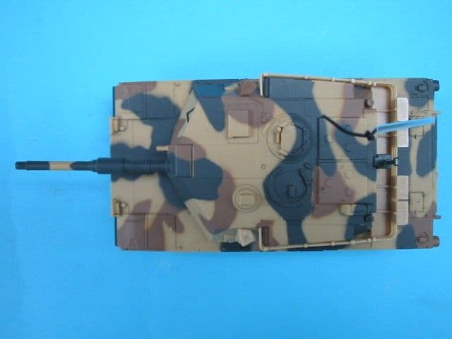
AEKA73049R
Sep 04, 2007BATTLE TANK
Equipment Class
CRR - Superregenerative Receiver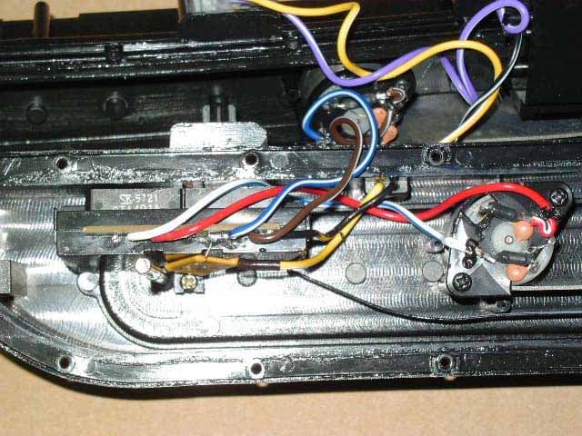
AEKA56349R
Dec 10, 200649MHz RECEIVER
Equipment Class
CRR - Superregenerative Receiver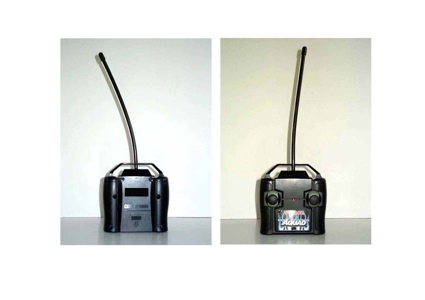
AEKA56327
Dec 06, 200627 MHz TRANSMITTER
Equipment Class
DXX - Part 15 Low Power Communication Device Transmitter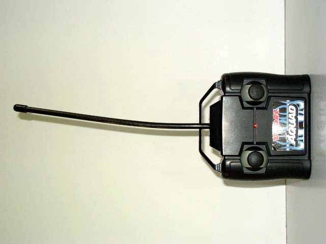
AEKA56349
Dec 06, 200649MHz TRANSMITTER
Equipment Class
DXX - Part 15 Low Power Communication Device Transmitter