AEKA5142727MHz REMOTE CONTROL TRANSMITTER
Taiyo Co., Ltd.
Click to zoom
Application Details
- Equipment Class
- DXX - Part 15 Low Power Communication Device Transmitter
- Date of Grant
- Sep 26, 2006
- Application Purpose
- Original Equipment
- Date of Application
- Sep 26, 2006
- Equipment Note
- 27MHz REMOTE CONTROL TRANSMITTER
- Frequency Range
- 27.00000000 - 27.00000000
- Company
- Taiyo Co., Ltd.
- Country
- Japan
Documents & Files
Document Text
Text extracted from the exhibit documents filed with the FCC. Open a document above to read the original.
Users Manual
638A508-01 ENG OWNER’S MANUAL Keep these instructions for futu re refe rence as they contain important information. A458RM250_638A508-012006.07.10, 21:19Page 3Adobe PageMaker 6.5J/PPC 2 638A508-01 ENG x-c-v-b,n-m-, OWNER’S MANUAL Keep these instructions for future reference as they contain important information. q w qq qq q ww ww w ee ee e rr rr r qq qq q ww ww w ee ee e q A BE D C tt tt t yy yy y uu uu u ii ii i rr rr r tt tt t yy yy y qq qq q ww ww w 2006.07.11, 13:32Page 2 3 qq qq q ww ww w ee ee e w q qq qq q ww ww w qq qq q-1 ww ww w-1 qq qq q qq qq q-1 ww ww w ee ee e-1 rr rr r ee ee e rr rr r-1 2006.07.11, 13:32Page 3 4 w qq qq q-1 qq qq q-2 ww ww w-1 ww ww w-2 ee ee e e qq qq q qq qq q-1 qq qq q-2 2006.07.11, 13:32Page 4 5 65 ́/20m ee ee e ww ww w qq qq q-3 r 2006.07.11, 13:32Page 5 6 Precaution Safety first CAUTION: TO AVOID BATTERY LEAKAGE. (OF BUILT-IN LiPoly RECHARGEABLE BATTERIES) • Charge batteries following the battery and charger manufacturer's instructions. • Charge batteries with the included charger at the first use. • Do not charge batteries with a charger other than the included one. • Do not charge batteries other than the built-in LiPoly battery with the included charger or use the charger as the power source for other equipment. • Do not charge batteries in a place within the reach of small children. • Do not give an impact to batteries and the charger during charging • Do not re-peak a LiPoly battery that has peaked, otherwise the battery may be degraded. LiPoly batteries have a low natural discharge rate, it does not require recharging in the first one or 2 hours after a charge. • When charge is complete, unplug the charger from the wall outlet. • After use, be sure to turn the switch off. Failure to do so may adversely affect batter- ies, resulting in disabled charge. • Do not short circuit battery terminals, otherwise the battery may swell and get hot, leading to a danger. • Do not wet batteries, heat, disassemble or modify them. Do not dispose of batteries in fire. • Do not use, store or charge batteries in a place near a heater, or in high temperature or humidity condition. • When the use out of batteries becomes shorter and shorter, it is most likely time to replace the battery. Contact our service representative in such a case. CAUTION: TO AVOID BATTERY LEAKAGE. (OF 9-VOLT (006P) RECHARGEABLE BATTERIES FOR TRANSMITTER) • Use 006P-9V dry batteries for transmitter. • Make sure the batteries are inserted with correct polarity and follow the toy and battery manufacturer's instructions. • After use, remove the batteries from the transmitter to store. • Battery replacement should be done in presence of adult. • Do not attempt to short-circuit, disassemble or heat batteries. Do not dispose of batteries in fire or wet them. • If battery fluid contacts your eyes, skin or cloths, immediately wash them with water and consult a doctor. Precautions before Flight Depending on flight condition or due to improper control, flying a helicopter can be hazardous resulting in unforeseen accidents such as bodily injury and property dam- age, and the helicopter operator shall be held responsible for such accident. To be a responsible operator, you are recommended to obtain adequate insurance before playing with the helicopter. CAUTIONS DURING PLAYING • For avoiding hazards from improper use, this helicopter is not intended for children under 15 years old. Also, children are recommended to use this helicopter under adult's supervision. • Do not touch charging terminals (i.e., the metal part) on the helicopter body and the charger. • Make sure you have plenty of open space in all directions (at least 3m-radius from your location). Fly the helicopter in a safe area away from people, pets, etc. • Check if a near transmitter produces interference or signals with the same fre- quency. In such a case, move to another place or try after a while. • Do not point the transmitter antenna toward a person's or animal's head, otherwise an unforeseen accident may occur. Also, do not bend the antenna. • Do not throw the helicopter toward a person or animal, otherwise an injury may occur. • Do not bend or pull the components with a strong force. • Do not keep looking at the blinking LEDs on the transmitter and the helicopter body. Doing so may cause you to feel uncomfortable. • Never attempt to disassemble or modify the helicopter. • Do not bring your face or hands near the rotating rotor. For safety's sake, you are recommended to wear goggles. • Keep supervision to the helicopter in flight. • Do not operate the rotor while it is locked. • Do not drop or impact. • Do not use an helicopter if it is unrecoverably damaged or distorted. • After use, store the helicopter in a place out of the reach of children 3 years old or younger. • Do not store the helicopter in a place near a heater or like where temperature rises (e.g., a shut up car in summer). Battery Disposal Instructions THIS PRODUCT USES A LITHIUM POLYMER BATTERY. MUST BE RECYCLED OR DISPOSED PROPERLY. Contact your local area office of solid waste management or other appropriate local agency for information. Do not attempt to disassemble the battery before disposal. ENG 2006.07.11, 13:33Page 6 ENG 7 Please check the headings I - VI with the diagrams in pages 2, 3, 4, 5. I. CONTENTS & FEATURES This kit includes: A. Micro Master x 1 B. Transmitter x 1 C. Charger x 1 D. Transmitter antenna x 1 E. Manual x 1 The product shown in the figure may slightly differ from the real ones. q Micro Master q Rotor * The rotor has a play structure for safety, but not completely fixed. When the rotor starts rotating, the centrifugal force acts on the rotor allowing it to operate normally. w Tail fin e Antenna * Do not cut the antenna rods. r Charging port / Power switch (at the bottom) t 3.7V LiPoly battery embedded y Skid u Body i Safety ring w Transmitter Front q Antenna w Throttle Stick e Adjustment Knob r Switch t Rudder stick (left/right) / Forward stick…
Text truncated - open the document above for the full version.
Operational Description
Circuit description for AEKA51427 This device is a crystal controlled pulse position modulated transmitter. The oscillator consists of the combination of Q1 and XL1. Q2, Q3 and it’s associated circuitry act as a buffer amplifier for the oscillator. The pi filter consisting of T3, C25, and C26 act as a harmonic filter and antenna matching circuit. Modulation is provide by IC1(ST7LITE15B). Energy to this device is supplied by a single 9Volt battery. The antenna is removable 5 elements rod antenna.
Test Report
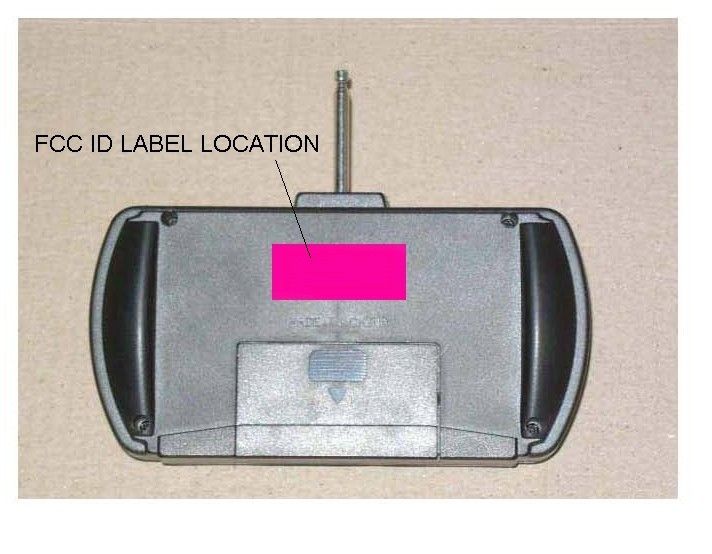
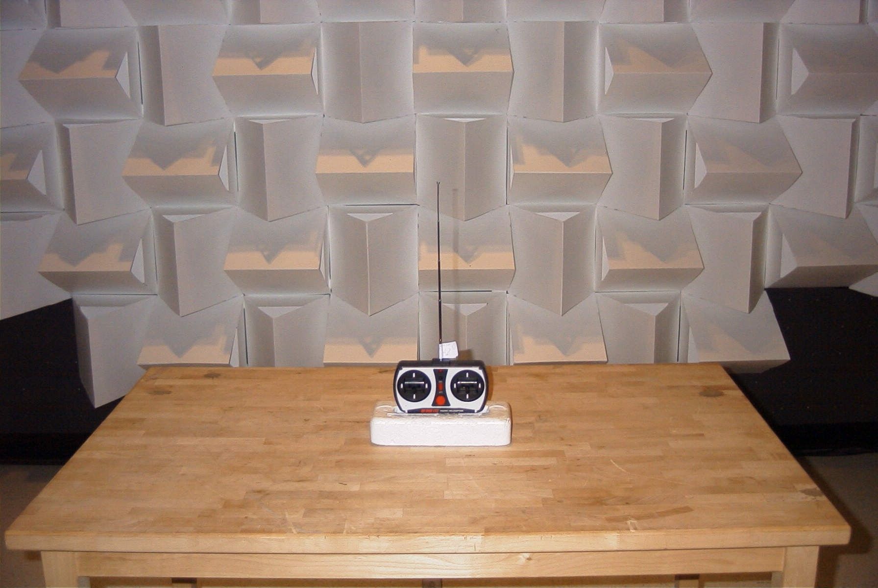
TIMCO ENGINEERING INC. 849 NW State Road 45 Newberry, Florida 32669 http://www.timcoengr.com 888.472.2424 F 352.472.2030 email: [email protected] APPLICANT: TAIYO KOGYO CO., LTD. FCC ID: AEKA51427 REPORT #: T\Taiyo_AEK\2581JT6\2581JT6TestReport.doc COVER SHEET Test Report Product Name: 27 MHZ REMOTE CONTROL TRANSMITTER FCC ID: AEKA51427 Applicant: TAIYO KOGYO CO., LTD. FUKOKUSEIMEI BLDG. 6F, NO. 1-2-11 KAMINARIMON, TAITO-KU TOKYO 111-0034 JAPAN Date Receipt: 9/8/2006 Date Tested: 9/11/2006 TIMCO ENGINEERING INC. 849 NW State Road 45 Newberry, Florida 32669 http://www.timcoengr.com 888.472.2424 F 352.472.2030 email: [email protected] APPLICANT: TAIYO KOGYO CO., LTD. FCC ID: AEKA51427 REPORT #: T\Taiyo_AEK\2581JT6\2581JT6TestReport.doc TABLE OF CONTENTS TABLE OF CONTENTS LIST APPLICANT: TAIYO KOGYO CO., LTD. FCC ID: AEKA51427 TEST REPORT CONTAINING: PAGE 1...............TEST EQUIPMENT LIST PAGE 2...............TEST PROCEDURE PAGE 3...............RADIATION INTERFERENCE TEST DATA PAGE 4...............OCCUPIED BANDWIDTH PAGE 5...............TEST SET UP PHOTO EXHIBITS INCLUDING: BLOCK DIAGRAM SCHEMATIC INSTRUCTION MANUAL LABEL SAMPLE LABEL LOCATION EXTERNAL PHOTOGRAPHS INERNAL PHOTOGRAPHS OPERATIONAL DESCRIPTION TEST SET UP PHOTOGRAPHS TIMCO ENGINEERING INC. 849 NW State Road 45 Newberry, Florida 32669 http://www.timcoengr.com 888.472.2424 F 352.472.2030 email: [email protected] APPLICANT: TAIYO KOGYO CO., LTD. FCC ID: AEKA51427 REPORT #: T\Taiyo_AEK\2581JT6\2581JT6TestReport.doc Page 1 of 5 EMC Equipment List Device Manufacturer Model Serial Number Cal/Char Date Due Date 3/10-Meter OATS TEI N/A N/A Listed 3/27/04 3/26/07 3-Meter OATS TEI N/A N/A Listed 1/11/06 1/10/09 Antenna: Biconnical Eaton 94455-1 1057 CAL 12/12/05 12/12/07 Antenna: Biconnical Eaton 94455-1 1096 Out for Cal Antenna: Biconnical Electro-Metrics BIA-25 1171 CAL 4/29/05 4/29/07 Analyzer Blue Tower Quasi- Peak Adapter HP 85650A 2811A01279 CAL 4/13/05 4/13/07 Analyzer Blue Tower RF Preselector HP 85685A 2926A00983 CAL 9/5/05 9/5/07 Analyzer Blue Tower Spectrum Analyzer HP 8568B 2928A04729 2848A18049 CAL 4/13/05 4/13/07 LISN Electro-Metrics EM-7820 2682 CAL 4/28/05 4/28/07 Antenna: Log- Periodic Eaton 96005 1243 CAL 12/14/05 12/14/07 Antenna: Active Loop ETS-Lindgren 6502 00062529 CAL 3/30/06 3/30/08 Antenna: Passive Loop EMC Test Systems EMCO 6512 9706-1211 CAL 4/27/06 4/27/08 TIMCO ENGINEERING INC. 849 NW State Road 45 Newberry, Florida 32669 http://www.timcoengr.com 888.472.2424 F 352.472.2030 email: [email protected] APPLICANT: TAIYO KOGYO CO., LTD. FCC ID: AEKA51427 REPORT #: T\Taiyo_AEK\2581JT6\2581JT6TestReport.doc Page 2 of 5 TEST PROCEDURE GENERAL: This report shall NOT be reproduced except in full without the written approval of TIMCO ENGINEERING, INC. RADIATION INTERFERENCE: The test procedure used was ANSI STANDARD C63.4- 2003 using a HEWLETT PACKARD spectrum analyzer with a pre-selector. The bandwidth of the spectrum analyzer was 100 kHz with an appropriate sweep speed. The analyzer was calibrated in dB above a microvolt at the output of the antenna. The resolution bandwidth was 100 kHz and the video bandwidth was 300 kHz. The ambient temperature of the UUT was 80ºC with a humidity of 76%. FORMULA OF CONVERSION FACTORS: The Field Strength at 3m was established by adding the meter reading of the spectrum analyzer (which is set to read in units of dBuV) to the antenna correction factor supplied by the antenna manufacturer. The antenna correction factors are stated in terms of dB. The gain of the Pre-selector was accounted for in the Spectrum Analyzer Meter Reading. Example: Freq (MHz) METER READING + ACF = FS 33 20 dBuV + 10.36 dB = 30.36 dBuV/m @ 3m ANSI STANDARD C63.4-2003 10.1.7 MEASUREMENT PROCEDURES: The unit under test was placed on a table 80 cm high and with dimensions of 1m by 1.5m. The table used for radiated measurements is capable of continuous rotation. When an emission was found, the table was rotated to produce the maximum signal strength. At this point, the antenna was raised and lowered from 1m to 4m. The antenna was placed in both the horizontal and vertical planes. TIMCO ENGINEERING INC. 849 NW State Road 45 Newberry, Florida 32669 http://www.timcoengr.com 888.472.2424 F 352.472.2030 email: [email protected] APPLICANT: TAIYO KOGYO CO., LTD. FCC ID: AEKA51427 REPORT #: T\Taiyo_AEK\2581JT6\2581JT6TestReport.doc Page 3 of 5 APPLICANT: TAIYO KOGYO CO., LTD. FCC ID: AEKA51427 NAME OF TEST: RADIATION INTERFERENCE RULES PART NO.: 15.227 REQUIREMENTS: CARRIER FREQUENCY WILL NOT EXCEEDS 80 dBuV/m AT 3M. OUT-OF-BAND EMISSIONS SHALL NOT EXCEED: 30 - 88 MHz 40.0 dBuV/M MEASURED AT 3 METERS 88 - 216 MHz 43.5 dBuV/M 216 - 960 MHz 46.0 dBuV/m ABOVE 960 MHz 54.0 dBuV/m TEST DATA: Emission Frequency MHz Meter Reading dBuV Ant. Pol Coax Loss dB Correction Factor dB Field Strength dBuV/m Margin dB 27.00 32.3 H 0.40 34.18 66.88 13.12 27.00 40.9 V 0.40 34.18 75.48 4.52 53.99 9.5 H 0.51 11.20 21.21 18.79 54.00 18.5 V 0.51 11.66 30.67 9.33 81.00 3.5 H 0.60 6.72 10.82 29.18 81.00 7.0 V 0.60 6.92 14.52 25.48 107.97 15.6 V 0.66 12.39 28.65 14.85 107.98 9.9 H 0.66 12.20 22.76 20.74 134.97 7.6 V 0.68 13.00 21.28 22.22 134.98 2.8 H 0.68 13.10 16.58 26.92 161.97 5.0 V 0.75 15.25 21.00 22.50 188.97 2.8 H 0.86 17.34 21.00 22.50 188.97 3.1 V 0.86 17.38 21.34 22.16 215.96 12.3 H 0.93 11.66 24.89 18.61 215.97 22.2 V 0.93 11.40 34.53 8.97 242.97 18.8 H 0.99 12.15 31.94 14.06 242.97 29.8 V 0.99 12.08 42.87 3.13 269.98 18.9 H 1.04 13.50 33.44 12.56 269.98 30.1 V 1.04 13.30 44.44 1.56 SAMPLE CALCULATION: FSdBuV/m = MR (dBuV) + ACFdB. All measurements below 30 MHz were taken using an EMC Test Systems Passive Loop Antenna. TEST PROCEDURE: The procedure used was ANSI STANDARD C63.4-2003. The spectrum was scanned from 30 MHz to 1000 MHz. When an emission was found, the table was rotated to produce the maximum signal strength. The antenna was placed in both the horizontal and vertical planes and the worse case emissions were reported. The UUT…
Text truncated - open the document above for the full version.
Contact Information
Applicant
Hiroyuki Sasaki(Manager of Quality Assurance Section)
Test Firm
Timco Engineering, Inc.Sid Sanders
Technical Specifications
| # | Rule Parts | Frequency Range | Power Output |
|---|---|---|---|
| 1 | 15C | 27 MHz - 27 MHz | - |
Other Applications from Taiyo Co., Ltd.
AEKA54095
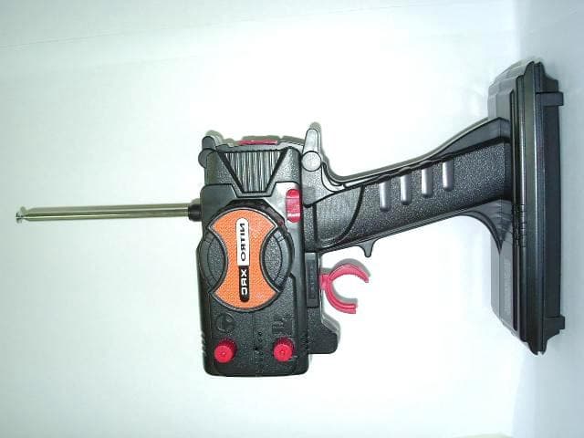
Oct 14, 2007REMOTE CONTROL TRANSMITTER
Equipment Class
TNB - Licensed Non-Broadcast Station Transmitter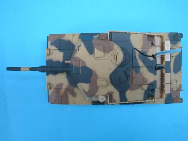
AEKA73049R
Sep 04, 2007BATTLE TANK
Equipment Class
CRR - Superregenerative Receiver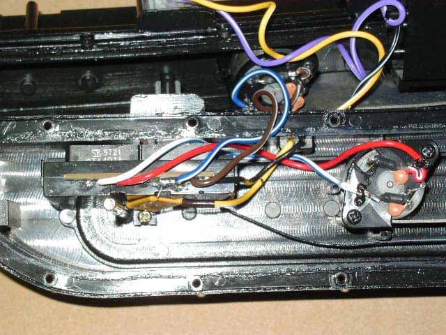
AEKA56349R
Dec 10, 200649MHz RECEIVER
Equipment Class
CRR - Superregenerative Receiver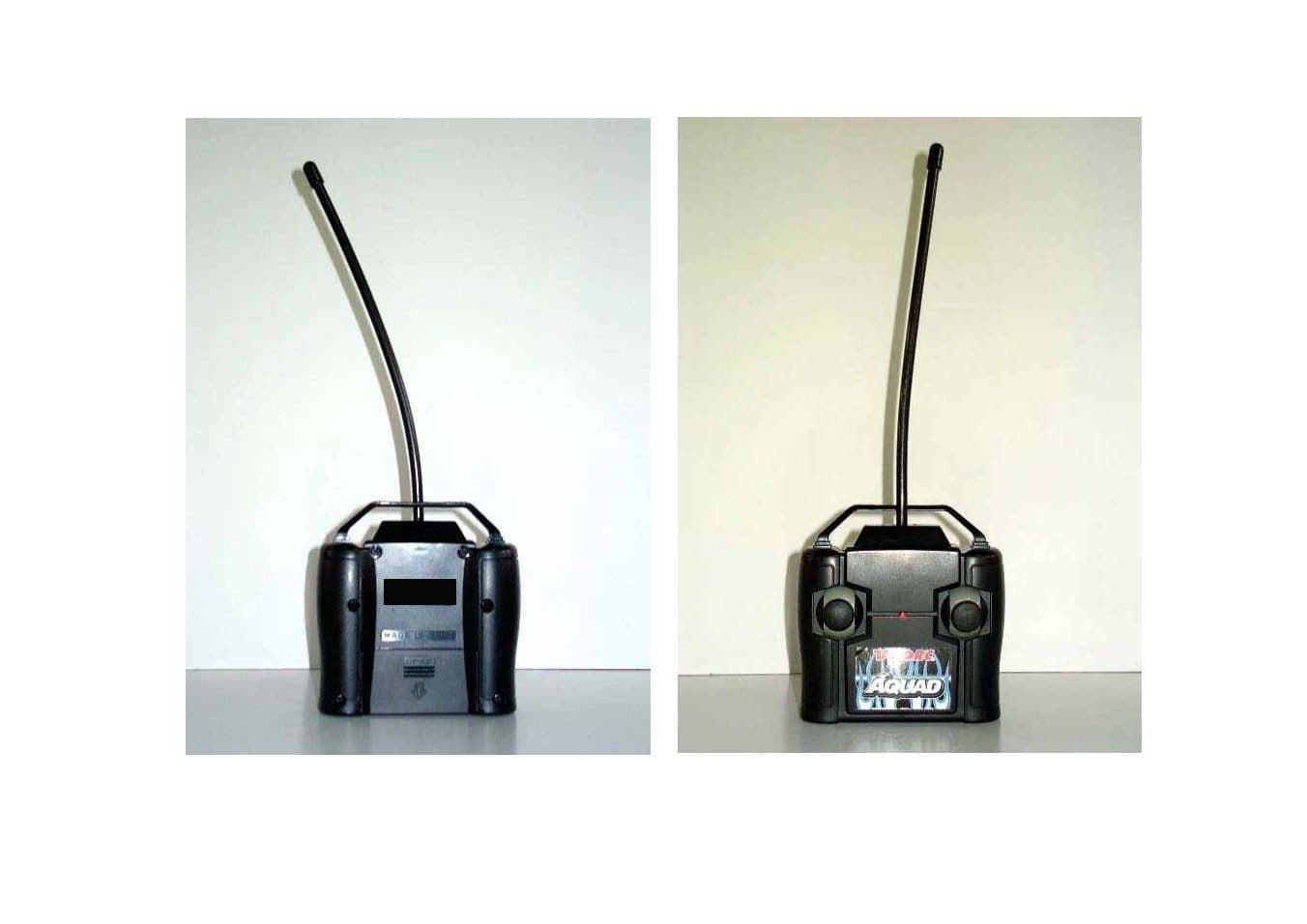
AEKA56327
Dec 06, 200627 MHz TRANSMITTER
Equipment Class
DXX - Part 15 Low Power Communication Device Transmitter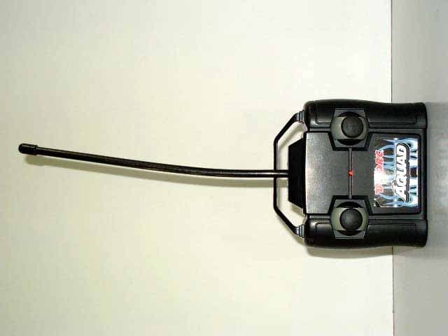
AEKA56349
Dec 06, 200649MHz TRANSMITTER
Equipment Class
DXX - Part 15 Low Power Communication Device Transmitter