AEZPBS-CS100PHS Cell Station
Sanyo Electric Co Ltd
Click to zoom
Application Details
- Equipment Class
- PCB - PCS Licensed Transmitter
- Date of Grant
- Jun 17, 2004
- Application Purpose
- Original Equipment
- Date of Application
- Jun 17, 2004
- Equipment Note
- PHS Cell Station
- Frequency Range
- 1880.00000000 - 1910.00000000
- Company
- Sanyo Electric Co Ltd
- Country
- United States
Documents & Files
Document Text
Text extracted from the exhibit documents filed with the FCC. Open a document above to read the original.
Users Manual
SANYO PHS Cell Station March 19, 2004 - User’s Manual - 1 Table of Contents Installation co nditions ....................................................................................................... .......... 2,3 Fixing antenna for PBS-CS100 .................................................................................................. .... 4 Condition of the antenna cable (PBS-CS100) .............................................................................. 5Terminal block appearance ..................................................................................................... ....... 6 Notes at the time of lid opening and closing ................................................................................. 7 Connection of the power cable ............................................................................................... 8 ,9,10 Connection of the line cable ............................................................................................... 11 ,12,13 Concerning the installa tion of cable .......................................................................................... .. 14 Warning ....................................................................................................................... .................. 15 Appendix (1), (2) ............................................................................................................. ......... 16,17 2 Installation conditions ] Place \ CS shall be installed in the place where the public can not easily access. \ Installation place shall have the structure which can support the weight of CSand its fixing facilities. \ Installation place shall be flat with no inclination. \ If CS is installed in the place where it may drop down, it shall be provided with protective measure against the drop. \ There shall be no object around 2m of CS. \ For the maintenance use, there shall be the space in about 500mm around thestand. \ CS shall be installed in the direction that the logo plate appears upwards. CScan be placed in vertical direction with arranging the fixing metal. 3 Installation conditions ] Antenna \ With fixing antennas, there shall be enough viewing angle from CS. (Targetangle: vertical: 30 degree or more, horizontal: 330 degree or more) ] ISDN Line \ Interconnection box for ISDN line shall be available near the CS. \ ISDN line length from the exchange to CS and its quality shall comply with the technical standard (ANSI T1.601-1992). ] Power supply \ AC120V shall be available with easy wiring connection work. 4 Fixing antenna for PBS-CS100 To ISDN Line AC120V MDFBreaker PBS-CS100 5 Condition of the antenna cable(PBS-CS100) ] Numbering arrangement \ Numbering arrangement of 1 - 4 shall be madeclockwise or counterclockwise. ] Tightening torque of the antenna cable:7 - 12 Kgf-cm. ] Wind the self-bonding tape between theantenna connector and the end of cable. 1 2 3 4 1 2 3 4 Case of Clockwise Case of Counterclockwise 6 Terminal block appearance(PBS-CS100) ] Terminal block of the power supply a nd line’s connections are shown below 1: Status indications LED2: Reset Switch3: Maintenance terminal connector4,5: Line Status LED6: Power supply Terminal7: Earth clamp for Power cable8: Cable gland for power cable 9: Cable gland for Line cable10: Power supply switch11: Fuse12: Earth clamp for Line cable13,14: Line terminal connector 1 2 3 4 5 6 7 8 9 10 11 12 13 14 7 Notes at the time oflid opening and closing ] Opening \ After loosening all lid’s fixation screws completely, pulllower part and central scre w of the lid, and slide. (Photo1) \ Confirm that all screws are free completely and two pins ofthe lid is at the right edge of two metal fittings ,therefore rotate the lid while pulling in the direction”an arrow” likebelow . (Photo2) ] Closing \ Tightening torque of Cap screw: 10 - 15 Kgf-cm \ Tighten with M4 hexagon Sock et Cap screws. (Cap screw). \ Tighten 6 screws equally and well balanced, after confirming that the waterproof packing is nonexistent between the lid and the CS. [Caution1] If the clamp face or waterproof packing is scarred by screw’s cusp, the waterp roof performance may not be obtained. (Photo1) (Photo2) 8 Connection of the power cable (1) 1) Reeve the cable from the cable gland nut into the lid. 2) Pull the cable out to enough length that the tip of the cable can be processed. 3) Peel the covering of the cable. (Photo 3)4) Peeling off core line.5) Loosen the copper shield and wind it onto the core wire’s tip 4 turns or more. (Photo3) Copper shield Covering end Covering 70 - 90mm interposition material: Cut it at the covering’ root. (figure) 8 - 9mm 60 - 80mm 15mm Copper shield *The cable color is generally used in Japan, and itused in U.S.A. shall comply with the local specifications. 9 Connection of the power cable (2) 6) Turn the Power supply switch off.(Photo4) \ Push the power supply switch at " ○ "side to turn it off. \ [Caution] When pushing the power switch at "-"side, CS is turned on. (photo4) P u s h 10 Connection of the power cable (3) 7) Feazings processing of the core line. \ Pressing the black portion of the connectorwith a minus screwdriver( φ 6) or a plus screwdriver( φ 4) , insert a core wire. \ L (Loading), N (Neutral), FG (Frame Ground). 8) Combine the copper shield to the position “FIX” of Photo 5. And tighten the cablegland firmly. \ [Caution] If the fixation of the terminal block’s lid is imperfect, it is feared that this CS gives hindrance to other electric devices. N:White FG:Red L:Black F o r m i n g (photo5) 9) Form core wires that are insert ed into the power supply terminal. 10) The tightening of the dome nut must be done by hand without fail and tighten it strongly. 11) Wind the self-bonding tape between the surface of dome nut and the end of cable. Fix Press with a screwdriver 11 Connection of the line cable (1) 1) Reeve the cable from the dome nut into the lid. 2) Pull the line cable out to enough length that the tip of the cable c…
Text truncated - open the document above for the full version.
External Photos
1 Body: Front View 2 Body: Back View 3 Body: Bottom View 4 Body: Left-side View 5 Body: Top View 6 Body: Right-side View 7 Body: Close-up of Label (Bottom) 8 Body: Right-side View (Inside)
ID Label/Location Info
SN FCC ID: AEZPBS-CS100 52 21
ID Label/Location Info
FCC ID LABEL
Internal Photos
1 Inside view Left: Power unit Right:GPS interface (top), 2 DSU (under GPS interface), control board (middle), sealed board and mounting terminal (bottom) 2 Inside view GPS interface (right), 2 DSU (under GPS interface), control board (under DSU), sealed board and mounting terminal (left) 3 Inside view (under GPS interface) 2 DSU (right), control board (under DSU), sealed board and mounting terminal (left) 4 Inside view (under DSU) Control board (center), mounting terminal (left) 5 Inside view (under control board) RFMB board (with sealed case, center), mounting board (left) 6 Inside view (under RFMB board) 2 Front end module (center), mounting terminal (left) 7 Bottom case 8 Inside view (with mounting terminal) * Left side of the case (page no.: 7) 9 Power unit (Power module with cover) 10 Power module (without cover) 11Power unit (SENDAN, Power module with cover) 12Power module (SENDAN, without cover) 13GPS interface (front view) GPS interface circuit for SANYO (left) GPS interface circuit for TRIMBLE (right) 14GPS interface (back view) GPS interface circuit for SANYO (left) GPS interface circuit for TRIMBLE (right) 15DSU (front view) 16 DSU (back view) 17 Control board (front view) 17-1 17-2 17-3 17-4 17-1 *Control board –front view (Part 1) 17-2 *Control board – front view (Part 2) 17-3 *Control board – front view (Part 3) 17-4 *Control board – front view (Part 4) 18 Control board (back view) 18-1 18-2 18-3 18-4 18-1 *Control board –back view (Part 1) 18-2 *Control board –back view (Part 2) 18-3 *Control board –back view (Part 3)
Internal Photos
18-4 *Control board –back view (Part 4)
Internal Photos
19Mounting terminal (inside of the case) 20Mounting terminal (outside of the case) 21RFMB board (with sealed case, front view) 22 RFMB board (with sealed case, back view) 23 RFMB board (front view) 23-1 23-2 23-3 23-4 23-1 *RFMB board –front view (Part 1) 23-2 *RFMB board –front view (Part 2) 23-3 *RFMB board –front view (Part 3) 23-4 *RFMB board –front view (Part 4) 24RFMB board (back view) 24-1 24-2 24-3 24-4 24-1 *RFMB board –back view (Part 1) 24-2*RFMB board –back view (Part 2) 24-3 *RFMB board –back view (Part 3) 24-4 *RFMB board –back view (Part 4) 25RFMB local module (without cover) 26 Front end module (with cover) 27 Front end module (without cover, front view) 28 Front end module (back view)
Test Report
A-008-04-C Page 1 of 59 KEC Ikoma Testing Laboratory 12128 Takayama Ikoma-City Nara 630-0101 Japan KANSAI ELECTRONIC INDUSTRY DEVELOPMENT CENTER HEAD OFFICE IKOMA TESTING LABORATORY 6-8-7 NISHITENMA 12128 TAKAYAMA-CHO KITA-KU OSAKA 530-0047 JAPAN IKOMA-CITY NARA 630-0101 JAPAN Corporate Juridical Person TEST REPORT Report No.A-008-04-C Date: 14 June 2004 This test report is to certify that the tested device properly complies with the requirements of: FCC Rules and Regulations Part 24 Personal Communications Services. All the tests necessary to show compliance to the requirements were performed and these results met the specifications of requirement. The results of this report should not be construed to imply compliance of equipment other than that, which was tested. Unless the laboratory permission, this report should not be copied in part. 1. Applicant Company Name : SANYO Electric Co., Ltd. Mailing Address : 1-1, Sanyo-cho, Daito-shi, Osaka, 574-8534 Japan 2. Identification of Tested Device Type of Device : PHS Cell Station Type of Modulation : : Narrowband PCS : Broadband PCS Kind of Equipment Authorization : : DoC : Certification : Verification FCC ID : AEZPBS-CS100 Device Name : PHS Cell Station Trade Name : SANYO Model Number : PBS-CS100 Serial Number : UTS00001 : Prototype : Pre-production : Production Date of Manufacture : May 2004 3. Test Items and Procedure : RF Conducted Power Measurement : Antenna Conducted Spurious Emission Measurement : Transmit Power (EIRP) Measurement : Radiated Spurious (EIRP) Measurement : Occupied Bandwidth Measurement : Band Edge RF Conducted Emission Measurement : Frequency Stability Measurement : Radiated Emission Measurement : AC Power Line Conducted Emission Measurement Above all tests were performed under: FCC Part 2, 24 and ANSI C63.4 – 2001 : without deviation, : with deviation(details are found inside of this report) 4. Date of Test Receipt of Test Sample : 26 May 2004 Condition of Test Sample : : Damage is not found on the set. : Damage is found on the set. (Details are described in this report) Test Completed on : 2 June 2004 Seiichi Izumi General Manager/ Ikoma Testing Laboratory A-008-04-C Page 2 of 59 KEC Ikoma Testing Laboratory 12128 Takayama Ikoma-City Nara 630-0101 Japan Table of Contents 0. LABORATORY ACCREDITATION AND MEASUREMENT UNCERTAINTY ..................... 3 0.1. Laboratory Accreditation .................................................................................................... 3 0.2. Measurement Uncertainty ................................................................................................. 3 1. CERTIFICATION OF THE COMPLIANCE ........................................................................... 3 2. GENERAL INFORMATION ................................................................................................... 4 2.1. Product Description ............................................................................................................ 4 2.2. Description for Equipment Authorization ......................................................................... 5 2.3. Test Facility......................................................................................................................... 5 3. TESTED SYSTEM ..................................................................................................................6 3.1. Test Mode ............................................................................................................................ 6 3.2. Characterization and condition of EUT System ................................................................ 6 3.3. Test Configuration .............................................................................................................. 7 3.4. Block Diagram of EUT System......................................................................................... 11 3.5. Test Arrangement on Radiated Spurious Emission Measurement................................. 12 3.6. List of EUT System........................................................................................................... 13 3.7. List of Cables..................................................................................................................... 13 4. RF CONDUCTED POWER MEASUREMENT (§ 2.1046 (a) ))................................................. 14 4.1. Test Procedure................................................................................................................... 14 4.2. Test Results ....................................................................................................................... 15 5. ANTENNA CONDUCTED SPURIOUS EMISSION MEASUREMENT (§24.238)................. 18 5.1. Test Procedure................................................................................................................... 18 5.2. Test Results ....................................................................................................................... 19 6. TRANSMIT POWER (E. I. R. P) MEASUREMENT (§ 24.232)............................................... 27 6.1. Test Procedure ...................................................................................................................... 27 6.2. Test Results ........................................................................................................................... 28 7. RADIATED SPURIOUS (E. I. R. P) MEASUREMENT (§ 24.238).......................................... 32 7.1. Test Procedure ...................................................................................................................... 32 7.2. Test Results ........................................................................................................................... 33 8. OCCUPIED BANDWIDTH MEASUREMENT (§ 2.1049, §24.238)............................................... 41 8.1. Test Procedure .................................................................…
Text truncated - open the document above for the full version.
Test Setup Photos
A-008-04-C Page 1 of 4 FCC ID: AEZPBS-CS100 KEC Ikoma Testing Laboratory 12128 Takayama-cho Ikoma-city Nara 630-0101 Japan 1. APPENDIX Photographs of EUT System Configuration Tested Item ・ Transmit Power (EIRP) measurement ・ Radiated Spurious (EIRP) measurement ・ Radiated Emission measurement FRONT VIEW A-008-04-C Page 2 of 4 FCC ID: AEZPBS-CS100 KEC Ikoma Testing Laboratory 12128 Takayama-cho Ikoma-city Nara 630-0101 Japan - Continued – REAR VIEW A-008-04-C Page 3 of 4 FCC ID: AEZPBS-CS100 KEC Ikoma Testing Laboratory 12128 Takayama-cho Ikoma-city Nara 630-0101 Japan Tested Item ・Conducted Emission measurement A-008-04-C Page 4 of 4 FCC ID: AEZPBS-CS100 KEC Ikoma Testing Laboratory 12128 Takayama-cho Ikoma-city Nara 630-0101 Japan - Continued -
Contact Information
Applicant
Hideaki Mukaida
Test Firm
Kansai Electronic Industry Dev. Ct.Eizo Hariya
Technical Specifications
| # | Rule Parts | Frequency Range | Power Output | Emission | Tolerance |
|---|---|---|---|---|---|
| 1 | 24E | 1.88 GHz - 1.91 GHz | 53.7 W | 290KDXW | 3.0000000000 ppm |
Other Applications from Sanyo Electric Co Ltd
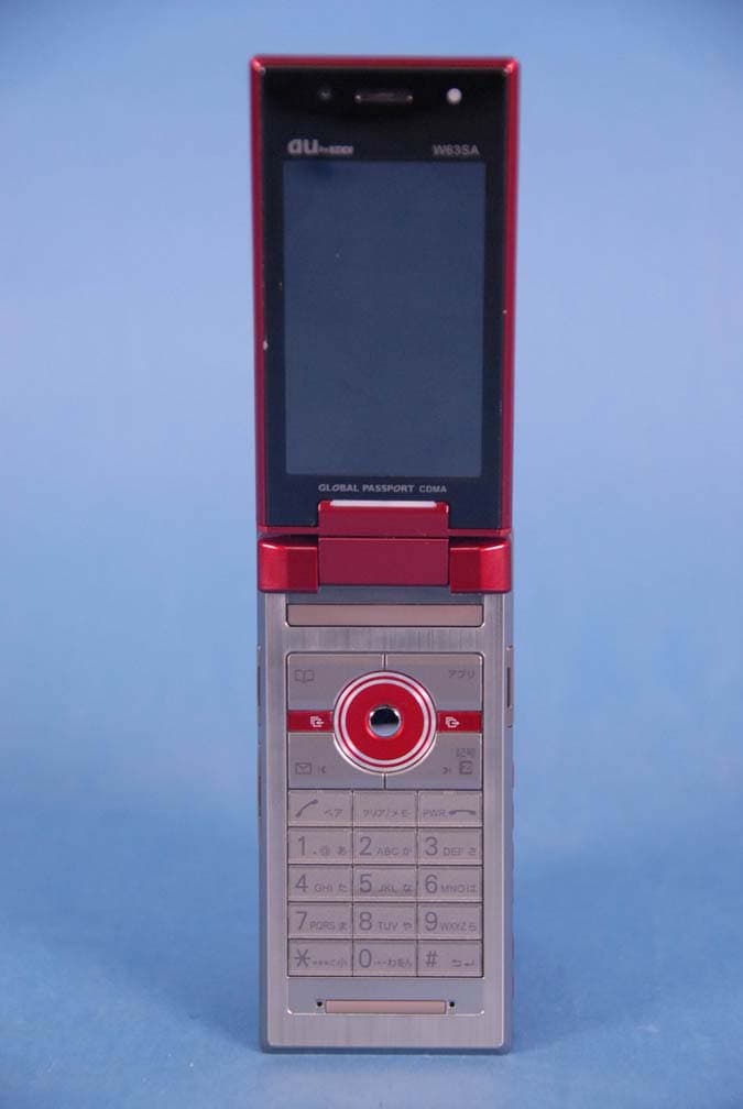
AEZW63SA
Mar 30, 2008Cellular CDMA Phone with Bluetooth
Equipment Class
TNE - Licensed Non-Broadcast Transmitter Held to Ear
AEZSCP-3800
Mar 09, 2008Cellular/ PCS CDMA Phone with Bluetooth
Equipment Class
JBP - Part 15 Class B Computing Device Peripheral
AEZSCP-25H
Sep 12, 2007Cellular/ PCS CDMA Phone with Bluetooth
Equipment Class
DSS - Part 15 Spread Spectrum Transmitter
AEZCPE-400-2C0
Jun 14, 2007W-CDMA subscriber terminal
Equipment Class
TNB - Licensed Non-Broadcast Station Transmitter
AEZNVM-4070
Jun 04, 2007PND (Personal Navigation Device)
Equipment Class
DXT - Part 15 Low Power Transceiver, Rx Verified