AEZPBS-CS37The Radio Cell Station for PHS WLL System
Sanyo Electric Co Ltd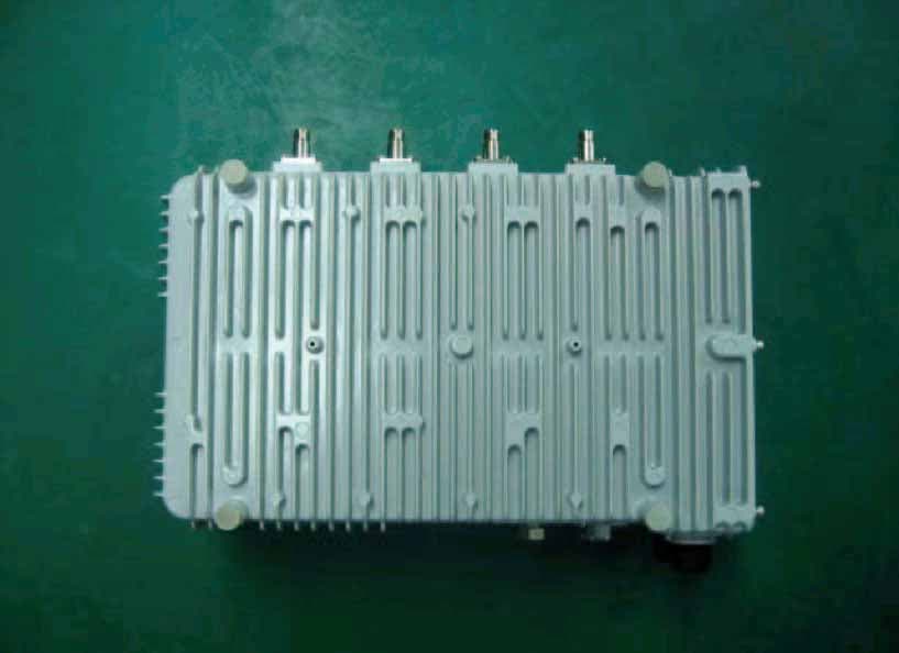
Click to zoom
Application Details
- Equipment Class
- PCB - PCS Licensed Transmitter
- Date of Grant
- Oct 14, 2003
- Application Purpose
- Original Equipment
- Date of Application
- Oct 14, 2003
- Equipment Note
- The Radio Cell Station for PHS WLL System
- Frequency Range
- 1880.15000000 - 1909.55000000
- Company
- Sanyo Electric Co Ltd
- Country
- United States
Documents & Files
Document Text
Text extracted from the exhibit documents filed with the FCC. Open a document above to read the original.
Users Manual
SANYO PHS Cell Station Sep 12, 2002 - User’s Manual - 1 Table of Contents Table of conten ts ............................................................................................................. ................ 1 Installation conditions ....................................................................................................... .......... 2,3 Fixing antenna for PBS-CS37 ................................................................................................... ..... 4 Condition of the antenna cable (PBS-CS37) ................................................................................ 5Terminal block appearance ..................................................................................................... ....... 6 Notes at the time of lid opening and closing ................................................................................. 7 Connection of the power cable ................................................................................................. ... 8,9 Connection of the lin e cable .................................................................................................. .. 11,12 Concerning the installation of cable .......................................................................................... .. 13 Warning ............ ........................................................................................................... .................. 14 Appendix (1), (2 ) ............................................................................................................. ......... 15,16 2 Installation conditions ] Place \ CS shall be installed in the place where the public can not easily access. \ Installation place shall have the structure which can support the weight of CSand its fixing facilities. \ Installation place shall be flat with no inclination. \ If CS is installed in the place where it may drop down, it shall be provided with protective measure against the drop. \ There shall be no object around 2m of CS. \ For the maintenance use, there shall be the space in about 500mm around thestand. \ CS shall be installed in the direction that the logo plate appears upwards. CScan be placed in vertical direction with arranging the fixing metal. 3 Installation conditions ] Antenna \ With fixing antennas, there shall be enough viewing angle from CS. (Targetangle: vertical: 30 degree or more, horizontal: 330 degree or more) ] ISDN Line \ Interconnection box for ISDN line shall be available near the CS. \ ISDN line length from the exchange to CS and its quality shall comply with the technical standard (ANSI T1.601-1992). ] Power supply \ AC120V shall be available with easy wiring connection work. 4 Fixing antenna for PBS-CS37 To ISDN Line AC120V MDFBreaker PBS-CS37 5 Connection of the antenna cable(PBS-CS37) ] Numbering arrangement \ Numbering arrangement of 1 - 4 shall be madeclockwise or counterclockwise. ] Tightening torque of the antenna cable:7 - 12 Kgf-cm. ] Wind the self-bonding tape between theantenna connector and the end of cable. 1 2 3 4 Upper side antenna 1 2 3 4 Upper sideantenna Case of Clockwise Case of Counterclockwise 6 Terminal block appearance(PBS-CS37) ] Terminal block of the power supply a nd line’s connections are shown below 1: Status indications LED Label2: Reset Switch3: Maintenance terminal connector4: Status indications LED5,10: Line check terminal connector6,9: Line terminal connector7,8: Line Status LED11: Power supply Terminal(N)12: GND Terminal(FG)13: Power supply Terminal(L)14: Earth clamp for Power cable15: Cable gland for power cable16: Cable gland for Line cable17: Earth clamp for Line cable18: GPS indications label for GPS model 7 Notes at the time oflid opening and closing ] Opening \ After loosening all lid’s fixation screws completely, pullupper part and central scre w of the lid, and slide. (Photo1) \ Confirm that all screws are free completely and two pins ofthe lid is at the right edge of two metal fittings ,therefore rotate the lid while pulling in the direction”an arrow” likebelow . (Photo2) ] Closing \ Tightening torque of Cap screw: 10 - 15 Kgf-cm \ Tighten with M4 hexagon Sock et Cap screws. (Cap screw). \ Tighten 6 screws equally and well balanced, after confirming that the waterproof packing is nonexistent between the lid and the CS. [Caution1] If the clamp face or waterproof packing is scarred by screw’s cusp, the waterp roof performance may not be obtained. [Caution 2] Photos of PBS-CS47 are used for explanations in this User’s Manual. (Photo1) (Photo2) 8 Connection of the power cable (1) 1) Reeve the cable from the cable gland nut into the lid. 2) Pull the cable out to enough length that the tip of the cable can be processed. 3) Peel the covering of the cable. (Photo 3)4) Peeling off core line.5) Loosen the copper shield and wind it onto the core wire’s tip 4 turns or more. (Photo3) Copper shield Covering end Covering 70 - 90mm interposition material: Cut it at the covering’ root. (figure) 8 - 9mm 60 - 80mm 15mm Copper shield *The cable color is generally used in Japan, and itused in U.S.A. shall comply with the local specifications. 9 Connection of the power cable (2) 6) Feazings processing of the core line. \ Push the upper part of the connector with afinger, and insert a core wire. (figure) \ L (Loading), N (Neutral), FG (Frame Ground). 7) Combine the copper shield to the position “FIX” of Photo 5. And tighten the cable gland firmly. \ [Caution] When the fixation of the terminal block’s lid is imperfect, it is feared that this CS gives hindrance to other electric devices. 8) Form core wires that are inserted into the power supply terminal. 9) The tightening of the dome nut must be done by hand without fail and tighten itstrongly. 10) Wind the self-bonding tape between the surface of dome nut a nd the end of cable. (figure) N:White FG:Red L:Black F i x Fo r m i n g (photo5) 10 Connection of the Line cable (1) 1) Reeve the cable from the dome nut into the …
Text truncated - open the document above for the full version.
Cover Letter(s)
From: Makoto Okada [[email protected]] Sent: Wednesday, September 24, 2003 7:51 PM To: [email protected] Cc: [email protected]; [email protected]; [email protected] Subject: Inquiry on your Question #6 Date: September 25, 2003 Assessment No. : AN03T3288 FCC ID: AEZPBS-CS37 Applicant: Sanyo Electric Co., Ltd. Attention: Mr. Steve Cheng EMC Engineering Manager Compliance Certification Services Reference: Your E-mail of 09/24/2003 Sending From: Makoto Okada EMC Div. Japan Quality Assurance Organization (JQA) KITA-KANSAI Testing Center Message: Thank you for your advice by your E-Mail of 09/24/2003. We have question about your Question #6. Question #6: Per FCC CFR 47 part 2 section 2.1033(c), please supply following documents: - The DC voltage and current supplied to final radio frequency amplifier. - Tune-up procedure over the power range, or at specific operating power level. Regard to the DC voltage and current supplied to final radio frequency amplifier is described on Page 1 of the previous submitted Operational / circuit description. (File named: Operational DESCRIPTION_PBS-CS37.pdf) Regard to the Tune-up procedure over the power range, or at specific operating power level is described on Page 5 of the previous submitted Operational / circuit description. (File named: Operational DESCRIPTION_PBS-CS37.pdf) Please confirm Page 1 and 5 in red character of the attached file. (File named: red marker.pdf) This file (File named: red marker.pdf) is same as the previous submitted Operational / circuit description. (File named: Operational DESCRIPTION_PBS-CS37.pdf) Are these descriptions correct ? Please give us your advice. If these are not what you request, please let us know as soon as possible. Your expedition of this application would be highly appreciated. Sincerely yours, (Ms.) Makoto Okada EMC Div. Japan Quality Assurance Organization (JQA) KITA-KANSAI Testing Center E-mail: [email protected]
Cover Letter(s)
From: Steve Cheng Sent: Wednesday, October 08, 2003 8:25 PM To: 'Makoto Okada' Cc: Scott Wang; Mike Kuo Subject: RE: Additional Information on Your Question (Assessment No. : AN03T3288) (1/5) Dear Makoto_san, Thanks for resending zip file, and I have no problem to unzip it this time, thanks for your help. Below are last two new questions I found today and hope you can address it ASAP, so that I can close up the review. 1. P 10 of the operational description stated that four 10dBi antennas are used to form a 4 elements adaptive array antenna and the result of this array antenna is expecting to generate 160W EIRP output. However, the included antenna pattern shown approximately 0 dBi peak gain. Please clarify if supplied antenna pattern is correct. 2. Does Antenna array intended be mounted at outdoor area only? what is the typical mounting height? 3. For your info, per FCC guideline the pi/4DQPSK-TDMA-NADC modulation will use DXW as emission designator but not G7W as what you have suggested. Best regards, Steve -----Original Message----- From: Makoto Okada [mailto:[email protected]] Sent: Wednesday, October 08, 2003 3:41 AM To: [email protected] Cc: [email protected]; [email protected] Subject: Additional Information on Your Question (Assessment No. : AN03T3288) (1/5) Date: October 8, 2003 Assessment No. : AN03T3288 FCC ID: AEZPBS-CS37 Applicant: Sanyo Electric Co., Ltd. Attention: Mr. Steve Cheng EMC Engineering Manager Compliance Certification Services Reference: Your E-mail of 10/08/2003 Sending From: Makoto Okada EMC Div. Japan Quality Assurance Organization (JQA) KITA-KANSAI Testing Center Message: Dear Mr. Steve Cheng: We are sorry to trouble you. Thank you for your advice by your E-mail of 10/08/2003. We resent the following files to you directly by our E-mail. (1/5) - (5/5) Internal photos (30 files) (We divide our attachments "Internal photos" into five times, and we send to you directly.) For your requested information, our response is as follows: Question #2 Please confirm each file "Internal Photo" (30 files). If these are not what you request, please let us know as soon as possible. Your expedition of this application would be highly appreciated. Sincerely yours, (Ms.) Makoto Okada EMC Div. Japan Quality Assurance Organization (JQA) KITA-KANSAI Testing Center E-mail: [email protected]
Cover Letter(s)
From: Makoto Okada [[email protected]] Sent: Saturday, October 11, 2003 11:39 PM To: [email protected] Cc: [email protected]; [email protected] Subject: Additional Information on Your Question (Assessment No. : AN03T3288) Date: October 12, 2003 Assessment No. : AN03T3288 FCC ID: AEZPBS-CS37 Applicant: Sanyo Electric Co., Ltd. Attention: Mr. Steve Cheng EMC Engineering Mananger Compliance Certification Services Reference: Your E-mail of 10/09/2003 Sending From: Makoto Okada EMC Div. Japan Quality Assurance Organization (JQA) KITA-KANSAI Testing Center Message: Dear Mr. Steve Cheng: Thank you for your advice by your E-mail of 10/09/2003. Per your request, we resent new exhibits to you directly by this E-mail. The attached files are as follows: Operational description (1 file) "CONFIDENTIAL" Test report (1 file) Please confirm each file. For your requested information, our responses are as follows: Question #1 We submitted the corrected Operational Description. Please refer to Page 11 "Antenna Pattern" of the corrected Operational Description. We added the description on Page 11 of the corrected Operational Description. Applicant's Answer: The level of this antenna pattern is relative comparison value, and not absolute value. Also, we stated as "dB", not "dBi". We stated as "0dB" as the reference of the maximum value of the data. Question #2 Applicant's Answer: It is intended to be mounted at outdoor area, and almost of all are mounted within 50 m in heights. Question #3 Applicant's Answer: There is no problem with us. Just because we use G7W in Japan, we described so. Would you please correct the Emission Designator from 286KG7W to 286KDXW on Application Form, Item "Emission Designator". By the change of this Emission Designator, we corrected Page 1 of Operational Description (Radio specifications, Item "Emission Designator") and Page 4 of Test Report (Description of the Equipment Under Test (EUT), 8)). Please treat Operational Description and Test Report submitted at this time as Opertional Description and Test Report. If these are not what you request, please let us know as soon as possible. Your expedition of this application would be highly appreciated. Sincerely yours, (Ms.) Makoto Okada EMC Div. Japan Quality Assurance Organization (JQA) KITA-KANSAI Testing Center E-mail: [email protected]
Cover Letter(s)
Question: Thanks for clarify the antenna gain. P 33 of test report indicates that measured maximum conducted power is 1.29W. However, the info provided in Product Spec and Operational Description does not match the measurement number. See analysis below DC voltage into final stage: 10.5V DC current into final amp stage: 1.2A DC power consumption in final stage: 12.6W RF output power per spec: 125mW x 4 = .5W (efficient 4%?) RF output power per measurement: 1.29W x 4 = 5.16W (efficient 41%) Please clarify the conflict between operational description and measurement data and make necessary change. To speed up the process, I am working on the grant condition now and will issue the grant on the same day when you clear the above document conflict. Answer: There is a description about the power in the section of EIRP in P10 of the operational/circuit description. We provide its description as below here. DC voltage into final stage: 10.5V DC current into final amp stage: 1.2A DC power consumption in final stage (total of 4 amps): 50.4W RF output power per spec: Average 125mW (peak 1W) x 4 = average 0.5W (peak 4W) (efficient 7.9%) RF output power per measurement: 1.29W x 4 = 5.16W (efficient 10.2%) There is a slight conflict between operational description and the measurement data, but it is not so big as 4% and 41%. Now we believe that there is no conflict in the documents.
Cover Letter(s)
TCB QA 092303-out.txt From:Steve Cheng Sent:Tuesday, September 23, 2003 10:11 PM To:'Makoto Okada' Cc:Scott Wang; Mike Kuo Subject:RE: Submission Documents for Assessment No. : AN03T3288 (2/2) Dear Makoto san, Sorry for the delay, please answer following question ASAP. Thanks. Best regards, Steve Cheng RT for project: AN03T3288 Notice_content Question #1: Page 14 of Users manual declared “This cell station has been tested and complies with the Federal Communications Commission (FCC) RF exposure limits for General Population/Uncontrolled exposure environment.” But no MPE calculation or other RF exposure measurement was performed to support this declaration. Please supply proper RF exposure evaluation data and specify a specific save-distance for end user to follow. Question #2: Both High and low Band edge measurements are required to demonstrate the compliance. However, only high edge, i.e. 1910M, was investigated. Please supply 1809M low bandedge measurement data too. Question #3: Per FCC CFR 47 part 24.238(a); conducted spur measurement shall use 1 MHz RBW or greater for out of band emissions, however, Page 3 of Conducted spur test data file used RBW=100k in 30M - 2G band measurement. Please correct. Question #4: Per FCC CFR 47 part 24.238(a); out of band emission shall lower than -13dBm. However, p25 of test report recorded 1.29W conducted output power and band edge spur is -35dBc, which means spur level at bandedge is -3.89dBm and is over the limit of -13dBm. Please clarify. Question #5: Please supply Antenna gain info for EIRP calculation. Question #6: Per FCC CFR 47 part 2 section 2.1033(c), please supply following documents: -The DC voltage and current supplied to final radio frequency amplifier. -Tune-up procedure over the power range, or at specific operating power level. Question #7: Internal photos are too blurry, please re-take or increase the resolution? The items indicated above must be submitted before processing can continue on the above referenced application. Failure to provide the requested information within 60 days of the original e-mail date may result in application dismissal and forfeiture of the filing fee. Also, please note that partial responses increase processing time and should not be submitted. Any questions about the content of this correspondence should be directed to the e-mail address listed below the name of the sender. Best Regards Steve Cheng Compliance Certification Services 561F Monterey Road Morgan Hill, CA 95037 Tel:(408)463-0885 x:119 Page 1 TCB QA 092303-out.txt Fax:(408)463-0888 [email protected] http:\\www.ccsemc.com Page 2
External Photos
2 Body: Back view
External Photos
3 Body: Bottom view
External Photos
1 Body: Front view
External Photos
7Body: Left-side view (Inside)
External Photos
6 Body: Left-side view
External Photos
4 Body: Right-side view
External Photos
5 Body: Top view
ID Label/Location Info
FCC ID LABEL
Internal Photos
27 Bottom case
Internal Photos
2 Control board (back)
Internal Photos
1 Control board (front)
Internal Photos
4 DSU (back)
Internal Photos
3 DSU (front)
Internal Photos
10 Front end module (back)
Internal Photos
9 Front end module (front)
Internal Photos
19 Front end module (Inner/front)
Internal Photos
11 Inside view Left: Processing board (top-half), DSU (under), Control board (under Processing board and DSU) Right (back of the front cover): Power unit (top-half)
Internal Photos
12 Inside view with processing board (left-half), DSU (right) and control board (under processing board and DSU)
Internal Photos
13 Inside view with control board
Internal Photos
14 Inside view with RFMB board (which is under the control board)
Internal Photos
15 Inside view with front end module (which is under the RFMB board)
Internal Photos
16 Inside view of the front cover with power unit (right), interface board (left-top), interface board for power (center), noise filter (left-bottom, left) and fan (left-bottom, right)
Internal Photos
17 Interface boards (back) for cascade and GPS Left:with GPS interface circuit Right:without GPS interface circuit
Internal Photos
18 Interface boards (front) for cascade and GPS Left:with GPS interface circuit Right:without GPS interface circuit
Internal Photos
24 Interface boards (back1) Surge protection circuits (with cover)
Internal Photos
25 Interface boards (back 2) Surge protection circuits (without cover)
Internal Photos
26 Interface boards (front) AC connector (right) Line connector (center) Login connector (left)
Internal Photos
20 LO module (Inner/back)
Internal Photos
21 LO module (Inner/front)
Internal Photos
29 Power unit (back)
Internal Photos
30 Power unit (front)
Internal Photos
6 Processing board (back)
Internal Photos
5 Processing board (front)
Internal Photos
8 RFMB board (back)
Internal Photos
7 RFMB board (front)
Internal Photos
28 RFMB board (TRM-LOM) (Inner) TR modules (two for each sides) LO module (center)
Internal Photos
22 TR module (Inner/back)
Internal Photos
23 TR module (Inner/front)
Parts List/Tune Up Info
Re: DC output at final amplifier stage Radio specifications Items Contents Note Frequency Range 1,880 - 1,910MHz carrier frequency 1,880.15 – 1909.85 MHz Carrier spacing 300kHz Emission Designator 288KG7W multiplex system multicarrier TDMA-TDD method Modulation p /4shiftQPSK Roll off factor is 0.5 Transmission rate 384kbps Radio channel composition 1C3T Receiver 4 circuits Receiving diversity method Adaptive array (4-array) Transmitter 4 circuit Transmitting diversity method Adaptive array (4-array) DC voltage of final amplifier +10.5V DC current of final amplifier 1.2A RF output power 5 – 125 mW at one antenna port Antenna port 4 ports TNC-K type connector Antenna impedance 50 ohm
Test Report
Page 1 of 22 Attachment A Occupied Bandwidth Measurement Test Date: September 14, 2003 Temp.: 23 ; Humi.: 60 %°C 1)Ant teminal : ANT1 CHTransmitting26dBData No.Frequency(MHz)BandwidthPage 2061880.150283 kHzPage 2 2551894.850282 kHzPage 3 491909.550283 kHzPage 4 2)Ant teminal : ANT2 CHTransmitting26dBData No.Frequency(MHz)BandwidthPage 2061880.150283 kHzPage 5 2551894.850284 kHzPage 6 491909.550283 kHzPage 7 3)Ant teminal : ANT3 CHTransmitting26dBData No.Frequency(MHz)BandwidthPage 2061880.150283 kHzPage 8 2551894.850284 kHzPage 9 491909.550282 kHzPage 10 4)Ant teminal : ANT4 CHTransmitting26dBData No.Frequency(MHz)BandwidthPage 2061880.150285 kHzPage 11 2551894.850286 kHzPage 12 491909.550284 kHzPage 13 .Note) The point shown on "" is the Maximum Point Tester : Shigeru Kinoshita JQA Application No.: KL80030382SRegulation : CFR 47 FCC Rules Part 24 Model No.: PBS-CS37Issue Date : October 6, 2003 FCC ID: AEZPBS-CS37 Page 2 of 22 Occupied Bandwidth Measurement Ant terminal: ANT 1 Transmitting Frequency : 1880.150 MHz (206 ch) JQA Application No.: KL80030382SRegulation : CFR 47 FCC Rules Part 24 Model No.: PBS-CS37Issue Date : October 6, 2003 FCC ID: AEZPBS-CS37 JQA Application No.: KL80030382SRegulation : CFR 47 FCC Rules Part 24 Model No.: PBS-CS37Issue Date : October 6, 2003 FCC ID: AEZPBS-CS37 Page 3 of 22 Occupied Bandwidth Measurement Ant terminal: ANT 1 Transmitting Frequency : 1894.850 MHz (255 ch) JQA Application No.: KL80030382SRegulation : CFR 47 FCC Rules Part 24 Model No.: PBS-CS37Issue Date : October 6, 2003 FCC ID: AEZPBS-CS37 Page 4 of 22 Occupied Bandwidth Measurement Ant terminal: ANT 1 Transmitting Frequency : 1909.550 MHz (49 ch) JQA Application No.: KL80030382SRegulation : CFR 47 FCC Rules Part 24 Model No.: PBS-CS37Issue Date : October 6, 2003 FCC ID: AEZPBS-CS37 Page 5 of 22 Occupied Bandwidth Measurement Ant terminal: ANT 2 Transmitting Frequency : 1880.150 MHz (206 ch) JQA Application No.: KL80030382SRegulation : CFR 47 FCC Rules Part 24 Model No.: PBS-CS37Issue Date : October 6, 2003 FCC ID: AEZPBS-CS37 Page 6 of 22 Occupied Bandwidth Measurement Ant terminal: ANT 2 Transmitting Frequency : 1894.850 MHz (255 ch) JQA Application No.: KL80030382SRegulation : CFR 47 FCC Rules Part 24 Model No.: PBS-CS37Issue Date : October 6, 2003 FCC ID: AEZPBS-CS37 Page 7 of 22 Occupied Bandwidth Measurement Ant terminal: ANT 2 Transmitting Frequency : 1909.550 MHz (49 ch) JQA Application No.: KL80030382SRegulation : CFR 47 FCC Rules Part 24 Model No.: PBS-CS37Issue Date : October 6, 2003 FCC ID: AEZPBS-CS37 Page 8 of 22 Occupied Bandwidth Measurement Ant terminal: ANT 3 Transmitting Frequency : 1880.150 MHz (206 ch) JQA Application No.: KL80030382SRegulation : CFR 47 FCC Rules Part 24 Model No.: PBS-CS37Issue Date : October 6, 2003 FCC ID: AEZPBS-CS37 Page 9 of 22 Occupied Bandwidth Measurement Ant terminal: ANT 3 Transmitting Frequency : 1894.850 MHz (255 ch) JQA Application No.: KL80030382SRegulation : CFR 47 FCC Rules Part 24 Model No.: PBS-CS37Issue Date : October 6, 2003 FCC ID: AEZPBS-CS37 Page 10 of 22 Occupied Bandwidth Measurement Ant terminal: ANT 3 Transmitting Frequency : 1909.550 MHz (49 ch) JQA Application No.: KL80030382SRegulation : CFR 47 FCC Rules Part 24 Model No.: PBS-CS37Issue Date : October 6, 2003 FCC ID: AEZPBS-CS37 Page 11 of 22 Occupied Bandwidth Measurement Ant terminal: ANT 4 Transmitting Frequency : 1880.150 MHz (206 ch) JQA Application No.: KL80030382SRegulation : CFR 47 FCC Rules Part 24 Model No.: PBS-CS37Issue Date : October 6, 2003 FCC ID: AEZPBS-CS37 Page 12 of 22 Occupied Bandwidth Measurement Ant terminal: ANT 4 Transmitting Frequency : 1894.850 MHz (255 ch) JQA Application No.: KL80030382SRegulation : CFR 47 FCC Rules Part 24 Model No.: PBS-CS37Issue Date : October 6, 2003 FCC ID: AEZPBS-CS37 Page 13 of 22 Occupied Bandwidth Measurement Ant terminal: ANT 4 Transmitting Frequency : 1909.550 MHz (49 ch) JQA Application No.: KL80030382SRegulation : CFR 47 FCC Rules Part 24 Model No.: PBS-CS37Issue Date : October 6, 2003 FCC ID: AEZPBS-CS37 Page 14 of 22 Band-Edge Emission Measurement Test Date: September 14, 2003 Temp.: 23 ; Humi.: 60 %°C 1) Low Band-Edge Measurement Ant terinalTransmittingBand-Edge Band-EdgeData Frequency(MHz)Frequency(MHz) Level[dBc]Page ANT 11880.1501870.000-84.7Page 15 ANT 21880.1501870.000-80.4Page 16 ANT 31880.1501870.000-82.7Page 17 ANT 41880.1501870.000-82.5Page 18 2) High Band-Edge Measurement Ant terinalTransmittingBand-Edge Band-EdgeData Frequency(MHz)Frequency(MHz) Level[dBc]Page ANT 11909.5501910.000-70.5Page 19 ANT 21909.5501910.000-67.5Page 20 ANT 31909.5501910.000-67.5Page 21 ANT 41909.5501910.000-71.0Page 22 .Note) The point shown on "" is the Maximum Point Tester : Shigeru Kinoshita JQA Application No.: KL80030382SRegulation : CFR 47 FCC Rules Part 24 Model No.: PBS-CS37Issue Date : October 6, 2003 FCC ID: AEZPBS-CS37 Page 15 of 22 Band-Edge Emissiom Measurement Ant terminal: ANT 1 Transmitting Frequency : 1880.150 MHz (206 ch) Band-Edge Frequency: 1870.000 MHz JQA Application No.: KL80030382SRegulation : CFR 47 FCC Rules Part 24 Model No.: PBS-CS37Issue Date : October 6, 2003 FCC ID: AEZPBS-CS37 Page 16 of 22 Band-Edge Emissiom Measurement Ant terminal: ANT 2 Transmitting Frequency : 1880.150 MHz (206 ch) Band-Edge Frequency: 1870.000 MHz JQA Application No.: KL80030382SRegulation : CFR 47 FCC Rules Part 24 Model No.: PBS-CS37Issue Date : October 6, 2003 FCC ID: AEZPBS-CS37 Page 17 of 22 Band-Edge Emissiom Measurement Ant terminal: ANT 3 Transmitting Frequency : 1880.150 MHz (206 ch) Band-Edge Frequency: 1870.000 MHz JQA Application No.: KL80030382SRegulation : CFR 47 FCC Rules Part 24 Model No.: PBS-CS37Issue Date : October 6, 2003 FCC ID: AEZPBS-CS37 Page 18 of 22 Band-Edge Emissiom Measurement Ant terminal: ANT 4 Transmitting Frequency : 1880.150 MHz (206 ch) Band-Edge Frequency: 1870.000 MHz JQA Application No.: KL80030382SRegulation : CFR 47 FCC Rules Part 24 Model No.: PBS-CS37Issue Date : October 6, 2003 F…
Text truncated - open the document above for the full version.
Test Report
Page 1 of 38 Attachment B Antenna Conducted Spurious Emission Measurement (§2.1051,§24.238)) -Spurious Emission Except the harmonics frequency- Test Procedure : The Antenna Conducted Emission was measured with a spectrum analyzer. The test system is shown as follows: 1) Frequency Range : 9kHz - 2.0GHz EUT10 dBSpectrumAntenna Att.AnalyzerTerminal 2) Frequency Range : 2.0GHz - 5.8GHz EUTHigh Pass10 dBSpectrumAntenna FilterAttenuatorAnalyzerTerminal 3) Frequency Range : 5.8GHz - 20GHz EUTHighPass10dBPre-10dBSpectrumAntenna FilterAtt.Amp.Att.AnalyzerTerminal Antenna Conducted Spurious Emission Measurement Test location : KITA-KANSAI Testing Center 7-7, Ishimaru, 1-Chome, Mino-Shi, Osaka, 562-0027, Japan -Shieldedroomz KAMEOKA EMC Branch 9-1, Ozaki, Inukanno, Nishibetsuin-Cho, Kameoka-Shi, Kyoto, 621-0126, Japan -Shieldedroom{ Used test instruments: Model No.Device IDLast Cal. DateCal. Interval - MP721CD - 66{ - 4T-10D - 73May, 20031 Yearz - 4T-10D - 74May, 20031 Yearz -2-10D-40July,20031Yearz -2-10D-79{ -2-10D-80{ - UHP-127D - 42May, 20031 Yearz - UHP-128D - 43{ - 8566BA - 13February, 20031 Yearz - 8593AA - 15{ - DBL-0618N515A - 33May, 20031 Yearz - MZ5010CD - 81November, 20021 Yearz - 8673DB - 2April, 20031 Yearz - CableC - 40 - 9June, 20031 Yearz - CableC - 40 - 11May, 20031 Yearz - CableC - 40 - 12May, 20031 Yearz Environmental conditions: Temperature: 23 °C Humidity: 60 % JQA Application No.: KL80030382SRegulation : CFR 47 FCC Rules Part 24 Model No.: PBS-CS37Issue Date : October 6, 2003 FCC ID: AEZPBS-CS37 Page 2 of 38 Measurment Result: Theplotdataisshownintheattachment. Pages 3-11 : ANT 1 Pages 12-20 : ANT 2 Pages 21-29 : ANT 3 Pages 30-38 : ANT 4 The all spurious emission not listed in pages 35-39 of 50 in KL8030382 were found to be more than 20 dB below the limit. Sample Calculation: Note: The Amp Gain , the attenuator loss and the cable loss are included in the correction factor. Judgement procedure: The sprious data is compared to the antenna conduced emisson level of the discrete frequcies of pages 35-39 of 62. Transmitting Frequency :1880.150 MHz at ANT1 FrequencyCorrectio nLimits Factor [MHz][dB](dBm) 3760.300 11.7 -53.6 -13.0 -41.9 5640.450 11.7 < -62.0 -13.0 <-50.3 7520.600 -16.8 -51.4 -13.0 -68.2 9400.750 -16.7 -51.4 -13.0 -68.1 15041.200 -16.1 < -60.0 -13.0 <-76.1 (dBm) Meter ReadingsResults (dBm) JQA Application No.: KL80030382SRegulation : CFR 47 FCC Rules Part 24 Model No.: PBS-CS37Issue Date : October 6, 2003 FCC ID: AEZPBS-CS37 JQA Application No.: KL80030382SRegulation : CFR 47 FCC Rules Part 24 Model No.: PBS-CS37Issue Date : October 6, 2003 FCC ID: AEZPBS-CS37 Page 3 of 38 Antenna Conducted Spurious Emission Measurement Ant terminal: ANT 1 Transmitting Frequency: 1880.150 MHz (206 ch) Frequency Range: 9kHz - 30 MHz Antenna Conducted Spurious Emission Measurement Ant terminal: ANT 1 Transmitting Frequency: 1880.150 MHz (206 ch) Frequency Range: 30MHz - 2GHz JQA Application No.: KL80030382SRegulation : CFR 47 FCC Rules Part 24 Model No.: PBS-CS37Issue Date : October 6, 2003 FCC ID: AEZPBS-CS37 Page 4 of 38 Antenna Conducted Spurious Emission Measurement Ant terminal: ANT 1 Transmitting Frequency: 1880.150 MHz (206 ch) Frequency Range: 2GHz - 5.8GHz Antenna Conducted Spurious Emission Measurement Ant terminal: ANT 1 Transmitting Frequency: 1880.150 MHz (206 ch) Frequency Range: 5.8GHz - 12.55GHz JQA Application No.: KL80030382SRegulation : CFR 47 FCC Rules Part 24 Model No.: PBS-CS37Issue Date : October 6, 2003 FCC ID: AEZPBS-CS37 Page 5 of 38 Antenna Conducted Spurious Emission Measurement Ant terminal: ANT 1 Transmitting Frequency: 1880.150 MHz (206 ch) Frequency Range: 12.55GHz - 20GHz JQA Application No.: KL80030382SRegulation : CFR 47 FCC Rules Part 24 Model No.: PBS-CS37Issue Date : October 6, 2003 FCC ID: AEZPBS-CS37 Page 6 of 38 Antenna Conducted Spurious Emission Measurement Ant terminal: ANT 1 Transmitting Frequency: 1894.850 MHz (255 ch) Frequency Range: 9kHz - 30 MHz Antenna Conducted Spurious Emission Measurement Ant terminal: ANT 1 Transmitting Frequency: 1894.850 MHz (255 ch) Frequency Range: 30MHz - 2GHz JQA Application No.: KL80030382SRegulation : CFR 47 FCC Rules Part 24 Model No.: PBS-CS37Issue Date : October 6, 2003 FCC ID: AEZPBS-CS37 Page 7 of 38 Antenna Conducted Spurious Emission Measurement Ant terminal: ANT 1 Transmitting Frequency: 1894.850 MHz (255 ch) Frequency Range: 2GHz - 5.8GHz Antenna Conducted Spurious Emission Measurement Ant terminal: ANT 1 Transmitting Frequency: 1894.850 MHz (255 ch) Frequency Range: 5.8GHz - 12.55GHz JQA Application No.: KL80030382SRegulation : CFR 47 FCC Rules Part 24 Model No.: PBS-CS37Issue Date : October 6, 2003 FCC ID: AEZPBS-CS37 Page 8 of 38 Antenna Conducted Spurious Emission Measurement Ant terminal: ANT 1 Transmitting Frequency: 1894.850 MHz (255 ch) Frequency Range: 12.55GHz - 20GHz JQA Application No.: KL80030382SRegulation : CFR 47 FCC Rules Part 24 Model No.: PBS-CS37Issue Date : October 6, 2003 FCC I…
Text truncated - open the document above for the full version.
Contact Information
Applicant
Hideaki Mukaida
Test Firm
Japan Quality Assurance Org.Katsumi Nishii
Technical Specifications
| # | Rule Parts | Frequency Range | Power Output | Emission | Tolerance |
|---|---|---|---|---|---|
| 1 | 24E | 1.88 GHz - 1.91 GHz | 5.08 W | 286KDXW | 2.5000000000 ppm |
Other Applications from Sanyo Electric Co Ltd
AEZW63SA
Mar 30, 2008Cellular CDMA Phone with Bluetooth
Equipment Class
TNE - Licensed Non-Broadcast Transmitter Held to Ear
AEZSCP-3800
Mar 09, 2008Cellular/ PCS CDMA Phone with Bluetooth
Equipment Class
JBP - Part 15 Class B Computing Device Peripheral
AEZSCP-25H
Sep 12, 2007Cellular/ PCS CDMA Phone with Bluetooth
Equipment Class
DSS - Part 15 Spread Spectrum Transmitter
AEZCPE-400-2C0
Jun 14, 2007W-CDMA subscriber terminal
Equipment Class
TNB - Licensed Non-Broadcast Station Transmitter
AEZNVM-4070
Jun 04, 2007PND (Personal Navigation Device)
Equipment Class
DXT - Part 15 Low Power Transceiver, Rx Verified