AEZPBS-CS47The Radio Cell Station for PHS WLL System
Sanyo Electric Co Ltd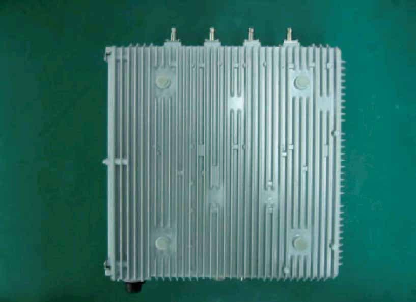
Click to zoom
Application Details
- Equipment Class
- PCB - PCS Licensed Transmitter
- Date of Grant
- Nov 02, 2003
- Application Purpose
- Original Equipment
- Date of Application
- Nov 02, 2003
- Equipment Note
- The Radio Cell Station for PHS WLL System
- Frequency Range
- 1880.15000000 - 1909.55000000
- Company
- Sanyo Electric Co Ltd
- Country
- United States
Documents & Files
Document Text
Text extracted from the exhibit documents filed with the FCC. Open a document above to read the original.
Users Manual
SANYO PHS Cell Station Sep 12, 2002 - User’s Manual - 1 Table of Contents Table of contents ........................................ ..................................................................... ................ 1 Installation conditions ....................................................................................................... .......... 2,3 Fixing antenna for PBS-CS47 ................................................................................................... .. 4,5 Condition of the antenna cable (PBS -CS47) ................................................................................ 6 Terminal block appearance ..................................................................................................... ....... 7 Notes at the time of lid opening and closing ................................................................................. 8 Connection of the power cable ................................................................................................. . 9,10 Connection of the line cabl e .................................................................................................. .. 11-13 Concerning the installation of cable .......................................................................................... .. 14 Warning ............................................................................ ........................................... .................. 15 Appendix (1), (2) ............................................................. ................................................ ......... 16,17 2 Installation conditions ] Place \ CS shall be installed in the place where the public can not easily access. \ Installation place shall have the structure which can support the weight of CSand its fixing facilities. \ Installation place shall be flat with no inclination. \ If CS is installed in the place where it may drop down, it shall be provided with protective measure against the drop. \ There shall be no object around 2m of CS. \ For the maintenance use, there shall be the space in about 500mm around thestand. \ CS shall be installed in the direction that the logo plate appears upwards. CScan be placed in vertical direction with arranging the fixing metal. 3 Installation conditions ] Antenna \ With fixing antennas, there shall be enough viewing angle from CS. (Targetangle: vertical: 30 degree or more, horizontal: 330 degree or more) ] ISDN Line \ Interconnection box for ISDN line shall be available near the CS. \ ISDN line length from the exchange to CS and its quality shall comply with the technical standard (ANSI T1.601-1992). ] Power supply \ AC120V shall be available with easy wiring connection work. 4 Fixing antenna for PBS-CS47 (case 1) To ISDN Line AC120V MDFBreaker ] In case of vertical separate distance betweenantennas: 15cm or more Angle between arms : 0 degree Vertical separate distance between antennas Angle between arms:0 degree Top view 5 Fixing antenna for PBS-CS47 (case 2) ] In case of vertical separate distance betweenantennas: less than 15cm Angle between arms : 45 degreeHorizontal separate distance between antennas: 40cm or more . Angle between arms:45 degree Top view Horizontal separate distance > 40cm To ISDN Line AC120V MDFBreaker * If horizontal separate distance is le ss than 40cm,the perfo rmance is reduced 6 Connection of the antenna cable(PBS-CS47) ] Order of cable connection \ Antenna connector 1 - 4 : upper side \ Antenna connector 5 - 8 : lower side ] Numbering arrangement \ Numbering arrangement of 1 - 4 and 5 - 8shall be made clockwise orcounterclockwise. ] Tightening torque of the antenna cable:7 - 12 Kgf-cm. ] Wind the self-bonding tape between theantenna connector and the end of cable. 1 2 3 4 Upper side antenna 5 6 7 8 Lower sideantenna 1 2 3 4 5 6 7 8 Upper sideantenna Lower sideantenna Case of Clockwise(Case1)Case of Counterclockwise(Case2) 7 Terminal block appearance(PBS-CS47) ] Terminal block of the power supply a nd line’s connections are shown below 1:Cable gland for power cable2:Cable gland for Line cable3:Earth clamp for Power cable4:Power supply Terminal(L)5:GND Terminal(FG)6:Power supply Terminal(N)7:Earth clamp for Line cable8,13,14,19:Line chec k terminal connector 9,11,16,17:Line Status LED 10,12,15,18:Line terminal connector20:Status indications LED21:Maintenance terminal connector22:Reset Switch23:Status indica tions LED Label 24:GPS indications label for GPS model 8 Notes at the time oflid opening and closing ] Opening \ After loosening all lid’s fixation screws completely, pullupper part and central scre w of the lid, and slide. (Photo1) \ Confirm that all screws are free completely and two pins ofthe lid is at the right edge of two metal fittings ,therefore rotate the lid while pulling in the direction”an arrow” likebelow . (Photo2) ] Closing \ Tightening torque of Cap screw: 10 - 15 Kgf-cm \ Tighten with M4 hexagon Sock et Cap screws. (Cap screw). \ Tighten 6 screws equally and well balanced, after confirming that the waterproof packing is nonexistent between the lid and the CS. [Caution] If the clamp face or waterp roof packing is scarred by screw’s cusp, the waterproof performance may not beobtained (Photo1) (Photo2) 9 Connection of the power cable (1) 1) Reeve the cable from the cable gland nut into the lid. 2) Pull the cable out to enough length that the tip of the cable can be processed. 3) Peel the covering of the cable. (Photo 3)4) Peeling off core line.5) Loosen the copper shield and wind it onto the core wire’s tip 4 turns or more. (Photo3) Copper shield Covering end Covering 70 - 90mm interposition material: Cut it at the covering’ root. (figure) 8 - 9mm 60 - 80mm 15mm Copper shield *The cable color is generally used in Japan, and itused in U.S.A. shall comply with the local specifications. 10 Connection of the power cable (2) 6) Feazings processing of the core line. \ Push the upper part of the connector with afinger, and insert a core wire. (figure) …
Text truncated - open the document above for the full version.
Cover Letter(s)
O PERATIONAL /C IRCUIT D ESCRIPTION Appearance/form Item Specification Note Dimensions 370W x 400D x 210H(mm) Not including protrusion things Capacity 31.1 litters Weight 17.7kg Material Aluminum die casting Color Pantone 422c Holes for hanging ¢6(mm) x 2 For construction work Screw hole M10 (depth 10mm Min.) x 8 Radio specifications Items Contents Note Frequency Range 1,880 - 1,910MHz carrier frequency 1,880.15 – 1909.55 MHz Carrier spacing 300kHz Emission Designator 286KDXW multiplex system multicarrier TDMA-TDD method Modulation π/4shiftQPSK Roll off factor is 0.5 Transmission rate 384kbps Radio channel composition 1C7T Receiver 8 circuits Receiving diversity method Adaptive array (4-array x 2) Transmitter 8 circuit Transmitting diversity method Adaptive array (4-array x 2) DC voltage of final amplifier +10.5V DC current of final amplifier 1.2A RF output power 5 – 125 mW at one antenna port typical mounting height within 50m Antenna port 8 ports TNC-K type connector Antenna impedance 50 ohm Line specifications Items Contents Note Line Interface I’I/F ANSI T1.601-1992 Line capacity 4 line(2B+D, 2B, 2B, 2B) Pin header 232D-04P1B2-S15A Wire jacket outsize diameter 5 to 10¢(mm) Cascade interface connection specifications(Option) Item Specifications Note Interface Original Enclosure side connector HR22-12WTRA-20PC
Cover Letter(s)
TABLE OF CONTENTS ATTACHMENT A:CONFIDENTIAL LETTER ATTACHMENT B:AUTHORIZATION LETTER ATTACHMENT C:TEST REPORT ATTACHMENT D:FCC ID LABEL / LOCATION ATTACHMENT E:EXTERNAL PHOTOGRAPHS ATTACHMENT F:INTERNAL PHOTOGRAPHS ATTACHMENT G:BLOCK DIAGRAMS ATTACHMENT H:SCHEMATIC DIAGRAMS ATTACHMENT I:PARTS LIST ATTACHMENT J:OPERATIONAL / CIRCUIT DESCRIPTION ATTACHMENT K:USER’S MANUAL
Cover Letter(s)
Question #1: Please clarify if both antenna pair (Group antenna 1-4 and Group antenna 5-8) could transmit the signal simultaneously or only one group at a time? Answer: Those two antenna pairs can transmit different signals simultaneously. Since TDMA/TDD system is used, those pairs’ timing are synchronized. Question #2: What is the purpose of add one more set of adaptive antenna to existing CS and what is the typical relative installation position for two 4-element adaptive arrays? Is it be designed to be cascaded as shown on p 4-5 of Users annual to form an new adaptive array or it is intended to be installed in a different location to take care of different cell area or to form two separate scanning beams? Answers: The purpose of adding one more set of adaptive antenna to existing CS is to increase the number of users who can connect to one CS. To equip this type of CS in urban area where many users gather is better in terms of dealing with high traffic, decreasing installation sites and so on. For typical relative installation position for two 4-element adaptive arrays, please find attached picture. Two different adaptive arrays are equipped to enable CS to handle two users at same time. Question #2: P8 of "Block_PBS-CS47_030929.pdf" RF input shall be RF output. Please correct. Answer: We have changed as above. Question #3: Is GPS circuit receiving only? Answer: GPS circuit does not have transmitting function for RF signals. But it transmits and receives controlling signals. Question #1: P15 of user manual stated: This cell station has been tested and complies with the Federal Communications Commission (FCC) RF exposure limits for General Population/Uncontrolled exposure environment. The design of this cell station complies with the FCC guidelines and these international standards. This cell station complies with the MPE requirements by providing a minimum save-distance between the antenna and any persons. Please keep the minimum save-distance of 1.17 meters from the cell station. Normally, RF exposure for licensed base station is addressed during the site installation, but not in product certification. So please delete this info from the users manual. But do include necessary RF exposure installation instruction for installer and end user to follow. Like: ............ To satisfy the FCC RF exposure requirement, a minimum separation distance of x-feet (the safety distance which you obtain from MPE calculation) must be maintained between the nearby person and radiating elements........................... Answer: Warning in the user’s manual has changed as following. WARNING RF exposure installation instruction To satisfy the FCC RF exposure requirement, a minimum separation distance of 4 feet must be maintained between the nearby person and radiating elements. Unauthorized alteration, modifications or attachments could impair its quality, damage the cell station, or result in violation of FCC regulations. Review will continue when above issues are clarified. Please continue the review as we believe those are clarified now.
Cover Letter(s)
Understand this is an urging project and we will do our best to expedite the process. According to the info you supplied in the last email, I have more questions for you. Please clarify them ASAP, Thanks. Question #6: Since two antennas array will be used in very close proximity to each other, especially when both are seated at same center with 45 degree offset. Please verify that the two antennas in 45 degree offset position will not generate more unwanted emission or increase the antenna gain in comparing to the tested single antenna array configuration. Answer: For this cell station, two systems are in one chassis, but each system is operated separately. Since each system is operated at different frequency, it does not increase the antenna gain compared to cell station with one system. (It could happen only when the frequencies are same by chance, although there is little possibility for that.) We think you might care about the TX intermodulation regarding to unwanted emission, but the cell station has 2 stages of isolators behind power amplifier to take sufficient care of the problem. Question #7: What is the highest EIRP power when both antenna main lobes was directed to the same spot at all possible combinations. A higher output power is expected, since two adaptive arrays can transmit the signal simultaneously to target two different users and they could be in the same spot. Answer: Two RF systems operate in this cell station separately, and it is same as that there are two cell stations of one RF system for each. We believe EIRP power at each RF system does not change since this cell station is operated at another frequency. Thank you for your cooperation.
Cover Letter(s)
Q6, my original concern is that the antenna pattern or gain could be changed when a secondary adaptive array is introduced to the near field region of the original antenna array. Could you please verify this? Answer: There is a problem that the adaptive array system does not work with accuracy when the signal that is input into DSP is distorted. The signal is distorted and the calculation of array becomes inaccuracy, when each of RF system is brought near another. However, there is no problem by the restriction of separating those more than 40cm when operating. Q7, On the grant, the power indicated will be total power of whole system but not partial of the system, so please supply total output power info. If antenna pattern does not change significantly after the introduction of the second antenna, then the usage of calculation method to sum up both output is acceptable. Answer: There is no affecting of the second array as said in Q7 because PHS has self-sustaining carrier sense with personal station and cell station each, so it selects the frequency that is not in use and with no such affection. Therefore, the sum of both outputs is the total output power. Example: 255CH: 171.40+154.88=326.88[W]
External Photos
2Body: Back view
External Photos
1 Body: Front view
External Photos
4Body: Left-side view
External Photos
7 Body: Right-side view (Inside)
External Photos
5 Body: Top view
External Photos
3Body: Bottom view
External Photos
6 Body: Right-side view
External Photos
9 Front end module (front)
ID Label/Location Info
FCC ID LABEL
Internal Photos
29 Bottom case
Internal Photos
2 Control board (back)
Internal Photos
1 Control board (front)
Internal Photos
4 DSU (back)
Internal Photos
3 DSU (front)
Internal Photos
10 Front end module (back)
Internal Photos
21 Front end module (Inner/front)
Internal Photos
11 Inside view Left: Processing board (top-half, right), DSU (top-half, left), control board (under Processing board and DSU), 2 fans (center), interface board for cascade and GPS (bottom, left), noise filter (bottom, right), interface board for power (between right-side fan and noise filter) Right (back of the front cover): RFMB board and front end module (top- half), power unit (bottom)
Internal Photos
12 Inside view with processing board (right-bottom), DSU (right-top) and control board (under processing board and DSU), 2 fans (center), interface board for cascade and GPS (left-top), interface board for power (bottom, next to lower-fan), noise filter (bottom-left)
Internal Photos
13 Inside view with control board (top-half), 2 fans (center), interface board for cascade and GPS (bottom-left), interface board for power (between right-fan and noise filter), noise filter (bottom-right)
Internal Photos
14Inside view with RFMB board (which is under control board), 2 fans (center), interface board for cascade and GPS (bottom-left), interface board for power (between right-fan and noise filter), noise filter (bottom-right)
Internal Photos
15 Inside view with front end modules (which are under RFMB board), 2 fans (center), interface board for cascade and GPS (bottom-left), interface board for power (between right-fan and noise filter), noise filter (bottom-right)
Internal Photos
16 Inside view (back of the front cover) with RFMB board and front end modules (top-half), and power unit (bottom-half)
Internal Photos
17Inside view (back of the front cover) with RFMB board (top-half, without cover), and power unit (bottom- half)
Internal Photos
18Inside view (back of the front cover) with front end modules (top-half, which are under RFMB board), and power unit (bottom-half)
Internal Photos
19 Interface board for cascade and GPS (back) with GPS interface circuit (left) without GPS interface circuit (right)
Internal Photos
20Interface board for cascade and GPS (front) with GPS interface circuit (left) without GPS interface circuit (right)
Internal Photos
26 Interface boards (back1) Surge protection circuits (with cover)
Internal Photos
27 Interface boards (back2) Surge protection circuits (without cover)
Internal Photos
28 Interface boards (front) AC connector (left) Line connector (center) Login connector (right)
Internal Photos
22 LO module (Inner/back)
Internal Photos
23 LO module (Inner/front)
Internal Photos
31 Power unit (Inner/back)
Internal Photos
32 Power unit (Inner/front)
Internal Photos
6 Processing board (back)
Internal Photos
5 Processing board (front)
Internal Photos
8 RFMB board (back)
Internal Photos
7 RFMB board (front)
Internal Photos
30 RFMB board (TRM-LOM) (Inner) TR modules (two for each sides) LO modules (center)
Internal Photos
24 TR module (Inner/back)
Internal Photos
25 TR module (Inner/front)
Test Report
JQA Application No.: KL80030385Regulation : CFR 47 FCC Rules Part 24 Model No.: PBS-CS47Issue Date : October 6, 2003 FCC ID: AEZPBS-CS47 Page 27 of 43 Band-Edge Emission Measurement Test Date: September 21, 2003 Temp.: 24 ; Humi.: 60 %°C 1)Low Band-Edge Measurement Ant terinalTransmittingBand-Edge Band-EdgeData Frequency(MHz)Frequency(MHz) Level[dBc]Page ANT 11880.1501870.000-81.1Page 28 ANT 21880.1501870.000-82.3Page 29 ANT 31880.1501870.000-80.5Page 30 ANT 41880.1501870.000-80.9Page 31 ANT 51880.1501870.000-83.6Page 32 ANT 61880.1501870.000-82.6Page 33 ANT 71880.1501870.000-82.4Page 34 ANT 81880.1501870.000-81.3Page 35 2)High Band-Edge Measurement Ant terinalTransmittingBand-Edge Band-EdgeData Frequency(MHz)Frequency(MHz) Level[dBc]Page ANT 11909.8501910.000-67.9Page 36 ANT 21909.8501910.000-63.6Page 37 ANT 31909.8501910.000-66.9Page 38 ANT 41909.8501910.000-67.2Page 39 ANT 51909.8501910.000-64.3Page 40 ANT 61909.8501910.000-64.3Page 41 ANT 71909.8501910.000-64.9Page 42 ANT 81909.8501910.000-64.6Page 43 .Note) The point shown on "" is the Maximum Point Tester : Shigeru Kinoshita JQA Application No.: KL80030385Regulation : CFR 47 FCC Rules Part 24 Model No.: PBS-CS47Issue Date : October 6, 2003 FCC ID: AEZPBS-CS47 Page 28 of 43 Band-Edge Emissiom Measurement Ant terminal: ANT 1 Transmitting Frequency : 1880.150 MHz (206 ch) Band-Edge Frequency: 1870.000 MHz JQA Application No.: KL80030385Regulation : CFR 47 FCC Rules Part 24 Model No.: PBS-CS47Issue Date : October 6, 2003 FCC ID: AEZPBS-CS47 Page 29 of 43 Band-Edge Emissiom Measurement Ant terminal: ANT 2 Transmitting Frequency : 1880.150 MHz (206 ch) Band-Edge Frequency: 1870.000 MHz JQA Application No.: KL80030385Regulation : CFR 47 FCC Rules Part 24 Model No.: PBS-CS47Issue Date : October 6, 2003 FCC ID: AEZPBS-CS47 Page 30 of 43 Band-Edge Emissiom Measurement Ant terminal: ANT 3 Transmitting Frequency : 1880.150 MHz (206 ch) Band-Edge Frequency: 1870.000 MHz JQA Application No.: KL80030385Regulation : CFR 47 FCC Rules Part 24 Model No.: PBS-CS47Issue Date : October 6, 2003 FCC ID: AEZPBS-CS47 Page 31 of 43 Band-Edge Emissiom Measurement Ant terminal: ANT 4 Transmitting Frequency : 1880.150 MHz (206 ch) Band-Edge Frequency: 1870.000 MHz JQA Application No.: KL80030385Regulation : CFR 47 FCC Rules Part 24 Model No.: PBS-CS47Issue Date : October 6, 2003 FCC ID: AEZPBS-CS47 Page 32 of 43 Band-Edge Emissiom Measurement Ant terminal: ANT 5 Transmitting Frequency : 1880.150 MHz (206 ch) Band-Edge Frequency: 1870.000 MHz JQA Application No.: KL80030385Regulation : CFR 47 FCC Rules Part 24 Model No.: PBS-CS47Issue Date : October 6, 2003 FCC ID: AEZPBS-CS47 Page 33 of 43 Band-Edge Emissiom Measurement Ant terminal: ANT 6 Transmitting Frequency : 1880.150 MHz (206 ch) Band-Edge Frequency: 1870.000 MHz JQA Application No.: KL80030385Regulation : CFR 47 FCC Rules Part 24 Model No.: PBS-CS47Issue Date : October 6, 2003 FCC ID: AEZPBS-CS47 Page 34 of 43 Band-Edge Emissiom Measurement Ant terminal: ANT 7 Transmitting Frequency : 1880.150 MHz (206 ch) Band-Edge Frequency: 1870.000 MHz JQA Application No.: KL80030385Regulation : CFR 47 FCC Rules Part 24 Model No.: PBS-CS47Issue Date : October 6, 2003 FCC ID: AEZPBS-CS47 Page 35 of 43 Band-Edge Emissiom Measurement Ant terminal: ANT 8 Transmitting Frequency : 1880.150 MHz (206 ch) Band-Edge Frequency: 1870.000 MHz JQA Application No.: KL80030385Regulation : CFR 47 FCC Rules Part 24 Model No.: PBS-CS47Issue Date : October 6, 2003 FCC ID: AEZPBS-CS47 Page 36 of 43 Band-Edge Emissiom Measurement Ant terminal: ANT 1 Transmitting Frequency : 1909.850 MHz (50 ch) Band-Edge Frequency: 1910.000 MHz JQA Application No.: KL80030385Regulation : CFR 47 FCC Rules Part 24 Model No.: PBS-CS47Issue Date : October 6, 2003 FCC ID: AEZPBS-CS47 Page 37 of 43 Band-Edge Emissiom Measurement Ant terminal: ANT 2 Transmitting Frequency : 1909.850 MHz (50 ch) Band-Edge Frequency: 1910.000 MHz JQA Application No.: KL80030385Regulation : CFR 47 FCC Rules Part 24 Model No.: PBS-CS47Issue Date : October 6, 2003 FCC ID: AEZPBS-CS47 Page 38 of 43 Band-Edge Emissiom Measurement Ant terminal: ANT 3 Transmitting Frequency : 1909.850 MHz (50 ch) Band-Edge Frequency: 1910.000 MHz JQA Application No.: KL80030385Regulation : CFR 47 FCC Rules Part 24 Model No.: PBS-CS47Issue Date : October 6, 2003 FCC ID: AEZPBS-CS47 Page 39 of 43 Band-Edge Emissiom Measurement Ant terminal: ANT 4 Transmitting Frequency : 1909.850 MHz (50 ch) Band-Edge Frequency: 1910.000 MHz JQA Application No.: KL80030385Regulation : CFR 47 FCC Rules Part 24 Model No.: PBS-CS47Issue Date : October 6, 2003 FCC ID: AEZPBS-CS47 Page 40 of 43 Band-Edge Emissiom Measurement Ant terminal: ANT 5 Transmitting Frequency : 1909.850 MHz (50 ch) Band-Edge Frequency: 1910.000 MHz JQA Application No.: KL80030385Regulation : CFR 47 FCC Rules Part 24 Model No.: PBS-CS47Issue Date : October 6, 2003 FCC ID: AEZPBS-CS47 Page 41 of 43 Band-Edge Emissiom Measurement Ant terminal: ANT 6 Transmitting Frequency : 1909.850 MHz (50 ch) Band-Edge Frequency: 1910.000 MHz JQA Application No.: KL80030385Regulation : CFR 47 FCC Rules Part 24 Model No.: PBS-CS47Issue Date : October 6, 2003 FCC ID: AEZPBS-CS47 Page 42 of 43 Band-Edge Emissiom Measurement Ant terminal: ANT 7 Transmitting Frequency : 1909.850 MHz (50 ch) Band-Edge Frequency: 1910.000 MHz JQA Application No.: KL80030385Regulation : CFR 47 FCC Rules Part 24 Model No.: PBS-CS47Issue Date : October 6, 2003 FCC ID: AEZPBS-CS47 Page 43 of 43 Band-Edge Emissiom Measurement Ant terminal: ANT 8 Transmitting Frequency : 1909.850 MHz (50 ch) Band-Edge Frequency: 1910.000 MHz
Test Report
Page 1 of 74 Attachment B Antenna Conducted Spurious Emission Measurement (§2.1051,§24.238)) -Spurious Emission Except the harmonics frequency- Test Procedure : The Antenna Conducted Emission was measured with a spectrum analyzer. The test system is shown as follows: 1) Frequency Range : 9kHz - 2.2GHz EUT10 dBSpectrumAntenna Att.AnalyzerTerminal 2) Frequency Range : 2.2GHz - 6GHz EUTHigh Pass10 dBSpectrumAntenna FilterAttenuatorAnalyzerTerminal 3) Frequency Range : 6GHz - 20GHz EUTHighPass10dBPre-10dBSpectrumAntenna FilterAtt.Amp.Att.AnalyzerTerminal Antenna Conducted Spurious Emission Measurement Test location : KITA-KANSAI Testing Center 7-7, Ishimaru, 1-Chome, Mino-Shi, Osaka, 562-0027, Japan -Shieldedroomz KAMEOKA EMC Branch 9-1, Ozaki, Inukanno, Nishibetsuin-Cho, Kameoka-Shi, Kyoto, 621-0126, Japan -Shieldedroom{ Used test instruments: Model No.Device IDLast Cal. DateCal. Interval - MP721CD - 66{ - 4T-10D - 73May, 20031 Yearz - 4T-10D - 74May, 20031 Yearz -2-10D-40July,20031Yearz -2-10D-79{ -2-10D-80{ - UHP-127D - 42May, 20031 Yearz - UHP-128D - 43{ - 8566BA - 13February, 20031 Yearz - 8593AA - 15{ - DBL-0618N515A - 33May, 20031 Yearz - MZ5010CD - 81November, 20021 Yearz - 8673DB - 2April, 20031 Yearz - CableC - 40 - 9June, 20031 Yearz - CableC - 40 - 11May, 20031 Yearz - CableC - 40 - 12May, 20031 Yearz Environmental conditions: Temperature: 24 °C Humidity: 60 % JQA Application No.: KL80030385Regulation : CFR 47 FCC Rules Part 24 Model No.: PBS-CS47Issue Date : October 6, 2003 FCC ID: AEZPBS-CS47 Page 2 of 74 Measurment Result: Theplotdataisshownintheattachment. Pages 3-11 : ANT 1 Pages 12-20 : ANT 2 Pages 21-29 : ANT 3 Pages 30-38 : ANT 4 Pages 39-47 : ANT 5 Pages 48-56 : ANT 6 Pages 57-65 : ANT 7 Pages 66-74 : ANT 8 The all spurious emission not listed in pages 40-48 of 63 in KL8030385 were found to be more than 20 dB below the limit. Sample Calculation: Note: The Amp Gain , the attenuator loss and the cable loss are included in the correction factor. Judgement procedure: The sprious data is compared to the antenna conduced emisson level of the discrete frequcies of pages 40-48 of 62. Transmitting Frequency :1880.150 MHz at ANT1 FrequencyCorrectio nLimits Factor [MHz][dB](dBm) 3760.300 11.7 -59.9 -13.0 -48.2 5640.450 11.7 < -62.0 -13.0 <-50.3 7520.600 -16.8 -48.6 -13.0 -65.4 15041.200 -16.1 -47.2 -13.0 -63.3 (dBm) Meter ReadingsResults (dBm) JQA Application No.: KL80030385Regulation : CFR 47 FCC Rules Part 24 Model No.: PBS-CS47Issue Date : October 6, 2003 FCC ID: AEZPBS-CS47 JQA Application No.: KL80030385Regulation : CFR 47 FCC Rules Part 24 Model No.: PBS-CS47Issue Date : October 6, 2003 FCC ID: AEZPBS-CS47 Page 3 of 74 Antenna Conducted Spurious Emission Measurement Ant terminal: ANT 1 Transmitting Frequency: 1880.150 MHz (206 ch) Frequency Range: 9kHz - 30 MHz Antenna Conducted Spurious Emission Measurement Ant terminal: ANT 1 Transmitting Frequency: 1880.150 MHz (206 ch) Frequency Range: 30MHz - 2.2GHz JQA Application No.: KL80030385Regulation : CFR 47 FCC Rules Part 24 Model No.: PBS-CS47Issue Date : October 6, 2003 FCC ID: AEZPBS-CS47 Page 4 of 74 Antenna Conducted Spurious Emission Measurement Ant terminal: ANT 1 Transmitting Frequency: 1880.150 MHz (206 ch) Frequency Range: 2.2GHz - 5.8GHz Antenna Conducted Spurious Emission Measurement Ant terminal: ANT 1 Transmitting Frequency: 1880.150 MHz (206 ch) Frequency Range: 5.8GHz - 12.55GHz JQA Application No.: KL80030385Regulation : CFR 47 FCC Rules Part 24 Model No.: PBS-CS47Issue Date : October 6, 2003 FCC ID: AEZPBS-CS47 Page 5 of 74 Antenna Conducted Spurious Emission Measurement Ant terminal: ANT 1 Transmitting Frequency: 1880.150 MHz (206 ch) Frequency Range: 12.55GHz - 20GHz JQA Application No.: KL80030385Regulation : CFR 47 FCC Rules Part 24 Model No.: PBS-CS47Issue Date : October 6, 2003 FCC ID: AEZPBS-CS47 Page 6 of 74 Antenna Conducted Spurious Emission Measurement Ant terminal: ANT 1 Transmitting Frequency: 1894.850 MHz (255 ch) Frequency Range: 9kHz - 30 MHz Antenna Conducted Spurious Emission Measurement Ant terminal: ANT 1 Transmitting Frequency: 1894.850 MHz (255 ch) Frequency Range: 30MHz - 2.2GHz JQA Application No.: KL80030385Regulation : CFR 47 FCC Rules Part 24 Model No.: PBS-CS47Issue Date : October 6, 2003 FCC ID: AEZPBS-CS47 Page 7 of 74 Antenna Conducted Spurious Emission Measurement Ant terminal: ANT 1 Transmitting Frequency: 1894.850 MHz (255 ch) Frequency Range: 2.2GHz - 5.8GHz Antenna Conducted Spurious Emission Measurement Ant terminal: ANT 1 Transmitting Frequency: 1894.850 MHz (255 ch) Frequency Range: 5.8GHz - 12.55GHz JQA Application No.: KL80030385Regulation : CFR 47 FCC Rules Part 24 Model No.: PBS-CS47Issue Date : October 6, 2003 FCC ID: AEZPBS-CS47 Page 8 of 74 Antenna Conducted Spurious Emission Measurement Ant terminal: ANT 1 Transmitting Frequency: 1894.850 MHz (255 ch) Frequency Range: 12.55GHz - 20GHz JQA Application No.: KL80030385Regulation : CFR 47 FCC Rules Part 24 Model No.: PBS-CS47Issue Date : October 6, 2003 FCC ID: AEZPBS-CS47 Page 9 of 74 Antenna Conducted Spurious Emission Measurement Ant terminal: ANT 1 Transmitting Frequency: 1909.550 MHz (49 ch) Frequency Range: 9kHz - 30 MHz Antenna Conducted Spurious Emission Measurement Ant terminal: ANT 1 Transmitting Frequency: 1909.550 MHz (49 ch) Frequency Range: 30MHz - 2.2GHz JQA Application No.: KL80030385Regulation : CFR 47 FCC Rules Part 24 Model No.: PBS-CS47Issue Date : October 6, 2003 FCC ID: AEZPBS-CS47 Page 10 of 74 Antenna Conducted Spurious Emission Measurement Ant terminal: ANT 1 Transmitting Frequency: 1909.550 MHz (49 ch) Frequency Range: 2.2GHz - 5.8GHz Antenna Conducted Spurious Emission Measurement Ant terminal: ANT 1 Transmitting Frequency: 1909.550 MHz (49 ch) Frequency Range: 5.8GHz - 12.55GHz JQA Application No.: KL80030385Regulation : CFR 47 FCC Rules Part 24 Model No.: PBS-CS47Issue Date : October 6, 2003 FCC ID: AEZPBS-CS47 Page 11 of 74 Antenna Conducted Spurious Emission Measurement Ant terminal: ANT …
Text truncated - open the document above for the full version.
Test Report
JQA Application No.: KL80030385Regulation : CFR 47 FCC Rules Part 24 Model No.: PBS-CS47Issue Date : October 6, 2003 FCC ID: AEZPBS-CS47 Page 30 of 74 Antenna Conducted Spurious Emission Measurement Ant terminal: ANT 4 Transmitting Frequency : 1880.150 MHz (206 ch) Frequency Range: 9kHz - 30 MHz Antenna Conducted Spurious Emission Measurement Ant terminal: ANT 4 Transmitting Frequency : 1880.150 MHz (206 ch) Frequency Range: 30MHz - 2.2GHz JQA Application No.: KL80030385Regulation : CFR 47 FCC Rules Part 24 Model No.: PBS-CS47Issue Date : October 6, 2003 FCC ID: AEZPBS-CS47 Page 31 of 74 Antenna Conducted Spurious Emission Measurement Ant terminal: ANT 4 Transmitting Frequency : 1880.150 MHz (206 ch) Frequency Range: 2.2GHz - 5.8GHz Antenna Conducted Spurious Emission Measurement Ant terminal: ANT 4 Transmitting Frequency : 1880.150 MHz (206 ch) Frequency Range: 5.8GHz - 12.55GHz JQA Application No.: KL80030385Regulation : CFR 47 FCC Rules Part 24 Model No.: PBS-CS47Issue Date : October 6, 2003 FCC ID: AEZPBS-CS47 Page 32 of 74 Antenna Conducted Spurious Emission Measurement Ant terminal: ANT 4 Transmitting Frequency : 1880.150 MHz (206 ch) Frequency Range: 12.55GHz - 20GHz JQA Application No.: KL80030385Regulation : CFR 47 FCC Rules Part 24 Model No.: PBS-CS47Issue Date : October 6, 2003 FCC ID: AEZPBS-CS47 Page 33 of 74 Antenna Conducted Spurious Emission Measurement Ant terminal: ANT 4 Transmitting Frequency : 1894.850 MHz (255 ch) Frequency Range: 9kHz - 30 MHz Antenna Conducted Spurious Emission Measurement Ant terminal: ANT 4 Transmitting Frequency : 1894.850 MHz (255 ch) Frequency Range: 30MHz - 2.2GHz JQA Application No.: KL80030385Regulation : CFR 47 FCC Rules Part 24 Model No.: PBS-CS47Issue Date : October 6, 2003 FCC ID: AEZPBS-CS47 Page 34 of 74 Antenna Conducted Spurious Emission Measurement Ant terminal: ANT 4 Transmitting Frequency : 1894.850 MHz (255 ch…
Text truncated - open the document above for the full version.
Contact Information
Applicant
Hideaki Mukaida
Test Firm
Japan Quality Assurance Org.Katsumi Nishii
Technical Specifications
| # | Rule Parts | Frequency Range | Power Output | Emission | Tolerance |
|---|---|---|---|---|---|
| 1 | 24E | 1.88 GHz - 1.91 GHz | 9.64 W | 286KDXW | 2.5000000000 ppm |
Other Applications from Sanyo Electric Co Ltd
AEZW63SA
Mar 30, 2008Cellular CDMA Phone with Bluetooth
Equipment Class
TNE - Licensed Non-Broadcast Transmitter Held to Ear
AEZSCP-3800
Mar 09, 2008Cellular/ PCS CDMA Phone with Bluetooth
Equipment Class
JBP - Part 15 Class B Computing Device Peripheral
AEZSCP-25H
Sep 12, 2007Cellular/ PCS CDMA Phone with Bluetooth
Equipment Class
DSS - Part 15 Spread Spectrum Transmitter
AEZCPE-400-2C0
Jun 14, 2007W-CDMA subscriber terminal
Equipment Class
TNB - Licensed Non-Broadcast Station Transmitter
AEZNVM-4070
Jun 04, 2007PND (Personal Navigation Device)
Equipment Class
DXT - Part 15 Low Power Transceiver, Rx Verified