AEZSCP-45HDual-Band Analog/PCS Phone (AMPS/CDMA)
Sanyo Electric Co Ltd
Click to zoom
Application Details
- Equipment Class
- PCE - PCS Licensed Transmitter held to ear
- Date of Grant
- May 29, 2000
- Application Purpose
- Original Equipment
- Date of Application
- Mar 27, 2000
- Equipment Note
- Dual-Band Analog/PCS Phone (AMPS/CDMA)
- Frequency Range
- 1851.25000000 - 1908.75000000
- Company
- Sanyo Electric Co Ltd
- Country
- United States
Documents & Files
Document Text
Text extracted from the exhibit documents filed with the FCC. Open a document above to read the original.
Users Manual
Dual-Band Sprint PCS Phone TM SCP-4500 Manufactured by SANYO User Guide Please read this manual before operating the phone, and keep it for future reference. ( Draft only ) This phone will work only with service from Sprint PCS, which must be purchased separately. See Sprint PCS Terms and Conditions of Service. ©2000 Sprint Spectrum L.P. All rights reserved. No reproduction in whole or in part without prior written approval. Sprint, Sprint PCS Phone, Sprint PCS, Sprint Personal Communication Services, Sprint PCS Wireless Web, Sprint PCS Dialer and the diamond logo are trademarks of Sprint Communications Company L.P. SANYO is a registered trademark of SANYO Electric Co., Ltd. All other trademarks are the property of their respective owners. Printed in Japan i Safety Information: FCC RF Exposure Information WARNING! Read this information before using your phone In August 1996 the Federal Communications Commission (FCC) of the United States with its action in Report and Order FCC 96- 326 adopted an updated safety standard for human exposure to radio frequency electromagnetic energy emitted by FCC regulated transmitters. Those guidelines are consistent with the safety standard previously set by both U.S. and international standards bodies. The design of this phone complies with the FCC guidelines and these international standards. CAUTION Use only the supplied or an approved antenna. Unauthorized antennas, modifications, or attachments could impair call quality, damage the phone, or result in violation of FCC regulations. Do not use the phone with a damaged antenna. If a damaged antenna comes into contact with the skin, a minor burn may result. Please contact your local dealer for replacement antenna. Body-worn Operation This device was tested for typical body-worn operations with the back of the phone kept 0.6 inches (1.5cm) from the body. To comply with FCC RF exposure requirements, a minimum separation distance of 0.6 inches (1.5cm) must be maintained between the user’s body and the back of the phone, including the antenna, whether extended or retracted. All belt-clips, holsters and similar accessories used by this device must not contain any metallic components. Body-worn accessories that do not meet these requirements may not comply with FCC RF exposure limits and should be avoided. Note: For more information about RF exposure, please visit the FCC website at www.fcc.gov ii Welcome to Sprint PCS Sprint PCS built the only all-digital, all-PCS nationwide network from the ground up for clearer calls. We have built our network to give you what we believe you really want from a wireless phone: clear sound, private conversation and time saving features. But Sprint Personal Communication Service ® also has the potential to do something even more far-reaching–simplify your life. Our advanced technology is designed to grow with your communications needs so that one day, you will be able to rely almost entirely on your Sprint PCS Phone™ to stay in touch. This guide will introduce you to our technology and your new Sprint PCS Phone through easy-to-follow instructions. For additional help, just stop by any Sprint PCS Center or call Sprint PCS Customer Care by pressing , , (or ). Thank you for choosing Sprint PCS. iii First things first Read this before you do anything else. Determine if your phone is pre-activated If you received your Sprint PCS Phone TM in the mail or purchased it at a Sprint PCS Center, your phone is already activated and simply needs to be unlocked. See “How to unlock your phone” on the following page. How to activate your phone There are two ways to activate your phone. 1. The fastest way is to call from your new Sprint PCS Phone. Fully charge your battery. (See “Using the battery” section on pages 7 and 8.) Turn on your Sprint PCS Phone. Press , , (or ) while in a Sprint PCS Service Area. You will be connected to a Sprint PCS Customer Advocate who will guide you through the activation process. 2. Another option is to call Sprint PCS Customer Care from any phone other than your new Sprint PCS Phone. Call us toll-free at 1-888-715-4588. iv What you should know before you call The call typically takes about 30 minutes, but may take longer at peak times. Your Sprint PCS Phone will be ready for use approximately one to three hours after this call is complete. What you should have handy Your new Sprint PCS Phone The original packaging for your new phone Your billing address Your Social Security number or Tax ID number Your driver’s license number Pen and paper to write down your new Sprint PCS Phone Number During this call, a Sprint PCS Customer Advocate will collect your information and help you select your Sprint PCS Service Plan. Once you have made all your selections, they will guide you through the activation process. How to unlock your phone If you received your phone in the mail, you need to unlock it before you can begin making calls. Just follow these simple steps: 1. Press to turn on the phone. 2. Highlight and press . v 3. Enter the four-digit lock code (This code typically is the last four digits of your Sprint PCS Phone Number, Social Security number or Tax ID number. If none of these numbers work, call Sprint PCS Customer Care at 1-888-211-4PCS (4727). How to get help If you need help with this or anything else, please call Sprint PCS Customer Care at 1-888-211-4PCS (4727). You can also press , , (or ) from your activated Sprint PCS Phone. A Sprint PCS Customer Advocate will answer (24 hours a day) and will be happy to assist you. Our services are provided to you under certain terms and conditions, all of which are contained in the literature included in your package. vi Table of Contents Safety Information: FCC RF Exposure Informationi Getting to know your phone1 Highlights1 Selecting a Language2 Easy Menu Navigation Control3 Front View of Phone4 Display icons: What they tell you6 Using the battery7 Installing and removing the battery7 Charging the battery7 Charging w…
Text truncated - open the document above for the full version.
Attestation Statements
SANYO Electric Co., Ltd. Multimedia Company PersonalTeleconununication Division Tel:+81-72-870-6288 Fax:t81-72-870-6084 March 17, 2000 Federal Communications Commission Equipment Authorization Branch 7435 Oakland Mills Road Columbia, MD 21046 In re: SANYO Electric Co., Ltd. FCC ID: AEZSCP-45H Dual-Band PCS/Cellular Phone (AMPS/CDMA) Request for Confidentiality Gentlemen: In accordance with 0.459 of CFR 47, Sanyo Electric Co., Ltd. hereby requests confidentiality of the Block Diagram (Attachment I), and Schematic Diagrams (Attachment J) in the attached test report. These documents contain detailed system and equipment description and related information about the product which Sanyo Electric Co., Ltd. considers to be proprietary,confidential, and a custom design and, otherwise, would not release to the general public. Since this design is a basis from which future technological products will evolve, Sanyo Corporation considers this information to be of benefit to its competitors, and that the disclosure of the Information in these documents would give competitors an unfair advantage In the market. Sincerely, Hiromu Tokumatsu Manager Technical Engineering Department Personal Telecommunication division Multimedia Company SANYO Electric Co., Ltd.
Attestation Statements
Multimedia Company Personal Telecommunication Div. l-l Sanyo-Cho,Daito City,Osaka,Japan TEL: (81) 72-870-6288 FAX: (81) 72-870-6084 March 17, 2000 Federal Communications Commission Equipment Approval Services 7435 Oakland Mills Road Columbia, MD 21046 SUBJECT: SANYO ELECTRIC CO., LTD. FCC ID: AEZSCP-45H FCC E911 Requirements Per S22.921 Gentlemen: Sanyo Electric .Co., Ltd. hereby certifies that the cellular telephone (FCC ID: AEZSCP-45H), using the Automatic A/B Roaming - Intelligent Retry method, meets the E911 requirements specified in Section 22.921 of the FCC Rules. This procedure recognizes when a "9-l-l" call is made and, at such time, will override any programming in the mobile unit that determines the handling of a non-911 call and permit the call to be handled by other analog carriers. Should you have any questions or comments concerning the above, please contact the undersigned. Hiromu Tokumatsu Manager Technical Engineering Department Personal Telecommunication Division Multimedia Company SANYO Electric Co., Ltd.
Cover Letter(s)
March 29, 2000 Federal Communications Commission Equipment Approval Services 7435 Oakland Mills Road Columbia, MD 21046 SUBJECT:SANYO Electric Co., Ltd. FCC ID: AEZSCP-45H Part 24/22 Certification Gentlemen: Attached herewith, on behalf of SANYO Electric Co., Ltd., is an application for Part 24/22 Certification of the following dual band Analog/PCS phone: FCC ID:AEZSCP-45H TRADE / MODEL:SANYO SCP-4500 EUT TYPE:Dual-Band Analog/PCS Phone (AMPS/CDMA) Tx Freq. Range:1851.25 – 1908.75 MHz (CDMA) 824.04 – 848.97 MHz (AMPS) Max. RF Output Power:0.6 Watts ERP - AMPS (27.8 dBm) 0.248 Watts EIRP - PCS CDMA (23.95 dBm) Attached is the applicant’s Letter of Authorization, Confidentiality Request, ESN Affidavit, 911 compliance statement, measurement report data and plots, RF Exposure measurement report and data, FCC ID label and location, test setup photographs, internal and external photographs, block diagram (confidential), schematic diagrams (confidential), operational description, parts list & tune-up procedure, and the user's manual. Should you have any questions or comments concerning the above, please contact the undersigned. cc:Mr. Koichi Takahashi Vice President, Marketing SANYO Fisher (USA) Corp.
Cover Letter(s)
April 26, 2000 Federal Communications Commission Equipment Approval Services 7435 Oakland Mills Road Columbia, MD 21046 Attn: Errol Chang / Kwok Chan SUBJECT:Sanyo Electric Co. Ltd. FCC ID: AEZSCP-45H 731 Confirmation Number: EA97176 Correspondence Reference No.: 13463 Dear Errol / Kwok: Submitted herewith, on behalf of Sanyo Electric Co. Ltd.., is an amendment in response to your e-mail dated April 14, 2000 requesting additional information for the subject application. 1. Attached is the remeasured ERP data in AMPS mode for SCP-45H phone. Please note that the remeasured ERP data is performed using substitution method. 2. Attached is the revised tune-up procedure with + 0.5dB tolerance for AMPS mode (25.0dBm + 0.5dB/- 0.5dB) (see attached amended tune-up procedure page 9). Please note that production units will be tested for conducted power measurements with the above tolerance before shipment to ensure the maximum power does not exceed this level (+25.5dBm). 3. Attached are the replotted SAR data plots with the correct ear reference point so that the peak SAR location is around the antenna when the antenna is in extended position. We trust this information is sufficient to issue the grant asap. If you have any further questions, please do not hesitate to contact us. Thank you. Sincerely, cc:K. Takahashi, Sanyo
External Photos
Test Report S/N: FCC Part 24 & 22 March 20-24, 2000 © 2000 PCTEST Lab SANYO FCC ID: AEZSCP-45H (Model: SCP-4500) NVLAP Lab Code: 100431-0 Dual-Band Analog/PCS Phone (AMPS/CDMA) Test Report S/N: 24/22.200320106.AEZFCC Part 24 & 22 Test Date(s): March 20-24, 2000Certification © 2000 PCTEST Lab SANYO FCC ID: AEZSCP-45H (Model: SCP-4500) NVLAP Lab Code: 100431-0 Dual-Band Analog/PCS Phone (AMPS/CDMA) Test Report S/N: 24/22.200320106.AEZFCC Part 24 & 22 Test Date(s): March 20-24, 2000Certification © 2000 PCTEST Lab SANYO FCC ID: AEZSCP-45H (Model: SCP-4500) NVLAP Lab Code: 100431-0 Dual-Band Analog/PCS Phone (AMPS/CDMA) Test Report S/N: 24/22.200320106.AEZFCC Part 24 & 22 Test Date(s): March 20-24, 2000Certification © 2000 PCTEST Lab SANYO FCC ID: AEZSCP-45H (Model: SCP-4500) NVLAP Lab Code: 100431-0 Dual-Band Analog/PCS Phone (AMPS/CDMA) Test Report S/N: 24/22.200320106.AEZFCC Part 24 & 22 Test Date(s): March 20-24, 2000Certification © 2000 PCTEST Lab SANYO FCC ID: AEZSCP-45H (Model: SCP-4500) NVLAP Lab Code: 100431-0 Dual-Band Analog/PCS Phone (AMPS/CDMA) Test Report S/N: 24/22.200320106.AEZFCC Part 24 & 22 Test Date(s): March 20-24, 2000Certification © 2000 PCTEST Lab SANYO FCC ID: AEZSCP-45H (Model: SCP-4500) NVLAP Lab Code: 100431-0 Dual-Band Analog/PCS Phone (AMPS/CDMA) Test Report S/N: 24/22.200320106.AEZFCC Part 24 & 22 Test Date(s): March 20-24, 2000Certification © 2000 PCTEST Lab SANYO FCC ID: AEZSCP-45H (Model: SCP-4500) NVLAP Lab Code: 100431-0 Dual-Band Analog/PCS Phone (AMPS/CDMA)
ID Label/Location Info
© 2000 PCTEST Lab FCC ID SAMPLE LABEL & LOCATION LABELLING REQUIREMENTS PER §§ 2.925 The Label shown shall be permanently affixed at a conspicuous location on the device and be readily visible to the user at the time of purchase. (SEE NEXT PAGE)
Internal Photos
Test Report S/N: 24/22.200320106.AEZFCC Part 24 & 22 Test Date(s): March 20-24, 2000Certification © 2000 PCTEST Lab SANYO FCC ID: AEZSCP-45H (Model: SCP-4500) NVLAP Lab Code: 100431-0 Dual-Band Analog/PCS Phone (AMPS/CDMA) Test Report S/N: 24/22.200320106.AEZFCC Part 24 & 22 Test Date(s): March 20-24, 2000Certification © 2000 PCTEST Lab SANYO FCC ID: AEZSCP-45H (Model: SCP-4500) NVLAP Lab Code: 100431-0 Dual-Band Analog/PCS Phone (AMPS/CDMA) Test Report S/N: 24/22.200320106.AEZFCC Part 24 & 22 Test Date(s): March 20-24, 2000Certification © 2000 PCTEST Lab SANYO FCC ID: AEZSCP-45H (Model: SCP-4500) NVLAP Lab Code: 100431-0 Dual-Band Analog/PCS Phone (AMPS/CDMA) Test Report S/N: 24/22.200320106.AEZFCC Part 24 & 22 Test Date(s): March 20-24, 2000Certification © 2000 PCTEST Lab SANYO FCC ID: AEZSCP-45H (Model: SCP-4500) NVLAP Lab Code: 100431-0 Dual-Band Analog/PCS Phone (AMPS/CDMA) Test Report S/N: 24/22.200320106.AEZFCC Part 24 & 22 Test Date(s): March 20-24, 2000Certification © 2000 PCTEST Lab SANYO FCC ID: AEZSCP-45H (Model: SCP-4500) NVLAP Lab Code: 100431-0 Dual-Band Analog/PCS Phone (AMPS/CDMA) Test Report S/N: 24/22.200320106.AEZFCC Part 24 & 22 Test Date(s): March 20-24, 2000Certification © 2000 PCTEST Lab SANYO FCC ID: AEZSCP-45H (Model: SCP-4500) NVLAP Lab Code: 100431-0 Dual-Band Analog/PCS Phone (AMPS/CDMA) Test Report S/N: 24/22.200320106.AEZFCC Part 24 & 22 Test Date(s): March 20-24, 2000Certification © 2000 PCTEST Lab SANYO FCC ID: AEZSCP-45H (Model: SCP-4500) NVLAP Lab Code: 100431-0 Dual-Band Analog/PCS Phone (AMPS/CDMA) Test Report S/N: 24/22.200320106.AEZFCC Part 24 & 22 Test Date(s): March 20-24, 2000Certification © 2000 PCTEST Lab SANYO FCC ID: AEZSCP-45H (Model: SCP-4500) NVLAP Lab Code: 100431-0 Dual-Band Analog/PCS Phone (AMPS/CDMA) Test Report S/N: 24/22.200320106.AEZFCC Part 24 & 22 Test Date(s): March 20-24, 2000Certification © 2000 PCTEST Lab SANYO FCC ID: AEZSCP-45H (Model: SCP-4500) NVLAP Lab Code: 100431-0 Dual-Band Analog/PCS Phone (AMPS/CDMA) Test Report S/N: 24/22.200320106.AEZFCC Part 24 & 22 Test Date(s): March 20-24, 2000Certification © 2000 PCTEST Lab SANYO FCC ID: AEZSCP-45H (Model: SCP-4500) NVLAP Lab Code: 100431-0 Dual-Band Analog/PCS Phone (AMPS/CDMA) Test Report S/N: 24/22.200320106.AEZFCC Part 24 & 22 Test Date(s): March 20-24, 2000Certification © 2000 PCTEST Lab SANYO FCC ID: AEZSCP-45H (Model: SCP-4500) NVLAP Lab Code: 100431-0 Dual-Band Analog/PCS Phone (AMPS/CDMA) Test Report S/N: 24/22.200320106.AEZFCC Part 24 & 22 Test Date(s): March 20-24, 2000Certification © 2000 PCTEST Lab SANYO FCC ID: AEZSCP-45H (Model: SCP-4500) NVLAP Lab Code: 100431-0 Dual-Band Analog/PCS Phone (AMPS/CDMA) Test Report S/N: 24/22.200320106.AEZFCC Part 24 & 22 Test Date(s): March 20-24, 2000Certification © 2000 PCTEST Lab SANYO FCC ID: AEZSCP-45H (Model: SCP-4500) NVLAP Lab Code: 100431-0 Dual-Band Analog/PCS Phone (AMPS/CDMA) Test Report S/N: 24/22.200320106.AEZFCC Part 24 & 22 Test Date(s): March 20-24, 2000Certification © 2000 PCTEST Lab SANYO FCC ID: AEZSCP-45H (Model: SCP-4500) NVLAP Lab Code: 100431-0 Dual-Band Analog/PCS Phone (AMPS/CDMA)
Operational Description
Applicant; SANYO Electric Co., Ltd.Transmitter Type: AEZSCP-45H FCC TEST MODE Operation Manual Antenna Gain (Peak Value) Extended (Whip) Retracted (Helical) PCS1.80.8 (Unit:dBi) Extended (Whip) Retracted (Helical) AMPS2.10.0 (Unit:dBd)
Parts List/Tune Up Info
PCS AMPS Dual-Mode RF Module/Parts List MODEL NO. UGKA7-001AFCC USE ONIY Ref NO.DescriptionRef NO.DescriptionRef NO.DescriptionRef NO.DescriptionRef NO.Description R510R15036.2k R52120R150410k R531.2kR150510k R54270R20011k R55820R20024.7k R10262R20038.2k R20110kR2004OPEN R2022kR20050 R20310k R250110k R20410k R250210k R20510R25031k R2061kR25043 R20751R25093 R208150R300122k R209180R30021.3k R21062R300310k R211180R300410k R21210kR300510k R21310kR3006390k R40110R300710k R40210R300810k R40362R30092k R40420k R301010k R40527kR40012k R40668kR4002120k R40720kR40031k R408OPENR4004120k R4091kRT20168 R41047kRT40168k R41124k RT511.8k R601100 R602100 R80110k R80210k R80310k R80451 R80515 R8063.6k R8073.6k R8081k R8090 R810220 R8113.3k R8121k R81322k R8148.2k R8150 R81610k R8171k R8181k R8192.2k R8202.2k R82110k R822OPEN R10011k R1002OPEN R150112k R15021k PCS AMPS Dual-Mode RF Module/Parts List MODEL NO. UGKA7-001AFCC USE ONIY Ref NO.DescriptionRef NO.DescriptionRef NO.DescriptionRef NO.DescriptionRef NO.Description C12pC415OPENC15010.022u C23.6pC4161000pC15020.47u C3OPENC4171000pC1503560p C511PFC418100pC15041000p C520.5pC601100p C150591p C531000pC602100pC150691p C540.01uC60320pC150712p C551000pC6051.5pC20011000p C56OPENC6068.2pC20020.01u C101OPENC6073.6pC20034700p C102OPENC6081000pC20041000p C103100pC609100pC20050.22u C1046.8pC610100pC20060.01u C1057.5pC611100pC20070.1u C106100pC6121.8p C20080.1u C1070.01uC6132.4pC2009OPEN C10833pC6146.2pC2010OPEN C1091.8pC614OPENC2011OPEN C1101.8pC6155.6pC2501OPEN C1113.3pC615OPENC250220p C11233pC61612pC250320p C20115pC8011pC25041000p C2022.4pC8023pC25051000p C2034.7pC8031000pC2506100p C20415pC8041000pC25070.1u C2050.0uC8050.1uC30010.01u C2064.7uC8061000pC300210u C20715pC8074700pC30031000p C20815pC8080.47uC300410u C20915pC8090.022uC3005OPEN C21012pC810100pC300610u C2110.01UFC8110.1uC30071000p C21210pC8121000pC300810u C2134.3pC8120.1uC30094.7u C2142.7pC8132.2uC30101000p C215OPENC8140.01uC301110u C21651pC8150.22uC3012OPEN C217OPENC8160.022uC4001200p C2181000pC8171uC40020.1u C2191000pC8192.2uC400320p C22051p C8200.01uC400420p C2213.9pC821330pC40050.01u C2223.3pC100147pC40060.68u C22351pC100247p C401100pC1003100p C4021000pC10043300p C4031pC100547p C404100pC10060.1u C4051000pC10071000p C40630pC10081000p C4071000pC10090.12u C4081000pC10104700p C4091.8pC1011100p C4105.6nC10120.1u C4110.01uC101330p C4122pC101430p C4132pC10151000p C414OPENC10161000p PCS AMPS Dual-Mode RF Module/Parts List MODEL NO. UGKA7-001AFCC USE ONIY Ref NO.DescriptionRef NO.DescriptionRef NO.DescriptionRef NO.DescriptionRef NO.Description L12.2n L26.8n L1010 L1022.7n L10347n L10421n L10533n L10610n L10715n L1081.8n L20110n L20215n L20312n L2041.5n L2052.2n L401OPEN L4025.6n L4042.2n L405OPEN L40622p L4071.5p L408100n L409100n L41047n L41156n L6015.6n L6026.8n L6031.8k L60418n L6050.56uH L60610n L60710n L6080.39uH L6090.47uH L80133n L80233n L8030.22uH L10014.7n L100212n L10036.8n L10041.8k L100539n L100639n L150122n L20011.8k L250156n L250256n L250312n L250412n Reference NoFunctionPart NoPDF NAME MOBILE STATION MODEM IC201MSMMSM3100-280FBGA-TR FLASH/SRAM IC20232MFLASH,4MSRAMM6MGT321S4TPM6MGBT321S4 EEPROM IC203256K 2-wire serial EEPROMAT24C256N-10SI-2.7AT24C256 or M24256-AWMN6M24256A INVERTER IC204INVERTERTC7S04FUTC7S04FU 1/4 TCXO GENERATER CIRCUIT IC205D-Type FLIP FLOP With Preset And ClearTC7W74FUTC74W74FU IC206D-Type FLIP FLOP With Preset And ClearTC7W74FUTC74W74FU BUFFER POWER CONTROL Q2000SWITCHING2SA17742SA1774 or 2SA18322SA1832 Q2001SWITCHINGDTC124XEDTC124XE or RN1108RN1108 HANDS FREE AMP IC210HANDS FREE AMPLM4864IMMLM4864ENG Q2100SWITCHINGDTC114EEDTC114EE Q2101SWITCHING2SB8152SB815 MIC AMP IC211MIC AMPNJU7011FNJU7011ENG Q2102SWITCHING2SK30192SK3019 or 2SK20352SK2035 Q2103SWITCHING2SA17742SA1774 or 2SA18322SA1832 MELODY GENERATER CIRCUIT IC2122-Channel Multiplexer/DemaltiplexerTC7W53FUTC7W53FU or SN74AHC2G53HDCTSN74AHC2G53H IC213Melody GeneraterBU8766FVBU8766FV EARPHONE JACK SWITCH IC214Schmitt INVERTERTC7S14FUTC7S14FU EAR DTECTOR Q2104SWITCHINGDTC124XEDTC124XE or RN1108RN1108 CHARGE CIRCUIT IC220Li-ion Power Supply ControlMM1485AVMM1485AVBE Q2200SWITCHINGDTC124XEDTC124XE or RN1108RN1108 Q2201SWITCHING2SA17742SA1774 or 2SA18322SA1832 Q2203SWITCHING2SB13862SB1386 CHARGE CIRCUIT CONTROL Q2204SWITCHINGDTC124XEDTC124XE or RN1108RN1108 Q2205SWITCHINGDTC115EEDTC115EE Q2206SWITCHINGDTC124XEDTC124XE or RN1108RN1108 Q2207SWITCHING2SC46172SC4617 or 2SC47382SC4738 AUTOMATIC POWER ON CIRCUIT IC2302.9V ResetS-80829ANNP-EDSS808 or XC61CN2902NXC61C or PST3429UPST34x IC2312-Input AND GateTC7S08FUTC7S08FU or SN74AHC1G08HDCKSN74AHC1G08H IC232D-Type FLIP FLOP With Preset And ClearTC7W74FUTC7W74FU VOLTAGE REGULATOR IC2403.0V RegulatorR1120N301BR1120N VOLTAGE REGULATOR IC2412.9V RegulatorR1121N291BR1121N VOLTAGE REGULATOR IC2422.5V RegulatorR1121N251BR1121N VOLTAGE REGULATOR IC2432.6V RegulatorR1121N261BR1121N RESET IC2442.7V ResetPST9227NPST92xx POWER SWITCH IC2452-Input NAND GateTC7S00FUTC7S00FU or SN74AHC1G00HDCKSN74AHC1G00H Q2400SWITCHINGSI5443DCSI5443DC Q2401SWITCHING2SK30192SK3019 or 2SK20352SK2035 Q2402SWITCHINGDTC124XEDTC124XE or RN1108RN1108 Q2403SWITCHINGDTC124XEDTC124XE or RN1108RN1108 I/F LEVEl CHANGER Q2500SWITCHINGDTC124XEDTC124XE or RN1108RN1108 Q2501SWITCHINGDTC124XEDTC124XE or RN1108RN1108 Q2502SWITCHINGDTC124XEDTC124XE or RN1108RN1108 Q2503SWITCHINGDTC124XEDTC124XE or RN1108RN1108 POWERKEY SWITCH Q2600SWITCHINGDTC124XEDTC124XE or RN1108RN1108 KEYLED SWITCH Q2601SWITCHING2SC45552SC4555 EL DRIVER IC270EL DriverSM8142BDSM8142B VIBRATOR DRIVER Q2800SWITCHING2SC49842SC4984 Q2801SWITCHING2SB8152SB815 Q2802SWITCHINGDTC124XEDTC124XE or RN1108RN1108 TCXO CONTROL CIRCUIT IC2902-Input OR GateTC7S32FUTC7S32FU Q2901SWITCHING2SA17742SA1774 or 2SA18322SA1832 CALLLED SWITCH Q2900SWITCHING2SC46172SC4617 or 2SC47382SC4738 LCD MODULE LCD01LCD DriverLCDMN86520(0-3)
Parts List/Tune Up Info
1PAGE SCP-4500 Adjustment Discription for Mass production. APPROVECHECKISSUE 1-163-268-00SCP-4500S/H.US 1-163-268-01SCP-4500S/H.US.MJ Eng. SectionPersonal Telecommunication Division Technical Engineering Department RF Group NAMEY.Kawamoto Y.Uragami No.Contents 1Set-Up for Tune-Up and Adjustment of Transmitter 2Alignment Procedure 3Adjust Value 4Measurement Specification of Adjustment Minor Change Version 2PAGE 1. Set-Up for Tune-Up and Adjustment of Transmitter PC-OUT/POWER-SUPPLY RF Cable *HP8924 Must need to Calibrate before Adjustment. 1 Poweron and Setup to Config Menu(Shift + Test Key). 2 Setup to Service Menu and Change to "TEMP_SENSE" of Voltmeter Connection . 3 30 minutes after, Check of TEMP_SENSE Metor is Stabilization or 0.5V(=50 degree C). 4 Setup to RF chan std is "US PCS" and Alt pwr ms cal band is "MS AMPS". SCP-4500 Handset5 Change to CDMA Scrns and Change AVG Power mode to Chan Power mode. Shield Box6 Starting Calibration(About 5 minutes : Transmitter tester calibration). 7 Next time,Return to Config Menu and Starting Rfgen Lvl Calibration(few Seconds). * Added HP Documents of calibration Nextpage. GPIB Cotrol Cable DC-POWER SUPPLY Controller Personal Computer [MENUICALLS] HP8924 CDMA Mobile Station Test Set 3PAGE 2Alignment Procedure (1)Adjustment Procedure Controller(Personal Computer) SETUP(1)AMPS Adjustment Mode(2)PCS Adjustment Mode SCP-4500 Handset Connect,Power ONTx-Power ADJ.Rx-RASRAM ADJ. Division of NG (1)AMPS Mesurement ModeRSSI ADJ.Rx-Frequency ADJ. NG Adjustment; Adjustment Value SettingFrequency Sens. ADJ.Tx-RASRAM,LIMIT ADJ. NV Value Compare with Specification Tx Frequency ADJ.Tx Frequency ADJ. OKLimit Frequency ADJ. Write Value to EEPROM END Division of NGEND (2)PCS Adjustment Mode Adjustment; Adjustment Value Setting NG NV Value Compare with Specification OK Write Value to EEPROM END POWER OFF; Get Out SCP-4500 Handset 4PAGE (2) Measurement Procedure Controller(Personal Computer) SETUP(1)AMPS Measurement mode(2)PCS Measurement mode SCP-4500 Handset Connect,Power ONTx-Frequency Err Rate.AWGN Division of NG 1:AMPS Measurement ModeTx-Power Lv (0-7)Frquency ERR. Rate Measurement Mode Setup and MesurementDeviation LimittingOpen-Loop Power NG Adjustment Value Compare with Specification Wideband DataClosed-Loop Power OK POWER OFF; Get Out SCP-4500 HandsetSAT LevelMinimum Cntl.Power Audio LevelReceiver Sensitivity PCS Measurement System SETUP Division of NGAudio DistortionMaximum Output Power 2:PCS Measurement Mode SINAD(799,383,991ch)Conducted Spurious Measurement Mode Setup and Mesurement NGTx Conducted-SpuriusEND Adjustment Value Compare with Specification OKEND POWER OFF; Get Out SCP-4500 Handset END 3. Adjustment Value 5PAGE 1. AMPS Adjustment ITEMSub-ITEMHandset Setup (Internal Setup)HP8924 SetupAdj. ValueAccuracy of NV-Value Tx-Power AdjustmentPL=0,1,2Normal Test ModeAMPS Mode+25.0dBm PL=3Tx AGC SET : 3-2-3-2Txpower : dBm Mode+23.0dBm PL=4+19.0dBm PL=5+15.0dBm PL=6+11.0dBm PL=7+ 7.0dBm Tx-Power FrequencyBk 0=1017chFCC Test ModePL=0+25.0dBm AdjustmentBk 1=46ch+25.0dBm Bk 2=98ch+25.0dBm Bk 3=150ch+25.0dBm Bk 4=202ch+25.0dBm Bk 5=254ch+25.0dBm Bk 6=306ch+25.0dBm Bk 7=358ch+25.0dBm Bk 8=410ch+25.0dBm Bk 9=462ch+25.0dBm Bk10=514ch+25.0dBm Bk11=566ch+25.0dBm Bk12=618ch+25.0dBm Bk13=670ch+25.0dBm Bk14=722ch+25.0dBm Bk15=774ch+25.0dBm Frequency SensibilityFCC Test Mode : AMPSAF ANL Mode8KHz dev.dev. 8Khz±0.1Khz AdjustmentTx : ST,CH : 358Detector : Pk±Max DE-EMPH :750 usNV_FM_FREQ_SENSE_GAIN_I Fil1: >20hz, Fil2: <99khz pass RSSI Adjustment-60dBm InFCC TEST Mode-60dBm RF input ; -113dBm RF input-60dBm :NV_FM_RSSI_I -113dBm InRSSI=Filter*116+AgcRSSI*47BAR4 BAR1 *Handset SETUP & HP8923 SETUP is Auto Set by Controller(Personal Computer). 2. PCS RX Adjustment 6 PAGE ITEMSub-ITEMHandset Setup(Internal Setup)HP8924 SetupAdj. ValueAccuracy of NV-Value Rx-RASRAMTable 1Normal ModePCS Ch=563 : SG LV=-106.0dBm-106.0dBm AdjustmentTable 2OFF Line Mode SG LV=-100.6dBm-100.6dBm Table 3 SG LV=-95.3dBm-95.3dBm Table 4SG LV=-90.0dBm-90.0dBm Table 5SG LV=-84.7dBm-84.7dBm Table 6SG LV=-79.4dBm-79.4dBm Table 7SG LV=-74.1dBm-74.1dBm Table 8SG LV=-68.8dBm-68.8dBm Table 9SG LV=-63.5dBm-63.5dBm Table 10SG LV=-58.1dBm-58.1dBm Table 11SG LV=-52.8dBm-52.8dBm Table 12SG LV=-47.5dBm-47.5dBm Table 13SG LV=-42.2dBm-42.2dBm Table 14SG LV=-36.9dBm-36.9dBm Table 15SG LV=-31.6dBm-31.6dBm Table 16SG LV=-26.3dBm-26.3dBm Table 17SG LV=-21.0dBm-21.0dBm RX AGC FrequencyBk 0=38chNormal ModeRF INPUT(SG) LV=-63.5dBmAGC DIFF. AdjustmentBk 1=113chReference ch : 563chChange to Channel 16 Time.AGC DIFF. Bk 2=188chDeference of Center ch AGCsym.AGC DIFF. Bk 3=263chChange to Channel 16 Time.AGC DIFF. Bk 4=338chOFF Line ModeAGC DIFF. Bk 5=413chAGC DIFF. Bk 6=488chAGC DIFF. Bk 7=563chCenter CH Bk 8=638chAGC DIFF. Bk 9=713chAGC DIFF. Bk10=788chAGC DIFF. Bk11=863chAGC DIFF. Bk12=938chAGC DIFF. Bk13=1013cAGC DIFF. Bk14=1088cAGC DIFF. Bk15=1163cAGC DIFF. 3. PCS TX & TX-LIMIT Adjustment 7 PAGE ITEMSub-ITEMHandset Setup(Internal Setup)HP8924 SetupAdj. ValueAccuracy of NV-Value Tx-RASRAMNomal Test ModePCS Ch=1163ch Adjustment+24.6dBm ~ -50.0dBm &TOTAL : 36Parametor Symbol -50.0dBm +24.6dBm Tx-Limit Table 1PCS Ch=1163ch+8.75dBm AdjustmentTable 2+10.1dBm Table 3+11.4dBm Table 4+12.7dBm Table 5+14.1dBm Table 6+15.4dBm Table 7+16.7dBm Table 8+18.1dBm Table 9+19.4dBm Table 10+20.7dBm Table 11+22.1dBm Table 12+23.4dBm Table 13+24.7dBm Table 14+26.0dBm Table 15+27.4dBm Table 16+28.7dBm OFFSETOffset : 16.7dB(Table 7)+16.7dBm SPNSpn : 26dBm(Table 14)+26.0dBm 4. Tx AGC Frequency Adjustment and Tx Limit Frequency Adjustment. 8PAGE TX AGC FrequencyBk 0=38chNomal Test ModeRF INPUT(SG) LV=-92.0dBmTx-Pow diff. AdjustmentBk 1=113chReference ch : 1163chChange to Channel 16 Time.Tx-Pow diff. Bk 2=188chDifference of Center ch AGCsym.Tx-Pow diff. Bk 3=263chChange to Channel 16 Time.Tx-Pow diff. Bk 4=338chTx-Pow diff. Bk 5=413chTx-Pow diff. Bk 6=488chTx-Pow diff. Bk 7=563chTx-Pow diff. &Bk 8=638chTx-Pow diff. Bk 9=713chTx-Pow diff. Bk10=788chTx…
Text truncated - open the document above for the full version.
RF Exposure Info
© 2000 PCTEST Engineering Lab., Inc. PCTEST Engineering Laboratory, Inc. 6660-B Dobbin Road 6660-B Dobbin Road •• Columbia, MD 21045 Columbia, MD 21045 •• U.S.A. U.S.A. TEL (410) 290-6652 TEL (410) 290-6652 •• FAX (410) 290-6654 FAX (410) 290-6654 http://www.pctestlab.comhttp://www.pctestlab.com CERTIFICATE OF COMPLIANCE (SAR EVALUATION) SANYO ELECTRIC CO., LTD.Dates of Tests: March 20-24, 2000 c/o Sanyo Sales & Supply (USA) Corp.Test Report S/N: SAR.200320107.AEZ 900 North Arlington Heights Road, Suite 300Test Site: PCTEST Lab, Columbia, MD USA Itasca, IL 60143-2844 Attn: Mr. Koichi Takahashi, V.P. Marketing SANYO Fisher (USA) Corporation FCC ID AEZSCP-45H APPLICANT SANYO ELECTRIC CO., LTD. EUT Type:Dual-Band Analog/PCS Phone (AMPS/CDMA) Tx Frequency:824.04 – 848.97 MHz (AMPS) / 1851.25 – 1908.75 MHz (PCS CDMA) Rx Frequency:869.04 – 893.97 MHz (AMPS) / 1931.25 – 1988.75 MHz (PCS CDMA) Max. RF Output Power:0.6 W ERP AMPS (27.8 dBm), 0.248 W EIRP PCS CDMA (23.95 dBm) Trade Name/Model(s):SANYO SCP-4500 FCC Classification:Licensed Portable Transmitter Held to Ear (PCE) Application Type:Certification Serial Number:n/a (pre production) FCC Rule Part(s):2.1093; ET Docket 96.326; 24(E); 22(H) This wireless portable device has been shown to be capable of compliance for localized specific absorption rate (SAR) for uncontrolled environment/general population exposure limits specified in ANSI/IEEE Std. C95.1-1992 and had been tested in accordance with the measurement procedures specified in ANSI/IEEE Std. C95.3-1992. (See Test Report). I attest to the accuracy of data. All measurements reported herein were performed by me or were made under my supervision and are correct to the best of my knowledge and belief. I assume full responsibility for the completeness of these measurements and vouch for the qualifications of all persons taking them. NVLAP accreditation does not constitute any product endorsement by NVLAP or any agency of the United States Government. PCTEST certifies that no party to this application has been denied the FCC benefits pursuant to Section 5301 of the Anti-Drug Abuse Act of 1988, 21 U.S.C. 853(a). 200320107.AEZ SAR Measurement ReportFCC Part 24/22 Cer…
Text truncated - open the document above for the full version.
Contact Information
Applicant
Hideaki Mukaida
Technical Contact
PCTEST Engineering Laboratory, Inc.Randy Ortanez
[email protected]410-290-6652
6660-B Dobbin Road · Columbia, Maryland · United States
Non-Technical Contact
PCTEST Engineering Laboratory, Inc.Randy Ortanez
[email protected]410-290-6652
Test Firm
PCTEST Engineering Laboratory, Inc.Randy Ortanez
Technical Specifications
| # | Rule Parts | Frequency Range | Power Output | Emission | Tolerance |
|---|---|---|---|---|---|
| 3 | 24E | 1.85 GHz - 1.91 GHz | 248.00 mW | 1M25F9W | 2.5 ppm |
Other Applications from Sanyo Electric Co Ltd
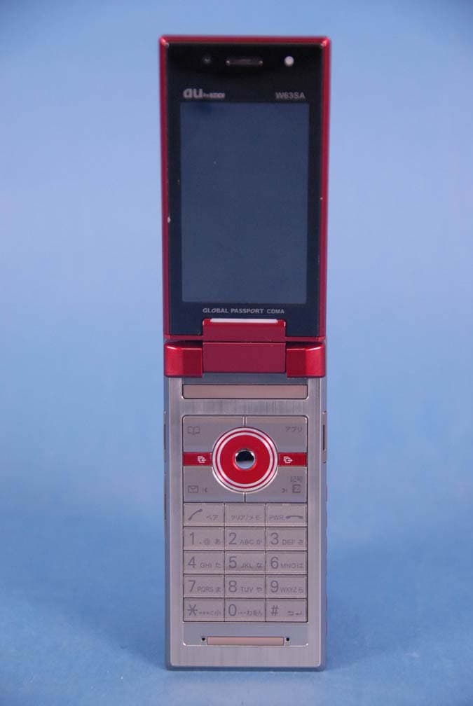
AEZW63SA
Mar 30, 2008Cellular CDMA Phone with Bluetooth
Equipment Class
TNE - Licensed Non-Broadcast Transmitter Held to Ear
AEZSCP-3800
Mar 09, 2008Cellular/ PCS CDMA Phone with Bluetooth
Equipment Class
JBP - Part 15 Class B Computing Device Peripheral
AEZSCP-25H
Sep 12, 2007Cellular/ PCS CDMA Phone with Bluetooth
Equipment Class
DSS - Part 15 Spread Spectrum Transmitter
AEZCPE-400-2C0
Jun 14, 2007W-CDMA subscriber terminal
Equipment Class
TNB - Licensed Non-Broadcast Station Transmitter
AEZNVM-4070
Jun 04, 2007PND (Personal Navigation Device)
Equipment Class
DXT - Part 15 Low Power Transceiver, Rx Verified