AEZSCP-72HDual-Band Analog/ PCS Phone (AMPS/CDMA)
Sanyo Electric Co Ltd
Click to zoom
Application Details
- Equipment Class
- PCE - PCS Licensed Transmitter held to ear
- Date of Grant
- Jun 19, 2003
- Application Purpose
- Original Equipment
- Date of Application
- Jun 19, 2003
- Equipment Note
- Dual-Band Analog/ PCS Phone (AMPS/CDMA)
- Frequency Range
- 1851.25000000 - 1908.75000000
- Company
- Sanyo Electric Co Ltd
- Country
- United States
Documents & Files
Document Text
Text extracted from the exhibit documents filed with the FCC. Open a document above to read the original.
Attestation Statements
SANYO Electric Co., Ltd. Multimedia Company Tel: +81-72-870-6288 Personal Telecommunication Division Fax: +81-72-870-6084 AFFIDAVIT FOR ESN PROTECTION OF CELLULAR MOBILE TELEPHONES Date: August 30, 2001 We hereby certify that the Handheld Portable Cellular Telephone, FCC ID: AEZSCP-72H is so designed that it complies with all the requirements for ESN protection specified in Section 22.919. a) The transmitter in service has a unique ESN. b) The ESN host component is permanently attached to a main circuit board of the mobile transmitter and the integrity of the unit operating software cannot be altered. The ESN is plated from fraudulent contact and tampering. The ESN is encoded using multiplication by a polynomial and the ESN data programmed in the memory with other information. c) The ESN is factory-set and cannot be altered, transferred, removed or otherwise able to be manipulated. Cellular mobile equipment is specifically designed such that any attempt to remove, tamper with, or change the ESN chip, its logic system, or firmware originally programmed by the manufacturer will render the mobile transmitter inoperative. Sincerely, Eiji Kotobuki General Manager Personal Telecommunication Division Multimedia Company SANYO Electric Co., Ltd.
Attestation Statements
SANYO Electric Co., Ltd. Multimedia Company Tel: +81-72-870-6288 Personal Telecommunication Division Fax: +81-72-870-6084 August 30, 2002 Federal Communications Commission Equipment Authorization Branch 7435 Oakland Mills Road Columbia, MD 21046 In re: SANYO Electric Co., Ltd. FCC ID: AEZSCP-72H Dual Band Cellular Phone (Cellular Band AMPS and PCS Band CDMA) Request for Confidentiality Gentlemen: In accordance with 0.459 of CFR 47, Sanyo Electric Co., Ltd. hereby requests confidentiality of the Block Diagram (Attachment I), Schematic Diagrams (Attachment J) and Part lists (Attachment K) in the attached test report. These documents contain detailed system and equipment description and related information about the product which Sanyo Electric Co., Ltd. considers to be proprietary, confidential, and a custom design and, otherwise, would not release to the general public. Since this design is a basis from which future technological products will evolve, Sanyo Corporation considers this information to be of benefit to its competitors, and that the disclosure of the information in these documents would give competitors an unfair advantage in the market. Sincerely, Eiji Kotobuki General Manager Personal Telecommunication division Multimedia Company SANYO Electric Co., Ltd.
Cover Letter(s)
June 20, 2003 Federal Communications Commission Equipment Approval Services 7435 Oakland Mills Road Columbia, MD 21046 SUBJECT: SANYO Electric Co., Ltd. FCC ID: AEZSCP-72H Part 22/24 Certification Gentlemen: Attached herewith, on behalf of SANYO Electric Co., Ltd., is an application for Part 22/24 Certification of AEZSCP-72H Dual Band Analog/PCS phone. Attached is the applicant’s Letter of Authorization, Confidentiality Request, E911 compliance statement, measurement report data and plots, RF Exposure measurement report and data, FCC ID label and location, test setup photographs, internal and external photographs, block diagram (confidential), schematic diagrams (confidential), operational description, parts list (confidential), tune-up procedure, and the user's manual. Should you have any questions or comments concerning the above, please contact the undersigned. cc: Mr. Koichi Takahashi Vice President, Marketing SANYO Fisher (USA) Corp.
External Photos
© 2002 PCTEST Lab SANYO FCC ID: AEZSCP-72H Dual-Band Analog/PCS Phone (AMPS/CDMA) © 2002 PCTEST Lab SANYO FCC ID: AEZSCP-72H Dual-Band Analog/PCS Phone (AMPS/CDMA) © 2002 PCTEST Lab SANYO FCC ID: AEZSCP-72H Dual-Band Analog/PCS Phone (AMPS/CDMA) © 2002 PCTEST Lab SANYO FCC ID: AEZSCP-72H Dual-Band Analog/PCS Phone (AMPS/CDMA) © 2002 PCTEST Lab SANYO FCC ID: AEZSCP-72H Dual-Band Analog/PCS Phone (AMPS/CDMA) © 2002 PCTEST Lab SANYO FCC ID: AEZSCP-72H Dual-Band Analog/PCS Phone (AMPS/CDMA) © 2002 PCTEST Lab SANYO FCC ID: AEZSCP-72H Dual-Band Analog/PCS Phone (AMPS/CDMA) © 2002 PCTEST Lab SANYO FCC ID: AEZSCP-72H Dual-Band Analog/PCS Phone (AMPS/CDMA) © 2002 PCTEST Lab SANYO FCC ID: AEZSCP-72H Dual-Band Analog/PCS Phone (AMPS/CDMA) © 2002 PCTEST Lab SANYO FCC ID: AEZSCP-72H Dual-Band Analog/PCS Phone (AMPS/CDMA) © 2002 PCTEST Lab SANYO FCC ID: AEZSCP-72H Dual-Band Analog/PCS Phone (AMPS/CDMA)
ID Label/Location Info
© 2002 PCTEST Lab FCC ID SAMPLE LABEL & LOCATION LABELLING REQUIREMENTS PER §§ 2.925 The Label shown shall be permanently affixed at a conspicuous location on the device and be readily visible to the user at the time of purchase. (SEE NEXT PAGE)
Internal Photos
© 2002 PCTEST Lab SANYO FCC ID: AEZSCP-72H Dual-Band Analog/PCS Phone (AMPS/CDMA) © 2002 PCTEST Lab SANYO FCC ID: AEZSCP-72H Dual-Band Analog/PCS Phone (AMPS/CDMA) © 2002 PCTEST Lab SANYO FCC ID: AEZSCP-72H Dual-Band Analog/PCS Phone (AMPS/CDMA) © 2002 PCTEST Lab SANYO FCC ID: AEZSCP-72H Dual-Band Analog/PCS Phone (AMPS/CDMA) © 2002 PCTEST Lab SANYO FCC ID: AEZSCP-72H Dual-Band Analog/PCS Phone (AMPS/CDMA) © 2002 PCTEST Lab SANYO FCC ID: AEZSCP-72H Dual-Band Analog/PCS Phone (AMPS/CDMA) © 2002 PCTEST Lab SANYO FCC ID: AEZSCP-72H Dual-Band Analog/PCS Phone (AMPS/CDMA) © 2002 PCTEST Lab SANYO FCC ID: AEZSCP-72H Dual-Band Analog/PCS Phone (AMPS/CDMA) © 2002 PCTEST Lab SANYO FCC ID: AEZSCP-72H Dual-Band Analog/PCS Phone (AMPS/CDMA) © 2002 PCTEST Lab SANYO FCC ID: AEZSCP-72H Dual-Band Analog/PCS Phone (AMPS/CDMA)
Operational Description
Applicant: SANYO Electric CO., LTD. Transmitter Type: AEZSCP-72H EXHIBIT xx 1 / 4 TECHNICAL DESCRIPTION This transmitter has been specially designed for the Domestic Personal Communication Service (PCS band CDMA) and the Domestic Cellular Radiotelephone Communication Service (Cellular band AMPS). [PCS band CDMA ] The rated maxim um power output for CDMA is 0.5 watts with the capability of reducing the maximum power in a step of 1 dB on command from the base station. The transmitter output is confirmed correspond to the received power level of the mobile station. Each power level is maintained within +0.1 /-4 dB of its nominal level over the temperature range from –30 to +60 degrees centigrade and +14 –14% change of the supply voltage. This transmitter operates in the frequency range of 1851.250 MHz to 1908.250 MHz. The frequencies are generated by Phase Locked Loop Frequency Synthesizers, which are controlled by the closest base station in the system. The handset causes the frequency stability of carrier according to the frequency from the base station to become less than + 150 Hz. The transmitter is equipped with a voice processing and a Coding. The Voice processing (included in IC210) samples a voice signal and processes the voice data, which is included in MSM (Mobile Subscriber Modem) (IC210 ), codes 8K or 13K voice data packet. And MSM formats the modulated signals with a voice data packet. The modulation is the Quadrature modulation. The I and Q signals are shaped by the filters whose function is included in MSM and are added and up-frequency. The signals are transformed to RF IC (IC130). The D/A Converters, which are included in IC210, generate analog I and Q signals. The low pass filters that are included in IC210 shape the analog I and Q signals to limit Band width 1.25MHz. The carrier frequency of transmitter is generated by a TX PLL (Phase Locked Loop) circuit and a local PLL circuit. TX PLL circuit consists of a VCO that is included IC X1402, a frequency synthesizer IC (X1402), a loop filter, and a reference frequency oscillator (TCXO module X1400). The TX UP mixer is incorporated in the TX Control IC (IC130). The local PLL circuit consists of a VCO (in X1402), the frequency synthesizer IC (IC23), the loop filter, and the reference frequency oscillator. The TX up mixer is in the TX control IC (IC130). For the TCXO system, see EXHIBIT XX. The Frequency Synthesizer IC (X1402) and IC130 make frequencies and IC (X1402) has a programmable divider, a reference divider, a phase comparator, and a change pump. The programmable divider of X1402, which is controlled by MSM (IC210) included CPU, provides a signal to the phase comparator by dividing an output of the VCO (in X1402). The divider of IC130 is a fixed divider and it provides a signal to the phase comparator by dividing the VCO frequency the fixed number. The reference divider provides a reference signal to the phase comparator by dividing an output of the TCXO system. The phase comparator controls a frequency of the VCO through the charge pump Applicant: SANYO Electric CO., LTD. Transmitter Type: AEZSCP-72H EXHIBIT xx 2 / 4 and Loop filter so that the phase of the signal from the programmable divider corresponds to the phase of the reference signal. The frequency of the VCO (in X1402) for RF-PLL and the VCO (in IC130) for IF PLL, and the TCXO system stability are controlled by MSM5100 (IC210). The baseband signal is generated by mixing with the TX_IF-PLL output on the TX control (IC130), and provided to the Buffer Amp. (TR2, TR3) through a bandpass filter. The power amplifier circuit, which consists of a PCS Power Amp. (IC334), the bandpass filter, and the power control circuit, amplifies the output from the Buffer Amp. in IC130 and provides at least (MAX) 25.8 dB output. The output of the PCS power amplifier is connected to an isolator, a separator and the duplexer. The Saw filter (SW) is connected to an antenna terminal and an external connector RF terminal. The output of the power amplifier provides adequate margin to compensate for losses in the duplexer, the isolator, the separator and the SW. The Power Control circuit consists the HDET (D1304 andD1305), an AGC (Auto Gain Control) circuit included in the TX control IC (IC130), an AD converter included in IC210, and a TX control circuit included in MSM5100. The PCS Power Amp. output level, which is detected by HDET is converted into the digital data by the AD converter included in IC15, and is loaded into IC210. The TX power level is confirmed according to the RX power level and a command from the base station. The IC210 detects the RX power level in IC and generates an AGC signal corresponding to the TX power level, and adjusts the signal according to a command from the base station and a read value of HDET, and then provides it into the AGC circuit in IC130. The TX power level of the transmitter is controlled by changing the Amplitude of the output power level in AGC circuit according to the AGC control voltage value. IC210 continuously monitors the power output at the output of HDET. The above is used to adjust the maximum TX power. An AGC value is modified by a monitor value, and it doesn’t exceed a set TX LIMIT value. The transmitter is controlled by a signal from the IC210. The TX control IC (IC130), the frequency synthesizer IC (IC130 and X130) and PCS Power Amp is enabled. Applicant: SANYO Electric CO., LTD. Transmitter Type: AEZSCP-72H EXHIBIT xx 3 / 4 [AMPS mode] The rated maximum power output is 0.4 watts with the capability of reducing the maximum power in five steps of 4dB each on command from a Base Station. Each power level is maintained within +0.07/-4dB of its nominal level per the temperature range from –30 to +60 degrees Centigrade and +14 –14% change of the supply voltage, accumulative. This transmitter operates in the frequency range of 824.04 to 848.97 MHz. The frequencies are generated by Phase Locked Loop Frequency Synthesizers which are controlled …
Text truncated - open the document above for the full version.
Parts List/Tune Up Info
0AS16343000X11PAGE AEZSCP-72H (SCP-7200) Adjustment Discription for Mass production. 1-163-430-00SCP-7200/H.US Eng. SectionSANYO Telecommunication Co.,Ltd Technical Engineering Department RF Section NAMEA.Shimahara / H.Araki / M.Ichi No.Contents 1Set-Up for Tune-Up and Adjustment of Transmitter 2Alignment Procedure 3Adjust Value 4Measurement Specification of Adjustment PAGE 2 1. Set-Up for Tune-Up and Adjustment of Transmitter PC-OUT/POWER-SUPPLY RF Cable *HP8924 Must need to Calibrate before Adjustment. 1. Power on and Setup to Config Menu(Shift + Test Key). 2. Setup to Service Menu and Change to "TEMP_SENSE" of Voltmeter Connection . 3. After 30 minutes, Check for TEMP_SENSE Meter Stabilization or 0.5V(50 degree C 4. Setup to RF chan std is "US PCS" and Alt pwr ms cal band is "MS AMPS" . SCP-7200 Handset5. Change to CDMA Scrns and Change AVG Power mode to Chan Power mode. Shield Box6. Start Calibration(About 3 minutes : Transmitter tester calibration). 7. Next, Return to Config Menu and Start Rfgen Lvl Calibration(few Seconds). GPIB Control Cable DC-POWER SUPPLY Controller Personal Computer HP5515 CDMA Mobile Station Test Set PAGE 3 2Alignment Procedure (1)Adjustment Procedure Controller(Personal Computer) SETUPIAMPS Adjustment ModeIIPCS Adjustment Mode SCP-7200 Handset Connect,Power ONTx-Power ADJ.Rx-RASRAM ADJ. *(A) Division of NG IAMPS Mesurement ModeRSSI ADJ.Rx-Frequency ADJ. *(C) NG Adjustment/Adjustment Value SettingFrequency Sens. ADJ.Tx-RASRAM,LIMIT ADJ. NV Value Compare with Specification Tx Frequency ADJ. OK Write Value to EEPROM END Division of NGTx Frequency ADJ. IIPCS Adjustment Mode Adjustment/Adjustment Value Setting NG(4) Limit Frequency ADJ. NV Value Compare with Specification OKEND Write Value to EEPROM END POWER OFF/Get Out SCP-7200 HandsetWhen use the program for reduction of adjustment, each (A)(B)(C) are adjusted at the same time. (2) High Power Mode *(B) (3) HDET Frequency ADJ *(B) (1) LowPowerMode (Only for Tx-Rasram) (2) High Power Mode *(A) (1) Low Power Mode *(C) 2Alignment Procedure PAGE 4 (2)Measurement Procedure Controller(Personal Computer) SETUPIAMPS Measurement modeIIPCS Measurement mode SCP-7200 Handset Connect,Power ONTx-Frequency Err Rate.Single Tone Desens. Division of NG IAMPS Measurement ModeTx-Power Lv (0-7)AWGN Measurement Mode Setup and MesurementDeviation LimittingFrquency ERR. Rate NG Adjustment Value Compare with Specification Wideband DataOpen-Loop Power OK POWER OFF/Get Out SCP-7200 HandsetSAT LevelClosed-Loop Power Audio LevelMinimum Cntl.Power PCS Measurement System SETUP Division of NGAudio DistortionReceiver Sensitivity IIPCS Measurement Mode SINAD(799,383,991ch)Maximum Output Power Measurement Mode Setup and Mesurement NGTx Conducted-SpuriusConducted Spurious Adjustment Value Compare with Specification OKENDEND POWER OFF/Get Out SCP-7200 Handset END PAGE 6 2.PCS RX Adjustment ITEMSub-ITEMHandset Setup(Internal Setup)HP5515 SetupAdj. ValueAccuracy of NV-Value Rx-RASRAMTable 1Normal ModeCDMA Ch=563 :SG LV=-106.0dBm-106.0dBm AdjustmentTable 2OFF Line Mode SG LV=-100.6dBm-100.6dBm Table 3 SG LV=-95.3dBm-95.3dBm Table 4SG LV=-90.0dBm-90.0dBm Table 5SG LV=-84.7dBm-84.7dBm Table 6SG LV=-79.4dBm-79.4dBm Table 7SG LV=-74.1dBm-74.1dBm Table 8SG LV=-68.8dBm-68.8dBm Table 9SG LV=-63.5dBm-63.5dBm Table 10SG LV=-58.1dBm-58.1dBm Table 11SG LV=-52.8dBm-52.8dBm Table 12SG LV=-47.5dBm-47.5dBm Table 13SG LV=-42.2dBm-42.2dBm Table 14SG LV=-36.9dBm-36.9dBm Table 15SG LV=-31.6dBm-31.6dBm Table 16SG LV=-26.3dBm-26.3dBm Table 17SG LV=-21.0dBm-21.0dBm RX AGC FrequencyBk 0=38chNormal ModeRF INPUT(SG) LV=-63.5dBmAGC DIFF. AdjustmentBk 1=113chReference ch :1163chChange to Channel 16 Time.AGC DIFF. Bk 2=188chDeference of Center ch AGCsym.AGC DIFF. Bk 3=263chChange to Channel 16 Time.AGC DIFF. Bk 4=338chOFF Line ModeAGC DIFF. Bk 5=413chAGC DIFF. Bk 6=488chAGC DIFF. Bk 7=563chAGC DIFF. Bk 8=638chAGC DIFF. Bk 9=713chAGC DIFF. Bk10=788chAGC DIFF. Bk11=863chAGC DIFF. Bk12=938chAGC DIFF. Bk13=1013chAGC DIFF. Bk14=1088chAGC DIFF. Bk15=1163chREF CH. 3.Adjustment Value PAGE 7 3.PCS TX & TX-LIMIT Adjustment ITEM Sub-ITEM Handset Setup(Internal Setup) HP5515 Setup Adj. Value Accuracy of NV-Value Tx-RASRAMNomal Test ModePCS Ch=1163ch +23.5dBm AdjustmentSG level is ccording to the transmission-50.0dBm power level of MS Adjusted by Low Power Mode & High Power Mode &TOTAL:36Parametor Symbol -50.0dBm +23.5dBm Tx-LimitTable 1PCS Ch=1163ch+8.75dBm AdjustmentTable 2+10.1dBm Table 3+11.4dBm *Only forTable 4+12.7dBm High Power ModeTable 5+14.1dBm Table 6+15.4dBm Table 7+16.7dBm Table 8+18.1dBm Table 9+19.4dBm Table 10+20.7dBm Table 11+22.1dBm Table 12+23.4dBm Table 13 +23.5dBm Table 14 +23.5dBm Table 15 +23.5dBm Table 16 +23.5dBm OFFSET Offset : 16.7dB(Table 7) +16.7dBm SPN Spn : 26.0dBm(Table 14) +23.5dBm 3.Adjustment Value PAGE 8 4.PCS(CDMA)Tx AGC Frequency Adjustment and Tx Limit Frequency Adjustment. TX AGC FrequencyNomal Test ModeRF INPUT(SG) LV=Low:-63.5dBm AdjustmentReference ch :1163ch High:-92.0dBm Difference of Center ch AGCsym.Change to Channel 16 Time. Adjusted byChange to Channel 16 Time. Low Power Mode &BK 0~14 *1 High Power Mode(ch)Tx-Pow diff. Bk15=1163ch HDET FrequencyNomal Test ModeRF INPUT(SG) LV=HDET:-92dBm AdjustmentReference ch :1163chChange to Channel 16 Time. Difference of Center ch AGCsym. Change to Channel 16 Time. BK 0~14 *1 (ch)Tx-Pow diff.HDET diff. Difference of HDET Bk15=1163ch TX Limit FrequencyNomal Test ModeRF INPUT(SG) LV=-92.0dBm AdjustmentReference ch :1163chChange to Channel 16 Time. Difference of Center ch AGCsym. Change to Channel 16 Time. BK 0~14 *1*2 (ch) Bk15=1175ch*3 12Symb=1.0dBm Supplementary value:Difference of TX-power change to symb. Supplementary value:Difference of HDET value change to AGC PAGE 9 4.Measurement Specification of Adjustment 1.AMPS Mesurement SpecificationSCP-7200 Measurement ItemStandard ItemIS98A Standard SpecMeasurement SpecMeasurement ConditionMeasurement ChannelOthers Tx-Frequency ErrTIA/EIA-98-B:3.1.2< ±2.5ppm< ±2.…
Text truncated - open the document above for the full version.
RF Exposure Info
PCTEST ENGINEERING LABORATORY, INC. 6660 – B Dobbin Road • Columbia, MD 21045 • USA Telephone 410.290.6652 / Fax 410.290.6654 http://www.pctestlab.com (email: [email protected]) CERTIFICATE OF COMPLIANCE (SAR EVALUATION) PCTEST SAR REPORT FCC CERTIFICATION Reviewed by: Quality Manager SAR Filename: SAR-220826470.AEZ Test Dates: Aug. 26-30, 2002 Phone Type: Dual-Band Analog/PCS FCC ID: AEZSCP-72H Page 1 of 31 © 2003 PCTEST Engineering Laboratory, Inc APPLICANT NAME & ADDRESS: DATE & LOCATION OF TESTING: SANYO ELECTRIC CO., LTD. Dates of Tests: August 26-30, 2002 c/o SANYO Fisher (USA) Corp. Test Report S/N: SAR.220826470.AEZ 218 Route 17 North Test Site: PCTEST Lab, Columbia MD Rochelle Park, NJ 07662 Attn: Mr. Koichi Takahashi, V.P. Marketing SANYO Fisher (USA) Corporation) FCC ID: AEZSCP-72H APPLICANT: SANYO ELECTRIC CO., LTD. EUT Type: Dual-Band Analog/PCS Phone (AMPS/CDMA) Tx Frequency: 824.04 – 848.97 MHz (AMPS) / 1851.25 – 1908.75 MHz (PCS CDMA) Rx Frequency: 869.04 – 893.97 MHz (AMPS) / 1931.25 – 1988.75 MHz (PCS CDMA) Max. RF Output Power: 0.618 W ERP AMPS (27.913 dBm) / 25.5 dBm Conducted 0.468 W EIRP PCS CDMA (26.701 dBm)/ 23.5 dBm Conducted Max. SAR Measurement: 1.410 W/kg AMPS Head SAR; 0.458 W/kg AMPS Body SAR; 1.420 W/kg PCS CDMA Head SAR; 1.220 W/kg PCS CDMA Body SAR 0.285 W/kg PCS CDMA Mouth SAR Trade Name/Model(s): SCP-7200 FCC Classification: Licensed Portable Transmitter Held to Ear (PCE) FCC Rule Part(s): §2.1093; FCC/OET Bulletin 65 Supplement C [July 2001] Application Type: Certification Test Device Serial No.: identical prototype [S/N: # 1] This wireless portable device has been shown to be capable of compliance for localized specific absorption rate (SAR) for uncontrolled environment/general population exposure limits specified in ANSI/IEEE Std. C95.1-1992 and had been tested in accordance with the measurement procedures specified in FCC/OET Bulletin 65 Supplement C (2001) and IEEE Std. 1528-200X (Draft 6.4, July 2001). I attest to the accuracy of data. All measurements reported herein were performed by me or were made under my supervision and are correct to the best of my knowledge and belief. I assume full responsibility for the completeness of these measurements and vouch for the qualifications of all persons taking them. Grant conditions: Output is ERP for Part 22 and EIRP for Part 24. SAR compliance for body- worn operating configuration is limited to the specific belt-clip/holster described in this filing. Push-to-talk (PTT) operating configuration is based on a separation distance of 2.5 cm between the front of the unit and the body of the user. End-users must be informed of the body-worn operating requirements for satisfying RF exposure compliance. PCTEST certifies that no party to this application has been denied the FCC benefits pursuant to Section 5301 of the Anti-Drug Abuse Act of 1988, 21 U.S.C. 862. 220826470.AEZ PCTEST SAR REPORT FCC CERTIFICATION Reviewed by: Quality Manager SAR Filename: SAR-220826470.AEZ Test Dates: Aug. 26-30, 2002 Phone Type: Dual-Band Analog/PCS FCC ID: AEZSCP-72H Page 2 of 31 © 2003 PCTEST Engineering Laboratory, Inc TABLE OF CONTENTS 1. INTRODUCTION ..........................................................................................3 SAR DEFINITION .........................................................................................3 2. SAR MEASUREMENT SETUP...........................................................................4 Robotic System..............................................................................................4 System Hardware...........................................................................................4 System Electronics..........................................................................................4 3. DASY3 E-FIELD PROBE SYSTEM......................................................................5 Probe Measurement System.............................................................................5 Probe Specifications.......................................................................................5 4. Probe Calibration Process................................................................................6 Dosimetric Assessment Procedure....................................................................6 Free Space Assessment....................................................................................6 Temperature Assessment.................................................................................6 5. PHANTOM & EQUIVALENT TISSUES..............................................................7 SAM Phantom................................................................................................7 Brain & Muscle Simulating Mixture Characterization..........................................7 Device Holder for Transmitters........................................................................7 6. TEST SYSTEM SPECIFICATIONS.......................................................................8 Automated Test System Specifications...............................................................8 7. DOSIMETRIC ASSESSMENT & PHANTOM SPECS..............................................9 Measurement Procedure.................................................................................9 Specific Anthropomorphic Mannequin (SAM) Specifications...............................9 8. DEFINITION OF REFERENCE POINTS............................................................10 EAR Reference Point.....................................................................................10 Handset Reference Points..............................................................................10 9. TEST CONFIGURATION POSITIONS.............................................................11 Positioning for Cheek/Touch..........................................................................11 Positioning for Ear / 15° Tilt..........................................…
Text truncated - open the document above for the full version.
RF Exposure Info
© 2002 PCTEST Lab SANYO FCC ID: AEZSCP-72H Dual-Band Analog/PCS Phone (AMPS/CDMA) © 2002 PCTEST Lab SANYO FCC ID: AEZSCP-72H Dual-Band Analog/PCS Phone (AMPS/CDMA) © 2002 PCTEST Lab SANYO FCC ID: AEZSCP-72H Dual-Band Analog/PCS Phone (AMPS/CDMA) © 2002 PCTEST Lab SANYO FCC ID: AEZSCP-72H Dual-Band Analog/PCS Phone (AMPS/CDMA) © 2002 PCTEST Lab SANYO FCC ID: AEZSCP-72H Dual-Band Analog/PCS Phone (AMPS/CDMA) © 2002 PCTEST Lab SANYO FCC ID: AEZSCP-72H Dual-Band Analog/PCS Phone (AMPS/CDMA) © 2002 PCTEST Lab SANYO FCC ID: AEZSCP-72H Dual-Band Analog/PCS Phone (AMPS/CDMA) © 2002 PCTEST Lab SANYO FCC ID: AEZSCP-72H Dual-Band Analog/PCS Phone (AMPS/CDMA) © 2002 PCTEST Lab SANYO FCC ID: AEZSCP-72H Dual-Band Analog/PCS Phone (AMPS/CDMA) © 2002 PCTEST Lab SANYO FCC ID: AEZSCP-72H Dual-Band Analog/PCS Phone (AMPS/CDMA) © 2002 PCTEST Lab SANYO FCC ID: AEZSCP-72H Dual-Band Analog/PCS Phone (AMPS/CDMA) © 2002 PCTEST Lab SANYO FCC ID: AEZSCP-72H Dual-Band Analog/PCS Phone (AMPS/CDMA) © 2002 PCTEST Lab SANYO FCC ID: AEZSCP-72H Dual-Band Analog/PCS Phone (AMPS/CDMA) © 2002 PCTEST Lab SANYO FCC ID: AEZSCP-72H Dual-Band Analog/PCS Phone (AMPS/CDMA) © 2002 PCTEST Lab SANYO FCC ID: AEZSCP-72H Dual-Band Analog/PCS Phone (AMPS/CDMA) © 2002 PCTEST Lab SANYO FCC ID: AEZSCP-72H Dual-Band Analog/PCS Phone (AMPS/CDMA) © 2002 PCTEST Lab SANYO FCC ID: AEZSCP-72H Dual-Band Analog/PCS Phone (AMPS/CDMA) © 2002 PCTEST Lab SANYO FCC ID: AEZSCP-72H Dual-Band Analog/PCS Phone (AMPS/CDMA)
Test Report
© 2003 PCTEST Lab SANYO ELECTRIC Co., Ltd. FCC ID: AEZSCP-72H © 2003 PCTEST Lab SANYO ELECTRIC Co., Ltd. FCC ID: AEZSCP-72H © 2003 PCTEST Lab SANYO ELECTRIC Co., Ltd. FCC ID: AEZSCP-72H PCTEST Engineering Lab., Inc. SUBJECT:Modulation CharacteristicsTest Report No.:22/24.220826449.AEZ FCC Part 24/22Test Date:08.26.2002 EUT:SANYO Dual-Band Analog/PCS Phone (AMPS/CDMA) Model:SCP-7200 FCC ID:AEZSCP-72H REFERENCE:1 kHz = 0 dB Modulation Limiting 0 2000 4000 6000 8000 10000 12000 14000 -35-30-25-20-15-10-50 Audio Input Level (dBV) Deviation (Hz) SANYO Dual-Band Analog/PCS Phone (AMPS/CDMA) FCC ID: AEZSCP-72H PCTEST Engineering Lab., Inc. SUBJECT:Modulation CharacteristicsTest Report No.:22/24.220826449.AEZ FCC Part 24/22Test Date:08.26.2002 EUT:SANYO Dual-Band Analog/PCS Phone (AMPS/CDMA) Model:SCP-7200 FCC ID:AEZSCP-72H REFERENCE:1 kHz = 0 dB Frequency Response of Audio Low Pass Filter -90.0 -80.0 -70.0 -60.0 -50.0 -40.0 -30.0 -20.0 -10.0 0.0 10.0 FREQUENCY (Hz) LEVEL (dB) Relative to 1kHz 10k1k 100k SANYO Dual-Band Analog/PCS Phone (AMPS/CDMA) FCC ID: AEZSCP-72H PCTEST Engineering Lab., Inc. SUBJECT:Modulation CharacteristicsTest Report No.:22/24.220826449.AEZ FCC Part 24/22Test Date:08.26.2002 EUT:SANYO Dual-Band Analog/PCS Phone (AMPS/CDMA) Model:SCP-7200 FCC ID:AEZSCP-72H REFERENCE:1 kHz = 0 dB Transmitter Audio Frequency Response -60.00 -50.00 -40.00 -30.00 -20.00 -10.00 0.00 10.00 20.00 FREQUENCY (Hz) LEVEL (dB) Relative to 1kHz 100 1k 10k 100k SANYO Dual-Band Analog/PCS Phone (AMPS/CDMA) FCC ID: AEZSCP-72H
Test Report
PCTEST PT. 22/24 REPORT FCC CERTIFICATION Reviewed By: Quality Manager Test Report S/N: 22/24.220826449.AEZ Test Dates: Aug. 26-30, 2002 Phone Type: Dual-Band Analog/PCS FCC ID: AEZSCP-72H Page 1 of 25 © 2003 PCTEST ENGINEERING LABORATORY, INC. PCTEST Engineering Laboratory, Inc. 6660-B Dobbin Road • Columbia, MD 21045 • U.S.A. TEL (410) 290-6652 • FAX (410) 290-6654 http://www.pctestlab.com CERTIFICATE OF COMPLIANCE FCC Part 24 & 22 Certification SANYO ELECTRIC CO., LTD. Dates of Tests: August 26-30, 2002 c/o SANYO Fisher (USA) Corp. Test Report S/N: 22/24.220826449.AEZ 218 Route 17 North Test Site: PCTEST Lab, Columbia MD Rochelle Park, NJ 07662 Attn: Mr. Koichi Takahashi, V.P. Marketing SANYO Fisher (USA) Corporation) FCC ID AEZSCP-72H APPLICANT SANYO ELECTRIC CO., LTD. Classification: Licensed Portable Transmitter Held to Ear (PCE) FCC Rule Part(s): §24(E), §22(H), §2 EUT Type: Dual-Band Analog/PCS Phone (AMPS/CDMA) Model: SCP-7200 Tx Frequency Range: 824.04MHz – 848.97MHz (AMPS) / 1851.25MHz – 1908.75MHz (PCS CDMA) Rx Frequency Range: 869.04MHz – 893.97MHz (AMPS) / 1931.25MHz – 1988.75MHz (PCS CDMA) Max. RF Output Power: 0.618W ERP AMPS (27.913 dBm) / 0.468 W EIRP PCS CDMA (26.701 dBm) Max. SAR Measurement: 1.410W/kg AMPS Head SAR; 0.458W/kg AMPS Body SAR; 1.420W/kg PCS CDMA Head SAR; 1.220W/kg PCS CDMA Body SAR 0.285 W/kg PCS CDMA Mouth SAR Emission Designator(s): 40K0F8W / 40K0F1D (AMPS), 1M25F9W (CDMA) Test Device Serial No.: identical prototype [S/N: # 1] This equipment has been shown to be capable of compliance with the applicable technical standards as indicated in the measurement report and was tested in accordance with the measurement procedures specified in §2.947. I attest to the accuracy of data. All measurements reported herein were performed by me or were made under my supervision and are correct to the best of my knowledge and belief. I assume full responsibility for the completeness of these measurements and vouch for the qualifications of all persons taking them. Grant conditions: Output is ERP for Part 22 and EIRP for Part 24. SAR compliance for body-worn operating configuration is limited to the specific belt-clip/holster described in this filing. Push-to-talk (PTT) operating configuration is based on a separation distance of 2.5 cm between the front of the unit and the body of the user. End-users must be informed of the body-worn operating requirements for satisfying RF exposure compliance. PCTEST certifies that no party to this application has been denied the FCC benefits pursuant to Section 5301 of the Anti-Drug Abuse Act of 1988, 21 U.S.C. 862. 220826449.AEZ PCTEST PT. 22/24 REPORT FCC CERTIFICATION Reviewed By: Quality Manager Test Report S/N: 22/24.220826449.AEZ Test Dates: Aug. 26-30, 2002 Phone Type: Dual-Band Analog/PCS FCC ID: AEZSCP-72H Page 2 of 25 © 2003 PCTEST ENGINEERING LABORATORY, INC. TABLE OF CONTENTS ATTACHMENT A: COVER LETTER(S) ATTACHMENT B: ATTESTATION STATEMENT(S) ATTACHMENT C: TEST REPORT 1.1 SCOPE 3 2.1 INTRODUCTION 4 3.1 INSERTS 5 4.1 DESCRIPTION OF TESTS 6-9 5.1 EFFECTIVE RADIATED POWER OUTPUT 10 6.1 EQUIVALENT ISOTROPIC RADIATED POWER 11 7.1 RADIATED MEASUREMENTS 12-17 8.1 FREQUENCY STABILITY 18-21 9.1 PLOTS OF EMISSIONS 22 10.1 LIST OF TEST EQUIPMENT 23 11.1 SAMPLE CALCULATIONS 24 12.1 CONCLUSION 25 ATTACHMENT D: TEST PLOTS ATTACHMENT E: FCC ID LABEL / LOCATION ATTACHMENT F: TEST SETUP PHOTOGRAPHS ATTACHMENT G: EXTERNAL PHOTOGRAPHS ATTACHMENT H: INTERNAL PHOTOGRAPHS ATTACHMENT I: BLOCK DIAGRAM(S) ATTACHMENT J: SC…
Text truncated - open the document above for the full version.
Contact Information
Applicant
Hideaki Mukaida
Technical Contact
PCTEST Engineering Lab., Inc.Randy Ortanez
[email protected]410-290-6652
6660-B Dobbin Road · Columbia, Maryland · United States
Test Firm
PCTEST Engineering Laboratory, Inc.Randy Ortanez
Technical Specifications
| # | Rule Parts | Frequency Range | Power Output | Emission | Tolerance |
|---|---|---|---|---|---|
| 3 | 24E | 1.85 GHz - 1.91 GHz | 468.00 mW | 1M25F9W | 2.5 ppm |
Other Applications from Sanyo Electric Co Ltd
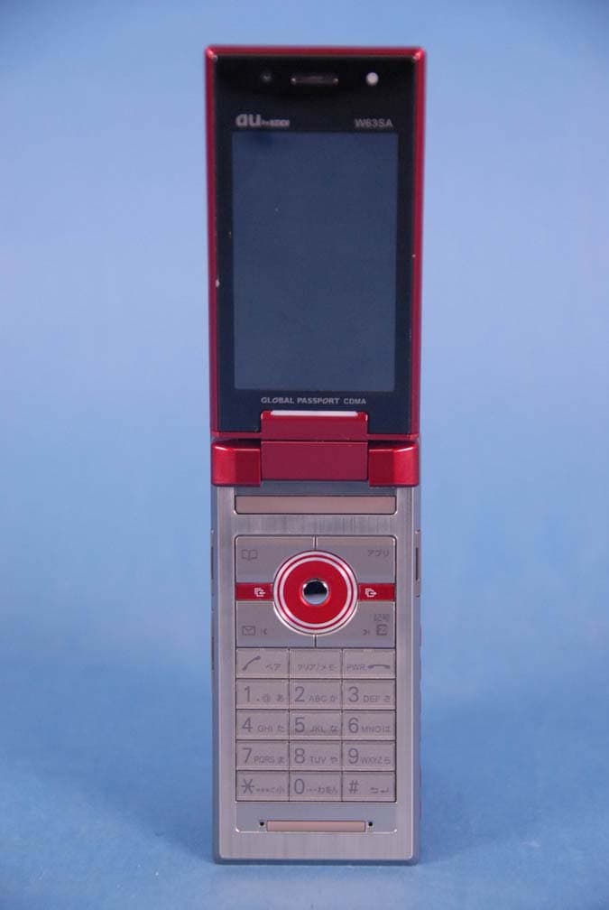
AEZW63SA
Mar 30, 2008Cellular CDMA Phone with Bluetooth
Equipment Class
TNE - Licensed Non-Broadcast Transmitter Held to Ear
AEZSCP-3800
Mar 09, 2008Cellular/ PCS CDMA Phone with Bluetooth
Equipment Class
JBP - Part 15 Class B Computing Device Peripheral
AEZSCP-25H
Sep 12, 2007Cellular/ PCS CDMA Phone with Bluetooth
Equipment Class
DSS - Part 15 Spread Spectrum Transmitter
AEZCPE-400-2C0
Jun 14, 2007W-CDMA subscriber terminal
Equipment Class
TNB - Licensed Non-Broadcast Station Transmitter
AEZNVM-4070
Jun 04, 2007PND (Personal Navigation Device)
Equipment Class
DXT - Part 15 Low Power Transceiver, Rx Verified