AEZSCP-81HTri-Mode Dual-Band Analog/ PCS Phone (AMPS/ CDMA)
Sanyo Electric Co Ltd
Click to zoom
Application Details
- Equipment Class
- PCE - PCS Licensed Transmitter held to ear
- Date of Grant
- Mar 17, 2003
- Application Purpose
- Original Equipment
- Date of Application
- Mar 17, 2003
- Equipment Note
- Tri-Mode Dual-Band Analog/ PCS Phone (AMPS/ CDMA)
- Frequency Range
- 1851.25000000 - 1908.75000000
- Company
- Sanyo Electric Co Ltd
- Country
- United States
Documents & Files
Document Text
Text extracted from the exhibit documents filed with the FCC. Open a document above to read the original.
Users Manual
User’s Guide Vision-enabled PCS Phone SCP-8100 Table of Contents Welcome to Sprint . . . . . . . . . . . . . . . . . . . . . . . . . . . . . . . . . . . . . . . . . . . .i Introduction to this User’s Guide . . . . . . . . . . . . . . . . . . . . . . . . . . . .iii Section 1: Getting Started . . . . . . . . . . . . . . . . . . . . . . . . . . . . . . . . . . . .1 1A. Setting Up Service . . . . . . . . . . . . . . . . . . . . . . . . . . . . . . . . . . . . . . . . . . . . . . . . . . . .3 Getting Started With PCS Service . . . . . . . . . . . . . . . . . . . . . . . . . . . . . . . . . . . . .4 Setting Up Your Voicemail . . . . . . . . . . . . . . . . . . . . . . . . . . . . . . . . . . . . . . . . . . .5 Getting Help . . . . . . . . . . . . . . . . . . . . . . . . . . . . . . . . . . . . . . . . . . . . . . . . . . . . . . . .5 Section 2: Understanding Your PCS Phone . . . . . . . . . . . . . . . . . . .7 2A. Your PCS Phone: The Basics . . . . . . . . . . . . . . . . . . . . . . . . . . . . . . . . . . . . . . . . . .9 Front View of Phone . . . . . . . . . . . . . . . . . . . . . . . . . . . . . . . . . . . . . . . . . . . . . . . .10 Viewing the Display Screen . . . . . . . . . . . . . . . . . . . . . . . . . . . . . . . . . . . . . . . . .12 Features of Your PCS Phone by SANYO SCP-8100 . . . . . . . . . . . . . . . . . . . . .13 Turning Your Phone ON and OFF . . . . . . . . . . . . . . . . . . . . . . . . . . . . . . . . . . . .14 Using the Battery . . . . . . . . . . . . . . . . . . . . . . . . . . . . . . . . . . . . . . . . . . . . . . . . . . .14 Displaying Your Phone Number . . . . . . . . . . . . . . . . . . . . . . . . . . . . . . . . . . . . .17 Making and Answering Calls . . . . . . . . . . . . . . . . . . . . . . . . . . . . . . . . . . . . . . . .17 Making Calls . . . . . . . . . . . . . . . . . . . . . . . . . . . . . . . . . . . . . . . . . . . . . . . . . . . . . .17 Answering Calls . . . . . . . . . . . . . . . . . . . . . . . . . . . . . . . . . . . . . . . . . . . . . . . . . .18 Changing Ringer Volume . . . . . . . . . . . . . . . . . . . . . . . . . . . . . . . . . . . . . . . . . .19 Adjusting Volume During a Conversation . . . . . . . . . . . . . . . . . . . . . . . . . . .19 Muting a Call . . . . . . . . . . . . . . . . . . . . . . . . . . . . . . . . . . . . . . . . . . . . . . . . . . . . .19 Missed Call Notification . . . . . . . . . . . . . . . . . . . . . . . . . . . . . . . . . . . . . . . . . . .20 Calling Emergency Numbers . . . . . . . . . . . . . . . . . . . . . . . . . . . . . . . . . . . . . .20 Dialing Options . . . . . . . . . . . . . . . . . . . . . . . . . . . . . . . . . . . . . . . . . . . . . . . . . . .21 In-Call Options . . . . . . . . . . . . . . . . . . . . . . . . . . . . . . . . . . . . . . . . . . . . . . . . . . .22 End-of-Call Options . . . . . . . . . . . . . . . . . . . . . . . . . . . . . . . . . . . . . . . . . . . . . . .23 Saving a Phone Number . . . . . . . . . . . . . . . . . . . . . . . . . . . . . . . . . . . . . . . . . . .24 Finding a Phone Number . . . . . . . . . . . . . . . . . . . . . . . . . . . . . . . . . . . . . . . . . .25 Dialing and Saving Phone Numbers With Pauses . . . . . . . . . . . . . . . . . . . .25 Four-Digit Dialing . . . . . . . . . . . . . . . . . . . . . . . . . . . . . . . . . . . . . . . . . . . . . . . . .26 Dialing From the Internal Phone Book . . . . . . . . . . . . . . . . . . . . . . . . . . . . . .26 Using One-Touch Speed Dialing . . . . . . . . . . . . . . . . . . . . . . . . . . . . . . . . . . . .27 2B. Controlling Your Phone’s Settings . . . . . . . . . . . . . . . . . . . . . . . . . . . . . . . . . . .29 Sound Settings . . . . . . . . . . . . . . . . . . . . . . . . . . . . . . . . . . . . . . . . . . . . . . . . . . . . .30 Ringer Types . . . . . . . . . . . . . . . . . . . . . . . . . . . . . . . . . . . . . . . . . . . . . . . . . . . . .30 Restricting Calls . . . . . . . . . . . . . . . . . . . . . . . . . . . . . . . . . . . . . . . . . . . . . . . . . . . .56 Using Special Numbers . . . . . . . . . . . . . . . . . . . . . . . . . . . . . . . . . . . . . . . . . . . . .57 Erasing the Internal Phone Book . . . . . . . . . . . . . . . . . . . . . . . . . . . . . . . . . . . .57 Erasing the Downloads . . . . . . . . . . . . . . . . . . . . . . . . . . . . . . . . . . . . . . . . . . . . .58 Resetting Your Phone . . . . . . . . . . . . . . . . . . . . . . . . . . . . . . . . . . . . . . . . . . . . . .58 Resetting Your Pictures Account . . . . . . . . . . . . . . . . . . . . . . . . . . . . . . . . . . . .58 Resetting and Locking Your Phone through SMS . . . . . . . . . . . . . . . . . . . . . .59 2D, Controlling Your Roaming Experience . . . . . . . . . . . . . . . . . . . . . . . . . . . . . .61 Understanding Roaming . . . . . . . . . . . . . . . . . . . . . . . . . . . . . . . . . . . . . . . . . . . .62 Setting Your Phone’s Roam Mode . . . . . . . . . . . . . . . . . . . . . . . . . . . . . . . . . . .64 Controlling Roaming Charges Using Call Guard . . . . . . . . . . . . . . . . . . . . . .65 2E. Navigating Through Menus . . . . . . . . . . . . . . . . . . . . . . . . . . . . . . . . . . . . . . . . . .67 Menu Navigation . . . . . . . . . . . . . . . . . . . . . . . . . . . . . . . . . . . . . . . . . . . . . . . . . . .68 Menu Structure . . . . . . . . . . . . . . . . . . . . . . . . . . . . . . . . . . . . . . . . . . . . . . . . . . . .68 Viewing the Menus . . . . . . . . . . . . . . . . . . . . . . . . . . . . . . . . . . . . . . . . . . . . . . . . .69 2F. Managing Call History . . . . . . . . . . . . . . . . . . . . . . . . . . . . . . . . . . . . . . . . . . . . . . .71 Viewing History . . . . . . . . . . . . . . . . . . . . . . . . . . . . . . . . . . . . . . . . . . . . . . . . . . .72 Call History Options . . . . . . . . . . . . . . . . . . . . . . . . . . . . . . . . . . . . . . . . . . . . . . . .72 Making a Call From Call History . . . . . . . . . . . . . . . . . . . . …
Text truncated - open the document above for the full version.
External Photos
© 2003 PCTEST Lab SANYO FCC ID: AEZSCP-81H (Model: SCP-8100) Tri-Mode Dual-Band Analog/PCS Phone (AMPS/CDMA) © 2003 PCTEST Lab SANYO FCC ID: AEZSCP-81H (Model: SCP-8100) Tri-Mode Dual-Band Analog/PCS Phone (AMPS/CDMA) © 2003 PCTEST Lab SANYO FCC ID: AEZSCP-81H (Model: SCP-8100) Tri-Mode Dual-Band Analog/PCS Phone (AMPS/CDMA) © 2003 PCTEST Lab SANYO FCC ID: AEZSCP-81H (Model: SCP-8100) Tri-Mode Dual-Band Analog/PCS Phone (AMPS/CDMA) © 2003 PCTEST Lab SANYO FCC ID: AEZSCP-81H (Model: SCP-8100) Tri-Mode Dual-Band Analog/PCS Phone (AMPS/CDMA) © 2003 PCTEST Lab SANYO FCC ID: AEZSCP-81H (Model: SCP-8100) Tri-Mode Dual-Band Analog/PCS Phone (AMPS/CDMA) © 2003 PCTEST Lab SANYO FCC ID: AEZSCP-81H (Model: SCP-8100) Tri-Mode Dual-Band Analog/PCS Phone (AMPS/CDMA) © 2003 PCTEST Lab SANYO FCC ID: AEZSCP-81H (Model: SCP-8100) Tri-Mode Dual-Band Analog/PCS Phone (AMPS/CDMA)
ID Label/Location Info
PCTEST PT. 22/24 REPORT FCC CERTIFICATION Reviewed By: Quality Manager Test Report S/N: 22/24.230224093.AEZ Test Dates: Feb. 24-28, 2003 EUT Type: Tri-Mode Dual-Band Phone FCC ID: AEZSCP-81H Page 1 of 1 FCC ID SAMPLE LABEL & LOCATION LABELLING REQUIREMENTS The Label shown shall be permanently affixed at a conspicuous location on the device and be readily visible to the user at the time of purchase. (SEE NEXT PAGE)
Internal Photos
© 2003 PCTEST Lab SANYO FCC ID: AEZSCP-81H (Model: SCP-8100) Tri-Mode Dual-Band Analog/PCS Phone (AMPS/CDMA) © 2003 PCTEST Lab SANYO FCC ID: AEZSCP-81H (Model: SCP-8100) Tri-Mode Dual-Band Analog/PCS Phone (AMPS/CDMA) © 2003 PCTEST Lab SANYO FCC ID: AEZSCP-81H (Model: SCP-8100) Tri-Mode Dual-Band Analog/PCS Phone (AMPS/CDMA) © 2003 PCTEST Lab SANYO FCC ID: AEZSCP-81H (Model: SCP-8100) Tri-Mode Dual-Band Analog/PCS Phone (AMPS/CDMA) © 2003 PCTEST Lab SANYO FCC ID: AEZSCP-81H (Model: SCP-8100) Tri-Mode Dual-Band Analog/PCS Phone (AMPS/CDMA) © 2003 PCTEST Lab SANYO FCC ID: AEZSCP-81H (Model: SCP-8100) Tri-Mode Dual-Band Analog/PCS Phone (AMPS/CDMA) © 2003 PCTEST Lab SANYO FCC ID: AEZSCP-81H (Model: SCP-8100) Tri-Mode Dual-Band Analog/PCS Phone (AMPS/CDMA) © 2003 PCTEST Lab SANYO FCC ID: AEZSCP-81H (Model: SCP-8100) Tri-Mode Dual-Band Analog/PCS Phone (AMPS/CDMA) © 2003 PCTEST Lab SANYO FCC ID: AEZSCP-81H (Model: SCP-8100) Tri-Mode Dual-Band Analog/PCS Phone (AMPS/CDMA) © 2003 PCTEST Lab SANYO FCC ID: AEZSCP-81H (Model: SCP-8100) Tri-Mode Dual-Band Analog/PCS Phone (AMPS/CDMA) © 2003 PCTEST Lab SANYO FCC ID: AEZSCP-81H (Model: SCP-8100) Tri-Mode Dual-Band Analog/PCS Phone (AMPS/CDMA) © 2003 PCTEST Lab SANYO FCC ID: AEZSCP-81H (Model: SCP-8100) Tri-Mode Dual-Band Analog/PCS Phone (AMPS/CDMA)
Operational Description
Applicant: SANYO Electric CO., LTD. Transmitter Type: AEZSCP-81H EXHIBIT xx 1 / 5 TECHNICAL DESCRIPTION This transmitter has been specially designed for the Domestic Personal Communication Service (PCS band CDMA) and the Domestic Cellular Radiotelephone Communication Service (Cellular band AMPS/CDMA). [PCS band CDMA ] The rated maximum power output for CDMA is 0.2 watts with the capability of reducing the maximum power in a step of 1 dB on command from the base station. The transmitter output is confirmed correspond to the received power level of the mobile station. Each power level is maintained within +2 /-4 dB of its nominal level over the temperature range from –30 to +60 degrees centigrade and +14 –14% change of the supply voltage. This transmitter operates in the frequency range of 1851.250 MHz to 1908.250 MHz. The frequencies are generated by Phase Locked Loop Frequency Synthesizers, which are controlled by the closest base station in the system. The handset causes the frequency stability of carrier according to the frequency from the base station to become less than + 150 Hz. The transmitter is equipped with a voice processing and a Coding. The Voice processing (included in IC210) samples a voice signal and processes the voice data, which is included in MSM (Mobile Subscriber Modem) (IC210 ), codes 8K or 13K voice data packet. And MSM formats the modulated signals with a voice data packet. The modulation is the Quadrature modulation. The I and Q signals are shaped by the filters whose function is included in MSM and are added and up-frequency. The signals are transformed to RF IC (IC130). The D/A Converters, which are included in IC210, generate analog I and Q signals. The low pass filters that are included in IC210 shape the analog I and Q signals to limit Band width 1.25MHz. The carrier frequency of transmitter is generated by a TX PLL (Phase Locked Loop) circuit. TX PLL circuit and VCO is included IC130. A loop filter is external. For the TCXO system, see EXHIBIT XX. IC130 makes frequencies. IC130 has a programmable divider, a reference divider, a phase detector, and a change pump. The programmable divider of IC130, which is controlled by MSM (IC210), provides a signal to the phase detector by dividing an output of the VCO (in IC210). The reference divider provides a reference signal to the phase detector by dividing an output of the TCXO system. The phase detector controls a frequency of the VCO through the charge pump and Loop filter so that the phase of the signal from the programmable divider locks to the phase of the reference signal. The frequency of the VCO (in IC130) for RF-PLL and, and the TCXO system stability are controlled by MSM6050 (IC210). The baseband signal is mixed up with the TX-PLL output, and provided to a bandpass filter XF136. The power amplifier circuit, which consists of a PCS Power Amp. (IC133), the bandpass filter, and the power control circuit, amplifies the output from the Buffer Amp. in Applicant: SANYO Electric CO., LTD. Transmitter Type: AEZSCP-81H EXHIBIT xx 2 / 5 IC133 and provides at least (MAX) 25.8 dB output. The output of the PCS power amplifier is connected to an isolator, a separator and the duplexer. The Saw filter (SW) is connected to an antenna terminal and an external connector RF terminal. The output of the power amplifier provides adequate margin to compensate for losses in the duplexer, the isolator, the separator and the SW. The Power Control circuit consists the HDET (D1304), an AGC (Auto Gain Control) circuit included in the TX control IC (IC132), an AD converter included in IC210, and a TX control circuit included in MSM6050. The PCS Power Amp. output level, which is detected by HDET is converted into the digital data by the AD converter included in IC210,. The TX power level is confirmed according to the RX power level and a command from the base station. The IC210 detects the RX power level in IC and generates an AGC signal corresponding to the TX power level, and adjusts the signal according to a command from the base station and a read value of HDET, and then provides it into the AGC circuit in IC132. The TX power level of the transmitter is controlled by changing the Amplitude of the output power level in AGC circuit according to the AGC control voltage value. IC210 continuously monitors the power output at the output of HDET. The above is used to adjust the maximum TX power. An AGC value is modified by a monitor value, and it doesn’t exceed a set TX LIMIT value. The transmitter is controlled by a signal from the IC210. [Cellular band CDMA] The rated maximum power output for Cellular band CDMA is 0.2 watts with the capability of reducing the maximum power in a step of 1 dB on command from the base station. The transmitter output is confirmed correspond to the received power level of the mobile station. Each power level is maintained within +2 /-4 dB of its nominal level over the temperature range from –30 to +60 degrees centigrade and +14 –14% change of the supply voltage. This transmitter operates in the frequency range of 824.7 MHz to 848.31 MHz. The frequencies are generated by Phase Locked Loop Frequency Synthesizers, which are controlled by the closest base station in the system. The handset causes the frequency stability of carrier according to the frequency from the base station to become less than + 150 Hz. The transmitter is equipped with a voice processing and a Coding. The Voice processing (included in IC210) samples a voice signal and processes the voice data, which is included in MSM (Mobile Subscriber Modem) (IC210 ), codes 8K or 13K voice data packet. And MSM formats the modulated signals with a voice data packet. The modulation is the Quadrature modulation. The I and Q signals are shaped by the filters whose function is included in MSM and are added and up-frequency. The signals are transformed to RF IC (IC130). The D/A Converters, which are included in IC210, generate analog I and Q signals. The low pass …
Text truncated - open the document above for the full version.
Parts List/Tune Up Info
OSA16344601R12003.02.20 RF SECTION Page1 SCP-8100/H.US Adjustment & Inspection Specifications for Mass production. Model Code NO.1-163-446-01 Model NO.SCP- 8100/H.US.MJ SANYO Telecommunications Corp. Technical Engineering Department RF Section. H.ARAKI M.ICHI A.SHIMAHARA No.Contents 1.Set-Up for Tune-Up and Adjustment of Mobile Station 2.Adjustment Values 3.Measurement Specifications Minor Change Version NO.Draw/Change HistoryDraw/Change Contents and Reason Engineering Section Name 1. Set-Up for Tune-Up and Adjustment of TransmitterPage 2 PC-OUT/POWER-SUPPLY RF Cable SCP-8100/H.US Mobile Station Shieldbox GPIB Cotrol Cable DC-POWER SUPPLY Controller Personal Computer E5515C CDMA Mobile Station SANYO TFT color LCD 3.Adjustment ValuePAGE 3 1.CELLULAR(AMPS) Adjustment ITEMSub-ITEMHandset Setup(Internal Setup)E5515C SetupAdj. ValueAccuracy of NV-Value Tx-Power AdjustmentPL=0,1,2Normal Test ModeAMPS Mode+23.9dBm PL=3Tx AGC SET : 3-2-3-2Txpower :dBm Mode+23.0dBm PL=4+19.0dBm PL=5+15.0dBm PL=6+11.0dBm PL=7+ 7.0dBm Tx-Power FrequencyBk 0=1017chFCC Test ModePL=0+24.0dBm AdjustmentBk 1=46ch+24.0dBm Bk 2=98ch+24.0dBm Bk 3=150ch+24.0dBm Bk 4=202ch+24.0dBm Bk 5=254ch+24.0dBm Bk 6=306ch+24.0dBm Bk 7=358ch+24.0dBm Bk 8=410ch+24.0dBm Bk 9=462ch+24.0dBm Bk10=514ch+24.0dBm Bk11=566ch+24.0dBm Bk12=618ch+24.0dBm Bk13=670ch+24.0dBm Bk14=722ch+24.0dBm Bk15=774ch+24.0dBm Frequency SensibilityFCC Test Mode : AMPSAF ANL Mode8.0KHz dev.dev. 8.2kHz±0.1kHz AdjustmentTx : ST,CH : 358Detector : Pk±Max DE-EMPH:750usNV_FM_FREQ_SENSE_GAIN_I Fil1:>300Hz,Fil2:<15kHz pass RSSI Adjustment-60dBm InFCC TEST Mode-60dBm RFinput-60dBm : NV_FM_RSSI_I -113dBm InRSSI=Filter*116+AgcRSSI*47-113dBm RFinputBAR4 BAR1 *Handset SETUP & E5515C SETUP is Auto Set by Controller(Personal Computer). PAGE 4 2.PCS(CDMA) RX Adjustment ITEMSub-ITEMHandset Setup(Internal Setup)E5515C SetupAdj. ValueAccuracy of NV-Value Rx-RASRAMTable 1Normal ModeCDMA Ch=563 :SG LV=-106.0dBm-106.0dBm AdjustmentTable 2OFF Line Mode SG LV=-100.6dBm-100.6dBm Table 3 SG LV=-95.3dBm-95.3dBm Table 4SG LV=-90.0dBm-90.0dBm Table 5SG LV=-84.7dBm-84.7dBm Table 6SG LV=-79.4dBm-79.4dBm Table 7SG LV=-74.1dBm-74.1dBm Table 8SG LV=-68.8dBm-68.8dBm Table 9SG LV=-63.5dBm-63.5dBm Table 10SG LV=-58.1dBm-58.1dBm Table 11SG LV=-52.8dBm-52.8dBm Table 12SG LV=-47.5dBm-47.5dBm Table 13SG LV=-42.2dBm-42.2dBm Table 14SG LV=-36.9dBm-36.9dBm Table 15SG LV=-31.6dBm-31.6dBm Table 16SG LV=-26.3dBm-26.3dBm Table 17SG LV=-21.0dBm-21.0dBm RX AGC FrequencyBk 0=38chNormal ModeRF INPUT(SG) LV=-63.5dBmAGC DIFF. AdjustmentBk 1=113chReference ch :1163chChange to Channel 16 Time.AGC DIFF. Bk 2=188chDeference of Center ch AGCsym.AGC DIFF. Bk 3=263chChange to Channel 16 Time.AGC DIFF. Bk 4=338chOFF Line ModeAGC DIFF. Bk 5=413chAGC DIFF. Bk 6=488chAGC DIFF. Bk 7=563chAGC DIFF. Bk 8=638chAGC DIFF. Bk 9=713chAGC DIFF. Bk10=788chAGC DIFF. Bk11=863chAGC DIFF. Bk12=938chAGC DIFF. Bk13=1013chAGC DIFF. Bk14=1088chAGC DIFF. Bk15=1163chREF CH. PAGE 5 3.PCS(CDMA) TX & TX-LIMIT Adjustment ITEMSub-ITEMHandset Setup(Internal Setup)E5515C SetupAdj. ValueAccuracy of NV-Value Tx-RASRAMNomal Test ModePCS Ch=1163ch +24.5dBm AdjustmentSG level is ccording to the transmission-50.0dBm power level of MS Adjusted by Low Power Mode & High Power Mode &TOTAL:36Parametor Symbol -50.0dBm +24.6dBm Tx-LimitTable 1PCS Ch=1163ch+8.75dBm AdjustmentTable 2+10.1dBm Table 3+11.4dBm *Only for Table 4+12.7dBm High Power ModeTable 5+14.1dBm Table 6+15.4dBm Table 7+16.7dBm Table 8+18.1dBm Table 9+19.4dBm Table 10+20.7dBm Table 11+22.1dBm Table 12+23.4dBm Table 13 +24.5dBm Table 14 +24.5dBm Table 15 +24.5dBm Table 16 +24.5dBm OFFSETOffset : 16.7dB(Table 7)+16.7dBm SPN Spn : 26.0dBm(Table 14) +24.5dBm PAGE 6 4.PCS(CDMA)Tx AGC Frequency Adjustment and Tx Limit Frequency Adjustment. TX AGC FrequencyNomal Test ModeRF INPUT(SG) LV=Low:-63.5dBm AdjustmentReference ch :1163ch High:-92.0dBm Difference of Center ch AGCsym.Change to Channel 16 Time. Adjusted byChange to Channel 16 Time. Low Power Mode &BK 0~14 *1 High Power Mode(ch)Tx-Pow diff. Bk15=1163ch HDET FrequencyNomal Test ModeRF INPUT(SG) LV=HDET:-92dBm AdjustmentReference ch :1163chChange to Channel 16 Time. Difference of Center ch AGCsym. Change to Channel 16 Time. BK 0~14 *1 (ch)Tx-Pow diff.HDET diff. Difference of HDET Bk15=1163ch TX Limit FrequencyNomal Test ModeRF INPUT(SG) LV=-92.0dBm AdjustmentReference ch :1163chChange to Channel 16 Time. Difference of Center ch AGCsym.W Change to Channel 16 Time. BK 0~14 *1*2 (ch) Bk15=1175ch*3 *1 BK 0~14: BK0=38,BK1=113,BK2=188,BK3=263,BK4=338,BK5=413,BK6=488,BK7=563,BK8=638,BK9=713,BK10=788,BK11=863,BK12=938,BK13=1013,BK14=1088 *2 TX-Power Diffrencial + ADC Diffrencial×Limit Table Value *3 Limit table is made at 1163ch,and difference of value is put in here. 12Symb=1.0dBm Supplementary value:Difference of TX-power change to symb. Supplementary value:Difference of HDET value change to AGC PAGE 7 5.CELLULAR(CDMA) RX Adjustment ITEMSub-ITEMHandset Setup(Internal Setup)E5515C SetupAdj. ValueAccuracy of NV-Value Rx-RASRAMTable 1Normal Modecdma Ch=358: SG LV=-106.0dBm-106.0dBmRX_LIN_OFF : >5 AdjustmentTable2OFF Line Mode SG LV=-100.6dBm-100.6dBmRX_LIN_SLP : 0-1F Table3 SG LV=-95.3dBm-95.3dBmRX_LIN_SLP : 0-1F Table4SG LV=-90.0dBm-90.0dBmRX_LIN_SLP : 2-1F Table5SG LV=-84.7dBm-84.7dBmRX_LIN_SLP : 2-1F Table6SG LV=-79.4dBm-79.4dBmRX_LIN_SLP : 2-1F Table7SG LV=-74.1dBm-74.1dBmRX_LIN_SLP : 2-1F Table8SG LV=-68.8dBm-68.8dBmRX_LIN_SLP : 2-1F Table9SG LV=-63.5dBm-63.5dBmRX_LIN_SLP : 2-1F Table10SG LV=-58.1dBm-58.1dBmRX_LIN_SLP : 2-1F Table11SG LV=-52.8dBm-52.8dBmRX_LIN_SLP : 2-1F Table12SG LV=-47.5dBm-47.5dBmRX_LIN_SLP : 2-1F Table13SG LV=-42.2dBm-42.2dBmRX_LIN_SLP : 2-1F Table14SG LV=-36.9dBm-36.9dBmRX_LIN_SLP : 2-1F Table15SG LV=-31.6dBm-31.6dBmRX_LIN_SLP : 2-1F Table16SG LV=-26.3dBm-26.3dBmRX_LIN_SLP : 0-1F Table17SG LV=-21.0dBm-21.0dBmRX_LIN_SLP : 0-1F RX AGC FrequencyBk 0=1017chNormal ModeRF INPUT (SG) LV=-66.2dBmAGC DIFF.RXCOMP_VS_FREQ : E7-14 AdjustmentBk 1=46chRe…
Text truncated - open the document above for the full version.
RF Exposure Info
PCTEST ENGINEERING LABORATORY, INC. 6660 – B Dobbin Road • Columbia, MD 21045 • USA Telephone 410.290.6652 / Fax 410.290.6654 http://www.pctestlab.com (email: [email protected]) CERTIFICATE OF COMPLIANCE (SAR EVALUATION) PCTEST SAR REPORT FCC CERTIFICATION Reviewed by: Quality Manager SAR Filename: SAR-230224092.AEZ Test Dates: Feb. 24-28, 2003 Phone Type: SANYO Tri-Mode Dual-Band FCC ID: AEZSCP-81H Page 1 of 35 © 2002 PCTEST Engineering Laboratory, Inc SANYO ELECTRIC Co., Ltd. Dates of Tests: Feb. 24-28, 2003 c/o Sanyo Sales & Supply (USA) Corp. Test Report S/N: 22/24.230224092.AEZ 900 North Arlington Heights Road, Suite 300 Test Site: PCTEST Lab, Columbia MD Itasca, IL 60143-2844 Attn: Mr. Koichi Takahashi, V.P. Marketing SANYO Fisher (USA) Corporation) FCC ID: AEZSCP-81H APPLICANT: SANYO ELECTRIC CO., LTD. EUT Type: Tri-Mode Dual-Band Analog/PCS Phone (AMPS/CDMA) Tx Frequency: 824.04 – 848.97 MHz (AMPS) / 824.70 – 848.31 MHz (CDMA) 1851.25 – 1908.75 MHz (PCS CDMA) Rx Frequency: 869.04 – 893.97 MHz (AMPS) / 869.70 – 893.31 MHz (CDMA) 1931.25 – 1988.75 MHz (PCS CDMA) Max. RF Output Power: 0.306 W ERP AMPS (24.859 dBm) / Conducted (23.9dBm) 0.311 W ERP CDMA (24.923 dBm) / Conducted (23.9dBm) 0.464 W EIRP PCS CDMA (26.651 dBm)/ Conducted (24.5dBm) Max. SAR Measurement: 1.42W/kg AMPS Head SAR; 0.79W/kg AMPS Body SAR; 1.37W/kg CDMA Head SAR; 0.76W/kg CDMA Body SAR; 1.34W/kg PCS CDMA Head SAR; 1.33W/kg PCS CDMA Body SAR Trade Name/Model(s): SCP-8100 FCC Classification: Licensed Portable Transmitter Held to Ear (PCE) FCC Rule Part(s): §2.1093; FCC/OET Bulletin 65 Supplement C [July 2001] Application Type: Certification Test Device Serial No.: identical prototype [ S/N: #2] This wireless portable device has been shown to be capable of compliance for localized specific absorption rate (SAR) for uncontrolled environment/general population exposure limits specified in ANSI/IEEE Std. C95.1-1992 and had been tested in accordance with the measurement procedures specified in FCC/OET Bulletin 65 Supplement C (2001) and IEEE Std. 1528-200X (Draft 6.5, January 15, 2002). I attest to the accuracy of data. All measurements reported herein were performed by me or were made under my supervision and are correct to the best of my knowledge and belief. I assume full responsibility for the completeness of these measurements and vouch for the qualifications of all persons taking them. Grant Conditions: Power output listed is ERP for Part 22 and EIRP for Part 24. SAR compliance for body- worn operating configuration is based on a separation distance of 1.8 cm between the back of the unit and the body of the user. End-users must be informed of the body-worn operating requirements for satisfying RF exposure compliance. Belt clips or holsters may not contain metallic components. PCTEST certifies that no party to this application has been denied the FCC benefits pursuant to Section 5301 of the Anti-Drug Abuse Act of 1988, 21 U.S.C. 862. 220528258.BEJ PCTEST SAR REPORT FCC CERTIFICATION Reviewed by: Quality Manager SAR Filename: SAR-230224092.AEZ Test Dates: Feb. 24-28, 2003 Phone Type: SANYO Tri-Mode Dual-Band FCC ID: AEZSCP-81H Page 2 of 35 © 2002 PCTEST Engineering Laboratory, Inc TABLE OF CONTENTS 1. INTRODUCTION / SAR DEFINITION.................................................................................3 2. SAR MEASUREMENT SETUP..............................................................................................4 3. DASY3 E-FIELD PROBE SYSTEM........................................................................................5 4. Probe Calibration Process..................................................................................................6 5. PHANTOM & EQUIVALENT TISSUES.................................................................................7 6. TEST SYSTEM SPECIFICATIONS.........................................................................................8 7. DOSIMETRIC ASSESSMENT & PHANTOM SPECS................................................................9 8. DEFINITION OF REFERENCE POINTS..............................................................................10 9. TEST CONFIGURATION POSITIONS...............................................................................11 10. ANSI/IEEE C95.1 - 1992 RF EXPOSURE LIMITS.................................................................14 11. MEASUREMENT UNCERTAINTIES...................................................................................15 12. SYSTEM VERIFICATION..................................................................................................16 13. SAR TEST DATA SUMMARY.......................................................................................17-33 15. SAR TEST EQUIPMENT...................................................................................................33 16. CONCLUSION...............................................................................................................34 17. REFERENCES..................................................................................................................35 PCTEST SAR REPORT FCC CERTIFICATION Reviewed by: Quality Manager SAR Filename: SAR-230224092.AEZ Test Dates: Feb. 24-28, 2003 Phone Type: SANYO Tri-Mode Dual-Band FCC ID: AEZSCP-81H Page 3 of 35 © 2002 PCTEST Engineering Laboratory, Inc 1. INTRODUCTION / SAR DEFINITION The FCC has adopted the guidelines for evaluating the environmental effects of radiofrequency radiation in ET Docket 93-62 on Aug. 6, 1996 to protect the public and workers from the potential hazards of RF emissions due to FCC-regulated portable devices.[1] The safety limits used for the environmental evaluation measurements are based on the criteria published by the American National Standards Institute (ANSI) for localized specific absorption rate (SAR) in IEEE/ANSI C95.1-1992 Standard for Safety Levels with Respect to Human Exposure to Radio Frequency Electromagnetic Fields, 3 kHz to…
Text truncated - open the document above for the full version.
RF Exposure Info
SANYO FCC ID: AEZSCP-81H -- 835MHz. Head SAR SAM Phantom; Right Hand Section; Probe:ET3DV6 - SN1677; ConvF(6.70,6.70,6.70) Med. Parameters 835 MHz Brain: σ = 0.92 mho/m ε r = 40.6 ρ = 1.00 g/cm 3 ; Antenna Position -- Out; Crest Factor 1.0 SAR (1g): 1.38 mW/g, SAR (10g): 0.882 mW/g SANYO Tri Mode Phone Model:SCP-8100; FCC ID:AEZSCP-81H Standard Battery; Ambient Temp. = 19.0°C / Meas. Tissue Temp. = 17.4°C AMPS Mode, Ch.0383 [836.49MHz]; Conducted Power = 23.9dBm; Right Head, Cheek/Touch position Test Date -- 02/24/2003 [FCC/OET Bulletin 65 - Supplement C, July 2001] SAR Tot [mW/g] 1.33E-1 3.99E-1 6.65E-1 9.31E-1 1.20E+0 PCTEST Engineering Laboratory, Inc. SANYO FCC ID: AEZSCP-81H -- 835MHz. Head SAR SAM Phantom; Right Hand Section; Probe:ET3DV6 - SN1677; ConvF(6.70,6.70,6.70) Med. Parameters 835 MHz Brain: σ = 0.92 mho/m ε r = 40.6 ρ = 1.00 g/cm 3 ; Antenna Position -- Out; Crest Factor 1.0 SAR (1g): 0.211 mW/g, SAR (10g): 0.150 mW/g SANYO Tri Mode Phone Model:SCP-8100; FCC ID:AEZSCP-81H Standard Battery; Ambient Temp. = 21.4°C / Meas. Tissue Temp. = 18.7°C AMPS Mode, Ch.0383 [836.49MHz]; Conducted Power = 23.9dBm; Right Head, Ear/15° Tilt position Test Date -- 02/24/2003 [FCC/OET Bulletin 65 - Supplement C, July 2001] SAR Tot [mW/g] 2.23E-2 6.69E-2 1.12E-1 1.56E-1 2.01E-1 PCTEST Engineering Laboratory, Inc. SANYO FCC ID: AEZSCP-81H -- 835MHz. Head SAR SAM Phantom; Left Hand Section; Probe:ET3DV6 - SN1677; ConvF(6.70,6.70,6.70) Med. Parameters 835 MHz Brain: σ = 0.92 mho/m ε r = 40.6 ρ = 1.00 g/cm 3 ; Antenna Position -- Out; Crest Factor 1.0 SAR (1g): 1.42 mW/g, SAR (10g): 0.881 mW/g SANYO Tri Mode Phone Model:SCP-8100; FCC ID:AEZSCP-81H Standard Battery; Ambient Temp. = 19.0°C / Meas. Tissue Temp. = 17.4°C AMPS Mode, Ch.0383 [836.49MHz]; Conducted Power = 23.9dBm; Left Head, Cheek/Touch position Test Date -- 02/24/2003 [FCC/OET Bulletin 65 - Supplement C, July 2001] SAR Tot [mW/g] 1.34E-1 4.03E-1 6.72E-1 9.41E-1 1.21E+0 PCTEST Engineering Laboratory, Inc. SANYO FCC ID: AEZSCP-81H -- 835MHz. Head SAR SAM Phantom; Left Hand Section; Probe:ET3DV6 - SN1677; ConvF(6.70,6.70,6.70) Med. Parameters 835 MHz Brain: σ = 0.92 mho/m ε r = 40.6 ρ = 1.00 g/cm 3 ; Antenna Position -- Out; Crest Factor 1.0 SAR (1g): 0.160 mW/g, SAR (10g): 0.113 mW/g SANYO Tri Mode Phone Model:SPC-8100; FCC ID:AEZSCP-81H Standard Battery; Ambient Temp. = 21.4°C / Meas. Tissue Temp. = 18.7°C AMPS Mode, Ch.0383 [836.49MHz]; Conducted Power = 23.9dBm; Left Head, Ear/15° Tilt position Test Date -- 02/24/2003 [FCC/OET Bulletin 65 - Supplement C, July 2001] SAR Tot [mW/g] 1.55E-2 4.65E-2 7.75E-2 1.09E-1 1.40E-1 PCTEST Engineering Laboratory, Inc. SANYO FCC ID: AEZSCP-81H -- 835MHz. Head SAR SAM Phantom; Right Hand Section; Probe:ET3DV6 - SN1677; ConvF(6.70,6.70,6.70) Med. Parameters 835 MHz Brain: σ = 0.92 mho/m ε r = 40.6 ρ = 1.00 g/cm 3 ; Antenna Position -- In; Crest Factor 1.0 SAR (1g): 1.37 mW/g, SAR (10g): 0.869 mW/g SANYO Tri Mode Phone Model:SCP-8100; FCC ID:AEZSCP-81H Standard Battery; Ambient Temp. = 19.0°C / Meas. Tissue Temp. = 17.4°C Cellular CDMA Mode, Ch.0383 [836.49MHz]; Conducted Power = 23.9dBm; Right Head, Cheek/Touch position Test Date -- 02/24/2003 [FCC/OET Bulletin 65 - Supplement C, July 2001] SAR Tot [mW/g] 1.35E-1 4.06E-1 6.76E-1 9.46E-1 1.22E+0 PCTEST Engineering Laboratory, Inc. SANYO FCC ID: AEZSCP-81H -- 835MHz. Head SAR SAM Phantom; Right Hand Section…
Text truncated - open the document above for the full version.
Contact Information
Applicant
Hideaki Mukaida
Technical Contact
PCTEST Engineering Lab., Inc.Randy Ortanez
[email protected]410-290-6652
6660-B Dobbin Road · Columbia, Maryland · United States
Non-Technical Contact
PCTEST Engineering Lab., Inc.Randy Ortanez
[email protected]410-290-6652
Test Firm
PCTEST Engineering Laboratory, Inc.Randy Ortanez
Technical Specifications
| # | Rule Parts | Frequency Range | Power Output | Emission | Tolerance |
|---|---|---|---|---|---|
| 4 | 24E | 1.85 GHz - 1.91 GHz | 464.00 mW | 1M25F9W | 2.5 ppm |
Other Applications from Sanyo Electric Co Ltd
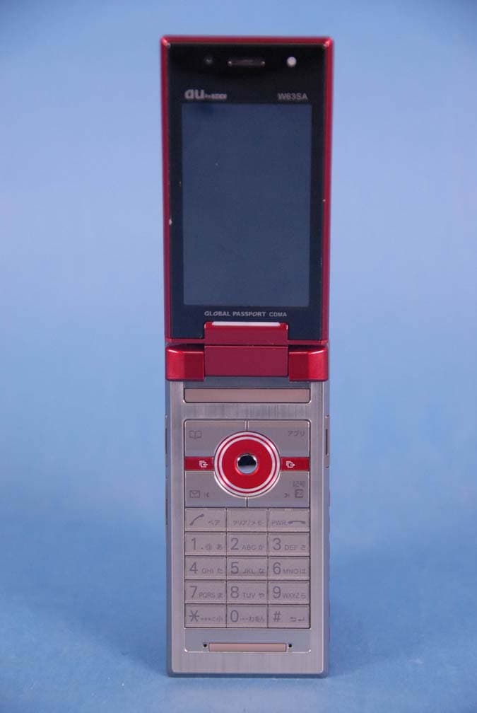
AEZW63SA
Mar 30, 2008Cellular CDMA Phone with Bluetooth
Equipment Class
TNE - Licensed Non-Broadcast Transmitter Held to Ear
AEZSCP-3800
Mar 09, 2008Cellular/ PCS CDMA Phone with Bluetooth
Equipment Class
JBP - Part 15 Class B Computing Device Peripheral
AEZSCP-25H
Sep 12, 2007Cellular/ PCS CDMA Phone with Bluetooth
Equipment Class
DSS - Part 15 Spread Spectrum Transmitter
AEZCPE-400-2C0
Jun 14, 2007W-CDMA subscriber terminal
Equipment Class
TNB - Licensed Non-Broadcast Station Transmitter
AEZNVM-4070
Jun 04, 2007PND (Personal Navigation Device)
Equipment Class
DXT - Part 15 Low Power Transceiver, Rx Verified