AFJ271420Marine Radar
ICOM Incorporated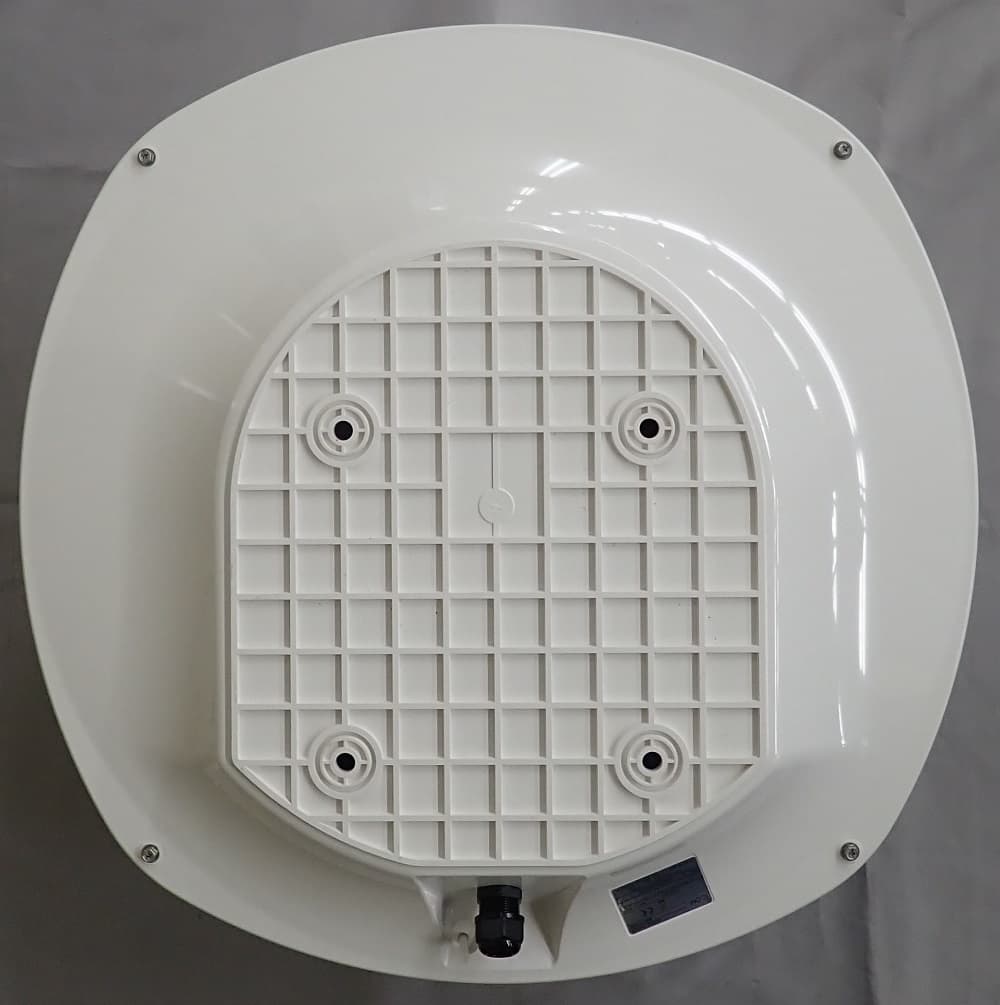
Click to zoom
Application Details
- Equipment Class
- MRD - Marine Radar
- Date of Grant
- Jan 06, 2021
- Application Purpose
- Original Equipment
- Date of Application
- Jan 06, 2021
- Equipment Note
- Marine Radar
- Frequency Range
- 9200.00000000 - 9500.00000000
- Company
- ICOM Incorporated
- Country
- Japan
Documents & Files
Document Text
Text extracted from the exhibit documents filed with the FCC. Open a document above to read the original.
Users Manual
MR-1010R™ MARINE RADAR INSTRUCTION MANUAL MR-1010RII / Page 13-1 i SUPPLIED ACCESSORIES SYSTEM COMPONENTS MODEL NAMEDISPLAY UNITSCANNER UNIT MR-1010RII10.4-inch Color LCDEX-2714 (Radome type) z Scanner unit (EX-2714) Quantity 1. System cable (15 m) ..........................................1 2. Installation bolts (M10×50) .................................4 3. Installation bolts (M10×25) .................................4 4. Installation nuts (M10) ........................................4 5. Flat washers (M10) .............................................4 6. Spring washers (M10) ........................................4 z10.4-inch Color LCD display unit Quantity 1. NMEA connector (PLT-167-P-R) ........................1 2. NMEA connector (PLT-168-P-R) .........................1 3. Spare fuse (FGB 15 A, for 12 V DC) ..................1 4. Spare fuse (FGB 5 A, for 24 V DC) .....................1 5. DC power cable ..................................................1 6. Mounting bracket ................................................1 7. Mounting knob bolts ...........................................2 8. Installation bolts (M6×30) ...................................5 9. Installation nuts (M6) ..........................................5 10. Spring washers (M6) ........................................10 11. Flat washers (M6) .............................................10 12. Ferrite EMI filter ...................................................1 LSome accessories are not supplied, depending on the radar version. DISPOSAL The crossed-out wheeled-bin symbol on your product, literature, or packaging reminds you that in the European Union, all electrical and electronic products, batteries, and accumulators (rechargeable batteries) must be taken to designated collection locations at the end of their working life. Do not dispose of these products as unsorted municipal waste. Dispose of them according to the laws in your area. ABOUT CE AND DOC Hereby, Icom Inc. declares that the versions of MR-1010RII which have the “CE” symbol on the product, comply with the essential requirements of the Radio Equipment Directive, 2014/53/EU, and the restriction of the use of certain hazardous substances in electrical and electronic equipment Directive, 2011/65/EU. The full text of the EU declaration of conformity is available at the following internet address: https://www.icomjapan.com/support/ MR-1010RII / Page 13-2 ii Thank you for choosing this Icom product. The MR-1010RII marine radar is designed and built with Icom's state of the art technology and craftsmanship. With proper care, this product should provide you with years of trouble-free operation. IMPORTANT READ ALL INSTRUCTIONS carefully and completely before using the radar. SAVE THIS INSTRUCTION MANUAL— This manual contains important safety and operating instructions for the MR-1010RII. FEATURES The radar is "Made in Japan." It has powerful transmitting power for long range detection, a 10.4-inch wider view angle color display, simplified ARPA to detect up to 5 targets, and other advanced features. EXPLICIT DEFINITIONS WORDDEFINITION R DANGER! Personal death, serious injury or an explosion may occur. R WARNING! Personal injury, fire hazard, or electric shock may occur. CAUTIONEquipment damage may occur. NOTE Recommended for optimum use. No risk of personal injury, fire or electric shock. BE CAREFUL! SART signals may not be detected and displayed on the screen, depending on the SEA, RAIN or IR settings. Make the settings below to detect the SART signals on the screen. 1. Set the screen range to between 6 NM and 12 NM with [+/–]. (pp. 1, 7) 2. Set t he [GAIN] as high as possible. (pp. 2, 9) 3. Set [SEA] to minimum. (pp. 2, 9) 4. Set [ RAIN] to minimum. (pp. 2, 9) 5. Tu rn OFF the Interference rejection (IR) function. (p. 10) 6. Tu rn OFF the Echo Stretch function. ( p. 11) Icom, Icom Inc. and the Icom logo are registered trademarks of Icom Incorporated (Japan) in Japan, the United States, the United Kingdom, Germany, France, Spain, Russia, Australia, New Zealand, and/ or other countries. All other products or brands are registered trademarks or trademarks of their respective holders. The MR-1010RII is a supplemental aid to navigation and is not intended to be a substitute for accurate and current nautical charts. Icom is not responsible for the destruction, damage to, or performance of any Icom or non-Icom equipment, if the malfunction is because of: • Force majeure, including, but not limited to, fires, earthquakes, storms, floods, lightning, other natural disasters, disturbances, riots, war, or radioactive contamination. • The use of Icom marine radar with any equipment that is not manufactured or approved by Icom. MR-1010RII / Page 13-3 iii For Display unit: RWARNING! NEVER let metal, wire or other objects contact the inside of the display unit, or make incorrect contact with connectors on the rear panel. This could cause an electric shock or damage the display unit. RWARNING! NEVER apply AC voltage to the DC connector of the display unit. This could cause a fire or damage the display unit. RWARNING! NEVER apply more than 42 V DC to the DC connector of the display unit. This could cause a fire or damage the display unit. RWARNING! NEVER touch or operate the display unit with wet hands. This could cause an electric shock or damage the display unit. RWARNING! NEVER open the display unit. There are no user adjustment points. This could cause an electric shock and incorrect reassembly may cause a fire hazard. RWARNING! NEVER operate the radar during a lightning storm. It may result in an electric shock, cause a fire or damage the display unit. Always disconnect the power source and scanner unit before a storm. RWARNING! NEVER reverse the DC power cable polarity. This could cause a fire or damage the display unit. RWARNING! NEVER remove the fuse holder on the DC power cable. Excessive current caused by a short could cause a fire or damage the display unit. C…
Text truncated - open the document above for the full version.
Cover Letter(s)
0 ICOM To Whom It May Concern Subject: Applicant: Product: Model: FCC ID: Dear Sir/Madam, Authority to Act as an Agent lcom Incorporated Marine Rader MR-1010RII AFJ271420 lcom Inc. 1-6-19.Kamikuratsukuri,Hirano-ku.Osaka Japan. Phone: +81 6 6793 8424 Fax: +81 6 6793 3336 e-mail: [email protected] URL: http://www.icom.co.jp/Wor1d Date: October 27, 2020 We, the undersigned, hereby authorize Compliance Testing, LLC to act on our behalf in all matters relating to application for equipment authorization, including the signing of all documents relating to these matters. We also hereby certify that no party to the application authorized hereunder is subject to the denial of benefits, including FCC benefits, pursuant to Section 5301 of the Anti-Drug Abuse Act of 1988, 21 U.S.C. 853(a). Best regards lcom Incorporated Atsushi Tomiyama General Manager of Quality Assurance Department
Cover Letter(s)
0 ICOM To Whom It May Concern lcom Inc. 1-6-19.Kamikuratsukuri,Hirano-ku,Osaka Japan. Phone. +81 6 6793 8424 Fax +81 6 6793 3336 e-mail: [email protected] URL· http://www.icom.eo.jp/wor1d Date: October 27, 2020 Subject: Applicant: Confidentiality and Short-Term Confidentiality Letter FCC ID: lcom Incorporated AFJ271420 Dear Sir/Madam: The applicant would like to request the following documents submitted with this application for certification be withheld from public disclosure as per Section 0.457 & 0.459 of FCC Rules. Confidential 1. Operational Description 2. Block Diagram 3. Schematics 4. Parts Li st Short-Term Confidential for 120 days 6. External Photos 7. Internal Photos 8. Users Manual The above materials contain trade secrets and proprietary information not customarily released to the public. The public disclosure of these materials may be harmful to the applicant and provide unjustified benefits to its competitors. The applicant understands that pursuant to Section 0.457 of the Rules, disclosure of this application and all accompanying documentation shall not be made. Regards lcom Incorporated Atsushi Tomiyama General Manager of Quality Assurance Department
Cover Letter(s)
For USA Only Supplier’s Declaration of Conformity 47 CFR § 2.1077 Compliance Information Unique Identifier: Trade Name : ICOM Model Name: : MR-1010RII Responsible party: Company name : Icom America Inc. Address : 12421 Willows Road NE Kirkland, WA 98034 U.S. Contact Information: 800-USA-ICOM (800-872-4266) Monday - Friday 7AM to 5PM PST FCC Compliance Statement: This device complies with Part 15 of the FCC Rules. Operation is subject to the following two conditions: (1) This device may not cause harmful interference, and (2) this device must accept any interference received, including interference that may cause undesired operation.
ID Label/Location Info
MR-1010RII / Page 4-1 4. Identification of Equipment ID Label Part15 Label Label Location ID Label Part15 Label 44mm 20mm
Operational Description
MR-1010RII / Page 3-1 3. General information Manufacture :Icom Inc. Model Name :MR-1010RII Serial No. :0000205 Assignable Frequency :9300MHz - 9500MHz Center Frequency :9410MHz Type of Emission :P0N Peak Output Power :4kW Pulse Characteristics : PRF Pulse Width Guard Band PRF Pulse Width Guard Band 0.125n m 0.25nm 0.5nm 0.75nm 1nm 1.5nm 250ns 6.00MHz 2n m 250ns 6.00MHz 350ns 4.29MHz 3n m 350ns 4.29MHz 4n m 6nm 8nm 12nm 16nm 24nm 32nm 36nm Intermediate Frequency :60MHz IF Band width : 10MHz / 3MHz Manufacturer of AntennaIcom Inc. Type of Antenna :Slotted Waveguide Array Length of Antenna :600m m Horizontal Beam Width :4° Vertical Beam Width :22° Gain of Antenna :25dBi Typical Power Supply :DC 12 / 24V This report was prepared by ICOM INCORPORATED Test performed by 1.67MHz 720Hz900ns1.67MHz Range Antenna Rotation Short PulseLong Pulse 36rpm2160Hz 80ns18.75MHz 2160Hz 80ns18.75MHz 24rpm 1440Hz 1440Hz 720Hz900ns MR-1010RII / Page 4-2 Versions of Software or Firmware
Test Report
P20a0013_FCC_ Part 80_Rev 1.0 Page 1 of 18 Test Report Prepared for: Icom Incorporated Model: MR-1010RII Description: Marine Radar Serial Number: 00000205 FCC ID: AFJ271420 ISED ID: 202D-271410 To FCC Part 80 RSS-238 Issue 1 (July 2013) Date of Issue: December 8, 2020 On the behalf of the applicant: Icom Incorporated 1-1-32 Kamiminami Hirano-ku Osaka 547-0003 Japan Attention of: Atsushi Tomiyama, General Manager of QA Department Ph: +81 6 6793 8424 E-Mail: [email protected] Prepared by Compliance Testing, LLC 1724 S. Nevada Way Mesa, AZ 85204 (480) 926-3100 phone / (480) 926-3598 fax www.compliancetesting.com Project No: p20a0013 Greg Corbin Project Test Engineer This report may not be reproduced, except in full, without written permission from Compliance Testing. All results contained herein relate only to the sample tested. P20a0013_FCC_ Part 80_Rev 1.0 Page 2 of 18 Test Report Revision History Revision Date Revised By Reason for Revision 1.0 December 8, 2020 Greg Corbin Original Document P20a0013_FCC_ Part 80_Rev 1.0 Page 3 of 18 Table of Contents Description Page Standard Test Conditions Engineering Practices ................................................................................................................... 5 Test Results Summary ............................................................................................................................................................ 6 Statements of conformity ........................................................................................................................................................ 6 Modulation Requirements ....................................................................................................................................................... 7 Output Power (Conducted) ..................................................................................................................................................... 8 Conducted Spurious Emissions .............................................................................................................................................. 9 Radiated Spurious Emissions ................................................................................................................................................. 11 Emission Mask ...................................................................................................................................................................... 13 Occupied Bandwidth ............................................................................................................................................................. 14 Frequency Stability (Temperature Variation) ........................................................................................................................ 15 Frequency Stability (Voltage Variation) ................................................................................................................................. 17 Test Equipment Utilized ........................................................................................................................................................ 18 P20a0013_FCC_ Part 80_Rev 1.0 Page 4 of 18 ANAB Compliance Testing, LLC, has been accredited in accordance with the recognized International Standard ISO/IEC 17025:2017. This accreditation demonstrates technical competence for a defined scope and the operation of a laboratory quality management system (refer to the joint ISO-ILAC-IAF Communiqué dated January 2009). The tests results contained within this test report all fall within our scope of accreditation, unless noted below. Please refer to http://www.compliancetesting.com/labscope.html for current scope of accreditation. FCC Site Reg. #349717 IC Site Reg. #2044A-2 Non-accredited tests contained in this report: N/A P20a0013_FCC_ Part 80_Rev 1.0 Page 5 of 18 Standard Test Conditions Engineering Practices Except as noted herein, the following conditions and procedures were observed during the testing: All tests and measurement data shown were performed in accordance with FCC Rules and Regulations, Volume II; Part 2, Sub-part J, Sections 2.947, 2.1033(c), 2.1041, 2.1046, 2.1047, 2.1051, 2.1053, 2.1055, 2.1057 and the following individual Parts: FCC Part 80, ANSI C63.26-2015, and ISED RSS-238, RSS-GEN. Measurement results, unless otherwise noted, are worst-case measurements. Environmental Conditions Temperature (ºC) Humidity (%) Pressure (mbar) 17.9 – 23.9 26.0 – 35.3 961.1 – 981 EUT Description Model: MR-1010RII Description: Marine Radar Serial Number: 00000120 PMN: MR1010RII HVIN: 271410-01 UPN: 271410 Additional Information The EUT is a 4kW Marine Radar operating at 9415 MHz. The radar operates from 10.2 – 42 volts DC. There is a 10 inch color TFT display that is used to control the radar and display the radar images. The RF output going to the antenna port is WR90 waveguide. Type of emission = PON The EUT has measurement ranges from 1/8, 1/4,1/2, 3/4, 1, 1.5, 2. 3. 4. 6, 8, 12, 16, 24, 32, 36 NM (NM = nautical mile) The test results were recorded for 1/8, 3, and 36 NM. Refer to Table 1 for pulse width and repetition rates for 1/8, 3, 36 NM. Table 1 – Pulse Width/repetition rate vs distance Nautical Miles Measured PW and PRR Pulse Width (ns) PRR PRF (us) (Hz) 1/8 80 462.96 2160 3 350 694.44 1440 36 900 1388.89 720 The manufacturer supplied the following antenna information. Type Gain Side Lobe Back Lobe Size (mm) dBi dB dB Width Height Slotted Waveguide Array 25 -22 N/A 553 95.2 EUT Operation during Tests The EUT was tested at 18 vdc under normal operation. There was a waveguide coupler and 30 dB attenuator connected to the output for all tests unless otherwise noted for individual tests. P20a0013_FCC_ Part 80_Rev 1.0 Page 6 of 18 Test Results Summary Specification Test Name Pass, Fail, N/A Comments FCC ISED 2.1047 80.213(g) RSS-238 Section 3.2 Modulation Requirements Pass 2.1046 80.215 (a)…
Text truncated - open the document above for the full version.
Test Report
P20a0013_FCC_Part 1.1310_Rev 1.0 Page 1 of 5 Test Report Prepared for: Icom Incorporated Model: MR-1010RII Description: Marine Radar Serial Number: 00000205 FCC ID: AFJ271420 To FCC Part 1.1310 Date of Issue: December 8, 2020 On the behalf of the applicant: Icom Incorporated 1-1-32 Kamiminami Hirano-ku Osaka 547-0003 Japan Attention of: Atsushi Tomiyama, General Manager of QA Department Ph: +81 6 6793 8424 E-Mail: [email protected] Prepared By Compliance Testing, LLC 1724 S. Nevada Way Mesa, AZ 85204 (480) 926-3100 phone / (480) 926-3598 fax www.compliancetesting.com Project No: p20a0013 Greg Corbin Project Test Engineer This report may not be reproduced, except in full, without written permission from Compliance Testing All results contained herein relate only to the sample tested P20a0013_FCC_Part 1.1310_Rev 1.0 Page 2 of 5 Test Report Revision History Revision Date Revised By Reason for Revision 1.0 December 8,2020 Greg Corbin Original Document P20a0013_FCC_Part 1.1310_Rev 1.0 Page 3 of 5 ANAB Compliance Testing, LLC, has been accredited in accordance with the recognized International Standard ISO/IEC 17025:2017. This accreditation demonstrates technical competence for a defined scope and the operation of a laboratory quality management system (refer to the joint ISO-ILAC-IAF Communiqué dated January 2009). The tests results contained within this test report all fall within our scope of accreditation, unless noted below. Please refer to http://www.compliancetesting.com/labscope.html for current scope of accreditation. FCC Site Reg. #349717 IC Site Reg. #2044A-2 Non-accredited tests contained in this report: N/A EUT Description Model: MR1010-RII Description: Marine Radar Serial Number: 00000120 Additional Information: The EUT is a 4kW Radome Scanner Marine Radar operating at 9.4 GHz. The radar operates from 10.2 – 42 volts DC. There is a 10 inch color TFT display that is used to control the radar and display the radar images. The RF output going to the antenna port is WR90 waveguide. Antenna gain = 25 dBi Due to the wide bandwidth (10 – 27 MHz, dependent on PW and PRR) of the radar signal, the channel power was measured using the channel power tool on the spectrum analyzer. The channel power was measured for 3 combinations of PW and PRR and the combination with the highest output was used to calculate the RF exposure. P20a0013_FCC_Part 1.1310_Rev 1.0 Page 4 of 5 MPE Evaluation This is a mobile device used in Uncontrolled Exposure environment. Limits Uncontrolled Exposure 47 CFR 1.1310 Table 1, (B) 0.3-1.234 MHz: Limit [mW/cm²] = 100 1.34-30 MHz: Limit [mW/cm²] = (180/f²) 30-300 MHz: Limit [mW/cm²] = 0.2 300-1500 MHz: Limit [mW/cm²] = f/1500 1500-100,000 MHz Limit [mW/cm²] = 1.0 Test Data Test Frequency, MHz 9415 Power, Conducted, mW (P) 3605.8 Antenna Gain Isotropic 25 dBi Antenna Gain Numeric (G) 316.23 Antenna Type Slotted Waveguide Array Distance (R) 20 cm 푆푆= 푃푃∗퐺퐺 4휋휋푟푟 2 Power Density (S) mw/cm 2 226.85 mw/cm 2 Power Density (S) = 226.85 mw/cm 2 Limit = (from above table) = 1.0 mw/cm 2 The power density at 226.85 mw/cm 2 is over the 1.0 mw/cm 2 limit so the minimum safe distance was calculated. P20a0013_FCC_Part 1.1310_Rev 1.0 Page 5 of 5 Minimum Safe Distance Evaluation This is a mobile device used in Uncontrolled Exposure environment. Limits Uncontrolled Exposure 47 CFR 1.1310 Table 1, (B) 0.3-1.234 MHz: Limit [mW/cm²] = 100 1.34-30 MHz: Limit [mW/cm²] = (180/f²) 30-300 MHz: Limit [mW/cm²] = 0.2 300-1500 MHz: Limit [mW/cm²] = f/1500 1500-100,000 MHz Limit [mW/cm²] = 1.0 Test Data Test Frequency, MHz 9415 Power, Conducted, mW (P) 3605.8 Antenna Gain Isotropic 25 dBi Antenna Gain Numeric (G) 316.23 Antenna Type Slotted Waveguide Array Limit (L) 20 cm R=√(PG/4πL) Distance (R) cm Power mW (P) Numeric Gain (G) Limit (L) 301.3 3605.8 316.23 1.0 The minimum safe distance is 301.3 cm with a 25 dBi gain antenna. END OF TEST REPORT
Test Report
P20a0013_Annex A _ Rev 1.0 Page 1 of 4 Annex A Modulation P20a0013_Annex A _ Rev 1.0 Page 2 of 4 Modulation 0.125 NM_PRR 458.9 us_p20a0013 Modulation 0.125 NM_PW 180 ns_p20a0013 P20a0013_Annex A _ Rev 1.0 Page 3 of 4 Modulation 3 NM_PRR 690.2 us_p20a0013 Modulation 3 NM_PW 460 ns_p20a0013 P20a0013_Annex A _ Rev 1.0 Page 4 of 4 Modulation 36 NM_PRR 1387 us_p20a0013 Modulation 36 NM_PW 1040 us_p20a0013
Test Report
p20a0013_Annex B _ Rev 1.0 Page 1 of 10 Annex B Conducted Spurious p20a0013_Annex B _ Rev 1.0 Page 2 of 10 Conducted Spurious_0.125 NM_1 - 12.4 GHz_p20a0013 Conducted Spurious_0.125 NM_12.4 - 18 GHz_p20a0013 p20a0013_Annex B _ Rev 1.0 Page 3 of 10 Conducted Spurious_0.125 NM_18 - 26.5 GHz_p20a0013 Conducted Spurious_0.125 NM_26.5 - 40 GHz_3rd Harmonic_p20a0013 p20a0013_Annex B _ Rev 1.0 Page 4 of 10 Conducted Spurious_0.125 NM_26.5 - 40 GHz_p20a0013 Conducted Spurious_0.125 NM_30 - 1000 MHz_p20a0013 p20a0013_Annex B _ Rev 1.0 Page 5 of 10 Conducted Spurious_3 NM_1 - 12.4 GHz_p20a0013 Conducted Spurious_3 NM_12.4 - 18 GHz_p20a0013 p20a0013_Annex B _ Rev 1.0 Page 6 of 10 Conducted Spurious_3 NM_18 - 26.5 GHz_p20a0013 Conducted Spurious_3 NM_26.5 - 40 GHz_3rd Harmonic_p20a0013 p20a0013_Annex B _ Rev 1.0 Page 7 of 10 Conducted Spurious_3 NM_26.5 - 40 GHz_p20a0013 Conducted Spurious_3 NM_30 - 1000 MHz_p20a0013 p20a0013_Annex B _ Rev 1.0 Page 8 of 10 Conducted Spurious_36 NM_1 - 12.4 GHz_p20a0013 Conducted Spurious_36 NM_12.4 - 18 GHz_p20a0013 p20a0013_Annex B _ Rev 1.0 Page 9 of 10 Conducted Spurious_36 NM_18 - 26.5 GHz_p20a0013 Conducted Spurious_36 NM_26.5 - 40 GHz_3rd Harmonic_p20a0013 p20a0013_Annex B _ Rev 1.0 Page 10 of 10 Conducted Spurious_36 NM_26.5 - 40 GHz_p20a0013 Conducted Spurious_36 NM_30 - 1000 MHz_p20a0013
Test Report
P20a0013_Annex C_ Rev 1.0 Page 1 of 10 Annex C Radiated Spurious Emission P20a0013_Annex C_ Rev 1.0 Page 2 of 10 Radiated Emission_1 - 18 GHz_0.125 NM_p20a0013 Radiated Emission_1 - 18 GHz_3 NM_p20a0013 P20a0013_Annex C_ Rev 1.0 Page 3 of 10 Radiated Emission_1 - 18 GHz_36 NM_p20a0013 Radiated Emission_18 - 26.5 GHz_0.125 NM_p20a0013_Peak Det P20a0013_Annex C_ Rev 1.0 Page 4 of 10 Radiated Emission_18 - 26.5 GHz_3 NM_p20a0013_Avg Det Radiated Emission_18 - 26.5 GHz_3 NM_p20a0013_Peak det P20a0013_Annex C_ Rev 1.0 Page 5 of 10 Radiated Emission_18 - 26.5 GHz_36 NM_p20a0013_Avg Det Radiated Emission_18 - 26.5 GHz_36 NM_p20a0013_Peak Det P20a0013_Annex C_ Rev 1.0 Page 6 of 10 Radiated Emission_26.5 - 40 GHz_0.125 NM_p20a0013_Peak Det Radiated Emission_26.5 - 40 GHz_28240.4 MHz_36 NM_p20a0013 P20a0013_Annex C_ Rev 1.0 Page 7 of 10 Radiated Emission_26.5 - 40 GHz_28245 MHz_0.125 NM_p20a0013 Radiated Emission_26.5 - 40 GHz_28245 MHz_3 NM_p20a0013 P20a0013_Annex C_ Rev 1.0 Page 8 of 10 Radiated Emission_26.5 - 40 GHz_3 NM_p20a0013_Peak Det Radiated Emission_26.5 - 40 GHz_36 NM_p20a0013_Peak Det P20a0013_Annex C_ Rev 1.0 Page 9 of 10 Radiated Emission_30 MHz - 1 GHz_0.125 NM_p20a0013 Radiated Emission_30 MHz - 1 GHz_3 NM_p20a0013 P20a0013_Annex C_ Rev 1.0 Page 10 of 10 Radiated Emission_30 MHz - 1 GHz_36 NM_p20a0013
Test Report
P20a0013_Annex D_ Rev 1.0 Page 1 of 3 Annex D Emission Mask P20a0013_Annex D_ Rev 1.0 Page 2 of 3 Emission Mask_0.125 NM_p20a0013 Emission Mask_3.0 NM_p20a0013 P20a0013_Annex D_ Rev 1.0 Page 3 of 3 Emission Mask_36 NM_p20a0013
Test Report
P20a0013_Annex E_ Rev 1.0 Page 1 of 4 Annex E Occupied Bandwidth P20a0013_Annex E_ Rev 1.0 Page 2 of 4 OCC BW_-40 dB_0.125 NM_p20a0013 OCC BW_-40 dB_3 NM_p20a0013 P20a0013_Annex E_ Rev 1.0 Page 3 of 4 OCC BW_-40 dB_36 NM_p20a0013 OCC BW_99%_0.125 NM_p20a0013 P20a0013_Annex E_ Rev 1.0 Page 4 of 4 OCC BW_99%_3 NM_p20a0013 OCC BW_99%_36 NM_p20a0013
Test Setup Photos
Test Setup Photos FCC ID: AFJ271420 ISED ID: 202D-271410 Conducted Emissions Conducted Emissions Test Setup Photos FCC ID: AFJ271420 ISED ID: 202D-271410 Radiated Emissions – below 1 GHz Radiated Emissions – above 1 GHz
Contact Information
Applicant
Atsushi Tomiyama(General Manager)
Technical Contact
ICOM IncMunekazu Takeda
[email protected]+81667938424
1-6-19, Kamikurazukuri, Hirano-ku · Osaka · Japan
Non-Technical Contact
ICOM Inc.Munekazu Takeda
[email protected]+81667938424
Test Firm
Compliance Testing, LLCMichael Schafer
[email protected]480-926-3100
Technical Specifications
| # | Rule Parts | Frequency Range | Power Output | Emission | Tolerance |
|---|---|---|---|---|---|
| 1 | 80 | 9.20 GHz - 9.50 GHz | 3.606 W | 44M4P0N | 10.8000000000 % |
Other Applications from ICOM Incorporated

AFJ460100
Aug 31, 2026VHF DSC Marine Radio
Equipment Class
TNB - Licensed Non-Broadcast Station Transmitter
AFJ453700
Jul 23, 2026Mobile Transceiver
Equipment Class
DTS - Digital Transmission System
AFJ452000
Jun 02, 2026VHF DIGITAL TRANSCEIVER
Equipment Class
TNF - Licensed Non-Broadcast Transmitter Held to Face
AFJ452100
May 12, 2026UHF DIGITAL TRANSCEIVER
Equipment Class
TNF - Licensed Non-Broadcast Transmitter Held to Face
AFJ444500
Sep 12, 2024Scanning Receiver
Equipment Class
CSR - Scanning Receiver