AFJ284400Scanning Receiver
ICOM Incorporated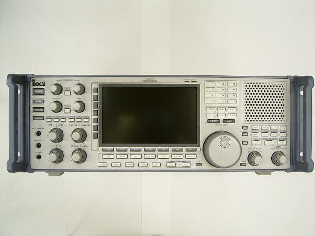
Click to zoom
Application Details
- Equipment Class
- CSR - Scanning Receiver
- Date of Grant
- Feb 26, 2007
- Application Purpose
- Original Equipment
- Date of Application
- Feb 15, 2007
- Equipment Note
- Scanning Receiver
- Frequency Range
- 896.00000000 - 960.00000000
- Company
- ICOM Incorporated
- Country
- Japan
Documents & Files
Document Text
Text extracted from the exhibit documents filed with the FCC. Open a document above to read the original.
Users Manual
COMMUNICATIONS RECEIVER iR9500 Instruction Manual A-6553H-1EX Printed in Japan © 2007 Icom Inc. i FOREWORD Thank you for making the IC-R9500 your radio of choice. We hope you agree with Icom’s philosophy of “technology first.” Many hours of research and development went into the design of your IC-R9500. DFEATURES ❍Ultimate receiver performance: 110 dB wide dynamic range and third-order intercept (IP3) of +40 dBm (HF bands only) ❍7-inch wide color TFT LCD ❍Built-in Baudot FSK demodulator ❍High resolution spectrum scope— center frequency and fix frequency modes, plus mini-scope displays IMPORTANT READ THIS INSTRUCTION MANUAL CAREFULLYbefore at- tempting to operate the receiver. SAVE THIS INSTRUCTION MANUAL.This manual contains im- portant safety and operating instructions for the IC-R9500. EXPLICIT DEFINITIONS TRADEMARKS Icom, Icom Inc. and the logo are registered trademarks of Icom Incorporated (Japan) in the United States, the United Kingdom, Germany, France, Spain, Russia and/or other countries. WORDDEFINITION R WARNING Personal injury, fire hazard or electric shock may occur. CAUTIONEquipment damage may occur. NOTE If disregarded, inconvenience only. No risk of person- al injury, fire or electric shock. ii PRECAUTIONS RWARNING! NEVER operate the receiver with a headset or other audio accessories at high volume levels. Hearing experts advise against continuous high volume operation. If you experience a ringing in your ears, reduce the volume or discontinue use. RCAUTION! NEVER change the internal set- tings of the receiver. This may reduce receiver perfor- mance and/or damage to the receiver. The receiver warranty does not cover any problems caused by unauthorized internal adjustment. RCAUTION!The receiver weighs approx. 20 kg (44 lb). Always have two people available to carry, lift or turn over the receiver. RCAUTION!The line-voltage receptacle must be near the receiver and must be easily accessible. Avoid extension cords. RACHTUNG!Die Steckdose muß nabe bei diesem Gerät angebracht und zugänglich sein. RNEVERlet metal, wire or other objects protrude into the receiver or into connectors on the rear panel. This may result in an electric shock. RNEVERblock any cooling vents on the top, rear or bottom of the receiver. RNEVERexpose the receiver to rain, snow or any liquids. RNEVERinstall the receiver in a place without ad- equate ventilation. Heat dissipation may be reduced, and the receiver may be damaged. RNEVERoperate or touch the receiver with wet hands. This may result in an electric shock or damage to the receiver. DO NOTuse chemical agents such as benzine or al- cohol when cleaning the IC-R9500, as they can dam- age the receiver’s surfaces. AVOIDusing or storing the receiver in areas with tem- peratures below ±0°C (+32°F) or above +50°C (+122°F). AVOIDplacing the receiver in excessively dusty envi- ronments or in direct sunlight. AVOIDplacing the receiver against walls or putting anything on top of the receiver. This may overheat the receiver. Always place unit in a secure place to avoid inadver- tent use by children. The LCD display may have cosmetic imperfections that appear as small dark or light spots. This is not a mal- function or defect, but a normal characteristic of LCD displays. During maritime mobile operation, keep the receiver as far away as possible from the magnetic navigation compass to prevent erroneous indications. Turn [I/O] switch (on the rear panel) OFF and/or dis- connect the AC power cable from the AC outlet when you will not use the receiver for a long period of time. For U.S.A. only CAUTION:Changes or modifications to this device, not expressly approved by Icom Inc., could void your authority to operate this device under FCC regulations. ABOUT APCO PROJECT 25 This device made under license under one or more of the following US patents: #4,590,473, #4,636,791, #5,148,482, #5,185,796, #5,271,017, #5,377,229. The IMBE™ voice coding technology embodied in this product is protected by intellectual property rights including patent rights, copyrights and trade secrets of Digital Voice Systems, Inc. This voice coding Technology is licensed solely for use within this com- munications equipment. The user of this technology is explicitly prohibited from attempting to decompile, reverse engineer, or disassemble the object code, or in any other way convert the object code into a human-readable form. U.S. Pat. nos. #5,870,405, #5,826,222, #5,754,974, #5,701,390, #5,715,365, #5,649,050, #5,630,011, #5,581,656, #5,517,511, #5,491,772, #5,247,579, #5,226,084, #5,195,166. P25 digital mode is available when the optional UT-122 DIGITAL UNITis installed. qAC power cable* ....................................... 1 wCarrying handles .................................... 1 set eSpare fuse (FGB 1 A) ................................. 1 rSpare fuse FGB 4 A (100 V/120 V versions) ..................... 1 0234002MXP (230 V/240 V versions)............... 1 tRCA plugs ................................................ 4 yDC power plug .......................................... 1 u2-conductor 1 ⁄8wplugs ................................. 7 i3-conductor 1 ⁄8wplugs ................................. 1 o8 pin ACC plugs .......................................... 2 !0Screws for side plate † ................................. 4 !1Hiding screws for screw hole † ........................ 2 *May differ from that shown according to version † These screw are used when removing rack mounting han- dles iii SUPPLIED ACCESSORIES q o !0 !1 tyu i e w r (FH M4×16 mm) (FH M4×12 mm) (PH M4×8 mm) PH: Pan head FH: Flat head iv Section 1PANEL DESCRIPTION ■Front panel ........................................................................ 1-2 ■Rear panel ........................................................................ 1-8 ■LCD display ..................................................................... 1-10 ■Screen menu arrangement ................................................... 1-12 Section 2INSTALLATION AND…
Text truncated - open the document above for the full version.
Users Manual
4-19 4 RECEIVE MODES ■Digital squelch operation While in P25 mode operation, 2 types of digital squelch, NAC or Selective, are available. qSet the desired frequency and select P25 mode. wPush [D.SQL] to turn the digital squelch function ON. • “NAC” or “SEL”appears when the digital squelch func- tion is ON. ePush and hold [D.SQL] for 1 sec. to enter P25 digi- tal squelch set mode. rPush [F-1•Y] or [F-2•Z] to select the items, “NAC,” “TGID” or “Unit ID.” tPush [F-5•EDIT] to enter digital code programming. • A cursor appears and blinks. • Push [F-1•Ω] or [F-2•≈] for cursor movement. • Push [F-3•DEL] to delete the selected code. • Using the receiver’s keypad, [0]–[9], can also enter nu- merals. • Multifunction switch guide changes to the additional keys, [A]–[F], for hexadecimal input. yPush [F-5•SET] to input and set the code. • The cursor disappears. uPush [EXIT/SET] to return to the previous indica- tion. iWhen the received signal includes a matching code, squelch opens and the signal can be heard. • When the received signal’s code does not match, digital squelch does not open, however, the S-indicator shows signal strength. oTo open the digital squelch manually, push [MONI]. • The digital squelch opens temporarily while pushing and holding [MONI]. !0To cancel digital squelch, push [D.SQL] several times to clear the digital squelch. • “NAC” or “SEL” disappears and “OFF” appears. • Digital squelch set mode [EXIT/SET] [MONI][DIGITAL]Main dial[D.SQL] [F-1•Y] [F-2•Z] [F-5•EDIT] 5-1 RECEIVE FUNCTIONSSection5 ■Spectrum scope screen ...................................................... 5-2 DCenter mode .................................................................. 5-2 DFix mode ........................................................................ 5-3 DPeak marker function ...................................................... 5-4 DWide band-pass filter selection............................................. 5-5 DWide band scope function ................................................... 5-5 DMini scope screen indication ............................................. 5-6 DScope set mode ............................................................... 5-6 ■Preamplifier ........................................................................ 5-9 ■Attenuator ........................................................................ 5-9 ■AGC function ..................................................................... 5-10 DSelecting the preset value ................................................5-10 DAdjusting the AGC time constant .......................................5-10 DSetting the AGC time constant preset value ........................5-10 ■Twin PBT operation ............................................................ 5-11 ■IF filter selection ............................................................... 5-12 DIF filter selection ............................................................ 5-12 DFilter passband width setting ............................................. 5-12 DRoofing filter selection ...................................................... 5-13 DDSP filter shape ............................................................ 5-13 DFilter shape set mode ...................................................... 5-13 ■Noise blanker .................................................................. 5-15 DNB set mode .................................................................. 5-15 ■Noise reduction .................................................................. 5-16 ■Notch function .................................................................. 5-16 ■Autotune function ............................................................... 5-17 ■AFC function ..................................................................... 5-17 5-2 ■Spectrum scope screen This DSP-based spectrum scope allows you to display the conditions on the selected band, as well as relative strengths of signals. The IC-R9500 has two modes for the spectrum indication— one is center mode, and an- ther one is fixed mode. In addition, the IC-R9500 has a mini-scope screen to save screen space. D Center mode Displays signals around the set frequency within the selected span. The set frequency is always displayed at the center of the screen. qPush [EXIT/SET] several times to close a multi- function screen, if necessary. wPush [F-1•SCOPE] to select the scope screen. • The spectrum scope shows the peak level holding func- tion. Peak levels are displayed in the background of the current spectrum in a different color until the receive fre- quency changes. This can be deactivated and the wave- form color can be set in scope set mode. (p. 5-7) ePush [F-6•CENT/FIX] to select the center mode. • “” is displayed when center mode is selected. rPush [F-2•SPAN] once. • Multifunction switch guide changes to the span setting guide. tPush [SPAN+] or [SPAN–] several times to select the scope span. • ±2.5 k, ±5.0 k, ±10 k, ±25 k, ±50 k, ±100 k, ±250 k, ±500 k, ±1 M, ±2.5 M and ±5 MHz are available. yPush [F-3•BW/SPEED] once. • Multifunction switch guide changes to the resolution band width/speed setting guide. uPush [BW+] or [BW–] several times to select the resolution band width. • 0.2 k, 0.5 k, 1 k, 2 k, 5 k, 10 k and 20 kHz are available. iPush [SPEED–] or [SPEED+] several times to se- lect the sweep speed. oPush [F-4•ATT] several times to activate an attenu- ator or turn the attenuator OFF. • 10, 20 and 30 dB attenuators are available. !0Push [F-5•HOLD] to freeze the current spectrum waveform. • “” appears while the function is in use. • The peak hold function can be deactivated in scope set mode. !1Push [EXIT/SET] to exit the scope screen. NOTE:If a strong signal is received, a ghost wave- form may appear. Push [F-4•ATT] several times to activate the spectrum scope attenuator in this case. Spurious signal waveforms may be displayed if gen- erated in the internal scope circuit and do not indi- cate a receiver malfunction.…
Text truncated - open the document above for the full version.
Users Manual
11-1 SET MODESection11 ■Set mode description ......................................................... 11-2 DSet mode operation ......................................................... 11-2 DScreen arrangement ...................................................... 11-3 ■Level set mode .................................................................. 11-4 ■ACC set mode .................................................................. 11-7 ■Display set mode ............................................................... 11-8 ■Others set mode ............................................................... 11-10 ■CF card/USB-Memory set menu .......................................... 11-16 DCF/USB-Memory set screen arrangement ........................ 11-16 DLoad option set mode ................................................... 11-17 ■File saving ..................................................................... 11-18 ■File loading ..................................................................... 11-19 ■Changing the file name ...................................................... 11-20 ■File copying ..................................................................... 11-21 ■Deleting a file .................................................................. 11-22 ■Unmount an USB-Memory ................................................ 11-22 ■Formatting the CF card or USB-Memory .............................. 11-23 ■Display set (Video) mode ................................................... 11-24 ■LCD set mode .................................................................. 11-26 11-2 ■Set mode description Set mode is used for programming infrequently changed values or conditions of functions. The IC- R9500 has a level set mode, display set mode, timer set mode, accessory set mode, others set mode and CF/USB-Memory set mode. D Set mode operation qPush [EXIT/SET] several times to close a multi- function screen, if necessary. wPush [F-7•SET] to select set mode menu screen. • Pushing and holding [EXIT/SET] for 1 sec. also selects set mode menu screen. ePush [F-1•LEVEL], [F-2•ACC], [F-3•DISP], [F-4•TIME], [F-5•OTHERS] or [F-7•CF/USB] to enter the desired set mode. rFor level, accessory, display and others set mode, push [F-7•WIDE] to toggle wide and normal screen. tPush [F-1•Y] or [F-2•Z] to select the desired item, then rotate main dial to adjust/select the desired value or condition. • Pushing [F-3•Ω≈] operation may be necessary for some items. yPush [EXIT/SET] twice to exit set mode. [EXIT/SET]Main dial [F-1•LEVEL] [F-2•ACC] [F-3•DISP] [F-5•OTHERS] [F-4•TIME] [F-7•CF/USB] 11 SET MODE 11-3 11 SET MODE D Screen arrangement • Set mode menu screen (p. 11-2) • Level set mode (p. 11-4) • ACC set mode (p. 11-7) • Time set mode (p. 10-2) • Display set mode (p. 11-8) • Miscellaneous (Others) set mode (p. 11-10) • CF/USB-Memory set menu (p. 11-16) 11-4 11 SET MODE ■Level set mode Sets the bass level of the receive audio in FM mode from –5 to +5. (default: 0) FMTone (Bass)0 Sets the treble level of the receive audio in FM mode from –5 to +5. (default: 0) FMTone (Treble)0 Sets the bass level of the receive audio in WFM mode from –5 to +5. (default: 0) WFM Tone (Bass)0 Sets the treble level of the receive audio in WFM mode from –5 to +5. (default: 0) WFM Tone (Treble)0 Sets the bass level of the receive audio in AM mode from –5 to +5. (default: 0) AMTone (Bass)0 Sets the treble level of the receive audio in AM mode from –5 to +5. (default: 0) AMTone (Treble)0 Sets the bass level of the receive audio in SSB mode from –5 to +5. (default: 0) SSB Tone (Bass)0 Sets the treble level of the receive audio in SSB mode from –5 to +5. (default: 0) SSB Tone (Treble)0 Sets the bass level of the receive audio in CW mode from –5 to +5. (default: 0) CWTone (Bass)0 Sets the treble level of the receive audio in CW mode from –5 to +5. (default: 0) CWTone (Treble)0 11-5 11 SET MODE ■Level set mode (continued) Sets the bass level of the receive audio in FSK mode from –5 to +5. (default: 0) FSK Tone (Bass)0 Sets the treble level of the receive audio in FSK mode from –5 to +5. (default: 0) FSK Tone (Treble)0 Sets the de-emphasis circuit ON and OFF when the 15 kHz width filter is used in FM mode. (default: ON) (FM 15k)ON Sets the de-emphasis circuit ON and OFF when the 7 kHz width filter is used in FM mode. (default: ON) (FM 7k)ON Sets the AF high cut filter circuit ON and OFF when the 50 kHz width filter is used in FM mode. (default: OFF) AF High Cut (FM 50k)OFF Sets the AF high cut filter circuit ON and OFF when the 15 kHz width filter is used in FM mode. (default: ON) (FM 15k)ON Sets the AF high cut filter circuit ON and OFF when the 7 kHz width filter is used in FM mode. (default: ON) (FM 7k)ON Sets the AF high cut filter circuit ON and OFF in WFM mode. (default: OFF) (WFM)OFF De-emphasis is the use of an amplitude-frequency characteristic complimentary to the one used for pre- emphasis prior to transmission. Sets the de-emphasis circuit ON and OFF when the 50 kHz width filter is used in FM mode. (default: OFF) De-Emphasis (FM 50k)OFF 11-6 11 SET MODE Turns the AF high cut filter circuit ON and OFF in SSB mode. (default: ON) (SSB)ON Turns the AF high cut filter circuit ON and OFF in CW mode. (default: ON) (CW)ON Turns the AF high cut filter circuit ON and OFF in FSK mode. (default: ON) (FSK)ON Turns the AF high cut filter circuit ON and OFF in P25 mode. (default: ON) (P25)ON ■Level set mode (continued) Sets the voice synthesizer audio output level from 0 to 100% in 1% steps. (default: 50%) Speech Level50 % Sets the key-touch beep output level from 0 to 100% in 1% steps. (default: 50%) Beep Level50 % Turns the key-touch beep output level limiting capa- bility from ON and OFF. (default: ON) Beep Level LimitON Sets the ratio for audio output level from the head- phone to the internal speaker from 0.60 to 1.40 range in 0.01 steps. (default: 1.00) Phones Level Ratio1.00 Turns the AF high cut filter circuit ON and OFF i…
Text truncated - open the document above for the full version.
Cover Letter(s)
February 8, 2007 AmericanTCB, Inc. 6731 Whittier Avenue, Suite C110 McLean, VA 22101 Subject: Certification Testing Application for Scanning Receiver tested in accordance with FCC CFR 47, Part 15, Subpart B - Scanning Receivers Operating in the frequency bands 0.005-3335 MHz (excluding cellular bands). Product: COMMUNICATION RECEIVER Model No.: IC-R9500 FCC ID: AFJ284400 Dear Sir/Madam As appointed agent for ICOM Incorporated, we would like to submit the application for FCC certification of the above product. Please review all files uploaded to AmericanTCB electronic filing site. If you have any queries, please do not hesitate to contact us. Yours truly, Tri Minh Luu, P. Eng., V.P., Engineering Encl UltraTech Group of Labs Ultratech’s Accreditations: 0685 31040/SIT C-1376 46390-2049 200093-0 SL2-IN-E-1119R 3000 Bristol Circle, Oakville, Ontario, Canada L6H 6G4 Tel.: (905) 829-1570 Fax.: (905) 829-8050 Website: www.ultratech-labs.com Email: [email protected]
Test Report
COMMUNICATION RECEIVER Model No.: IC-R9500 FCC ID: AFJ284400 Applicant: ICOM Incorporated 1-1-32, Kamiminami Hirano-ku, Osaka Japan, 547-003 Tested in Accordance With Federal Communications Commission (FCC) 47 CFR, Part 15, Subpart B Scanning Receivers operating in the Frequency Bands 0.005 - 3335 MHz (excluding cellular bands) UltraTech's File No.: ICOM-144_FCC15R This Test report is Issued under the Authority of Tri M. Luu, Professional Engineer, Vice President of Engineering UltraTech Group of Labs Date: February 8, 2007 Report Prepared by: Dharmajit Solanki Issued Date: February 8, 2007 Tested by: Wayne Wu, EMI/RFI Technician Test Dates: Jan. 25 to Feb 05, 2007 The results in this Test Report apply only to the sample(s) tested, and the sample tested is randomly selected. This report must not be used by the client to claim product endorsement by NVLAP or any agency of the US Government. UltraTech 3000 Bristol Circle, Oakville, Ontario, Canada, L6H 6G4 Tel.: (905) 829-1570 Fax.: (905) 829-8050 Website: www.ultratech-labs.com , Email: [email protected], Email: [email protected] 0685 31040/SIT C-1376 46390-2049 200093-0 SL2-IN-E-1119R FCC PART 15, SUBPART B, SCANNING RECEIVERS Page 2 Communication Receiver, Model IC-R9500 FCC ID: AFJ284400 ULTRATECH GROUP OF LABS File #: ICOM-144_FCC15R 3000 Bristol Circle, Oakville, Ontario, Canada L6H 6G4 February 8, 2007 Tel.: 905-829-1570, Fax. : 905-829-8050 All test results contained in this engineering test report are traceable to National Institute of Standards and Technology (NIST) TABLE OF CONTENTS EXHIBIT 1. INTRODUCTION ...................................................................................................................................... 3 1.1. SCOPE...................................................................................................................................................................... 3 1.2. RELATED SUBMITTAL(S)/GRANT(S) ............................................................................................................... 3 1.3. NORMATIVE REFERENCES ................................................................................................................................ 3 EXHIBIT 2. PERFORMANCE ASSESSMENT ........................................................................................................... 4 2.1. CLIENT INFORMATION ....................................................................................................................................... 4 2.2. EQUIPMENT UNDER TEST (EUT) INFORMATION .........................................................................................4 2.3. EUT’S TECHNICAL SPECIFICATIONS .............................................................................................................. 5 2.4. ANCILLARY EQUIPMENT ................................................................................................................................... 5 2.5. BLOCK DIAGRAM OF TEST SETUP................................................................................................................... 6 EXHIBIT 3. EUT OPERATING CONDITIONS AND CONFIGURATIONS DURING TESTS ............................ 7 3.1. CLIMATE TEST CONDITIONS ............................................................................................................................ 7 3.2. OPERATIONAL TEST CONDITIONS & ARRANGEMENT FOR TEST SIGNALS.......................................... 7 EXHIBIT 4. SUMMARY OF TEST RESULTS ............................................................................................................ 8 4.1. LOCATION OF TESTS........................................................................................................................................... 8 4.2. APPLICABILITY & SUMMARY OF EMC EMISSION TEST RESULTS .......................................................... 8 4.3. MODIFICATIONS REQUIRED FOR COMPLIANCE..........................................................................................8 EXHIBIT 5. MEASUREMENTS, EXAMINATIONS & TEST DATA FOR EMC EMISSIONS............................ 9 5.1. TEST PROCEDURES.............................................................................................................................................. 9 5.2. MEASUREMENT UNCERTAINTIES ................................................................................................................... 9 5.3. MEASUREMENT EQUIPMENT USED ................................................................................................................ 9 5.4. ESSENTIAL/PRIMARY FUNCTIONS AS DECLARED BY THE MANUFACTURER..................................... 9 5.5. AC POWER LINE CONDUCTED EMISSIONS [47 CFR 15.107(A)] ................................................................ 10 5.6. RECEIVER ANTENNA POWER SPURIOUS/HARMONIC CONDUCTED EMISSIONS [47 CFR 15.111(A)] 13 5.7. RECEIVER SPURIOUS/HARMONIC RADIATED EMISSIONS [47 CFR 15.109(A)] .................................... 31 5.8. RADIATED EMISSIONS FROM CLASS B UNINTENTIONAL RADIATION (DIGITAL DEVICE) [47 CFR 15.109 (B)] ............................................................................................................................................................. 33 5.9. REQUIREMENTS FOR SCANNING RECEIVERS [47 CFR 15.121] ................................................................ 36 5.10. SCANNING RECEIVERS CELLULAR BAND REJECTION [47 CFR 15.121(B)]........................................... 39 EXHIBIT 6. MEASUREMENT UNCERTAINTY...................................................................................................... 42 6.1. LINE CONDUCTED EMISSION MEASUREMENT UNCERTAINTY ............................................................. 42 6.2. RADIATED EMISSION MEASUREMENT UNCERTAINTY ........................................................................... 43 EXHIBIT 7. MEASUREMENT METHODS ...............................................…
Text truncated - open the document above for the full version.
Test Setup Photos
ANNEX 1 - TEST SETUP PHOTOS ICOM Incorporated Communication Receiver, Model: IC-R9500 FCC ID: AFJ284400 A1 - 1 Radiated Emissions ANNEX 1 - TEST SETUP PHOTOS ICOM Incorporated Communication Receiver, Model: IC-R9500 FCC ID: AFJ284400 A1 - 2 Radiated Emissions ANNEX 1 - TEST SETUP PHOTOS ICOM Incorporated Communication Receiver, Model: IC-R9500 FCC ID: AFJ284400 A1 - 3 Conducted Emissions ANNEX 1 - TEST SETUP PHOTOS ICOM Incorporated Communication Receiver, Model: IC-R9500 FCC ID: AFJ284400 A1 - 4 Conducted Emissions
Contact Information
Applicant
Tatsuo Yano(General Manager of QA Department)
Technical Contact
Test Firm
UltraTech Engineering Labs Inc.Tri Luu
Technical Specifications
| # | Rule Parts | Frequency Range | Power Output |
|---|---|---|---|
| 3 | 15B | 896 MHz - 960 MHz | - |
Other Applications from ICOM Incorporated

AFJ460100
Aug 31, 2026VHF DSC Marine Radio
Equipment Class
TNB - Licensed Non-Broadcast Station Transmitter
AFJ453700
Jul 23, 2026Mobile Transceiver
Equipment Class
DTS - Digital Transmission System
AFJ452000
Jun 02, 2026VHF DIGITAL TRANSCEIVER
Equipment Class
TNF - Licensed Non-Broadcast Transmitter Held to Face
AFJ452100
May 12, 2026UHF DIGITAL TRANSCEIVER
Equipment Class
TNF - Licensed Non-Broadcast Transmitter Held to Face
AFJ444500
Sep 12, 2024Scanning Receiver
Equipment Class
CSR - Scanning Receiver