AFJ306301IC-FR6000, UHF FM Repeater
ICOM Incorporated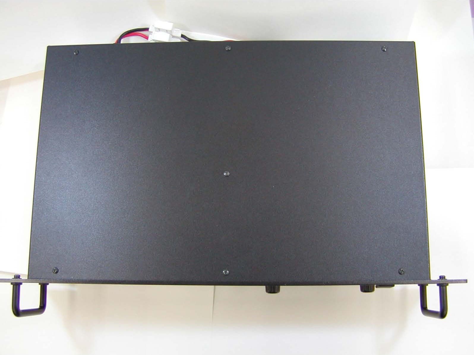
Click to zoom
Application Details
- Equipment Class
- TNB - Licensed Non-Broadcast Station Transmitter
- Date of Grant
- Feb 24, 2008
- Application Purpose
- Original Equipment
- Date of Application
- Feb 23, 2008
- Equipment Note
- IC-FR6000, UHF FM Repeater
- Frequency Range
- 406.10000000 - 470.00000000
- Company
- ICOM Incorporated
- Country
- Japan
Documents & Files
Document Text
Text extracted from the exhibit documents filed with the FCC. Open a document above to read the original.
Users Manual
INSTRUCTION MANUAL UHF FM REPEATER iFR6000 IMPORTANT R E A D T H I S I N S T RU C T I O N M A N UA L CAREFULLY before attempting to operate the re- peater. SAVE THIS INSTRUCTION MANUAL– This manual contains important safety and operating in- structions for the IC-FR6000 uhf fm repeater. EXPLICIT DEFINITIONS R WARNING HIGH VOLTAGE! NEVER at- tach an antenna or internal antenna connector during transmission. This may result in an electrical shock or burn. R WARNING HIGH VOLTAGE! NEVER in- stall the antenna at any place that person touch the antenna easily during transmission. This may result in an electrical shock or burn. R WARNING! NEVER apply AC to the DC power receptacle on the repeater rear panel. This could cause a fire or damage the repeater. R WARNING! NEVER apply more than 16 V DC, such as a 24 V battery, to the DC power receptacle on the repeater rear panel. This could cause a fire or damage the repeater. R CAUTION! NEVER let metal, wire or other ob- jects touch any internal part or connectors on the rear panel of the repeater. This may result in an electric shock. R CAUTION! NEVER expose the repeater to rain, snow or any liquids. DO NOT use or place the repeater in areas with t e m p e r a t u r e s b e l o w – 3 0 ° C ( – 2 2 ° F ) o r a b o ve +60°C (+140°F). Be aware that temperatures can ex- ceed 80°C (+176°F), resulting in permanent damage to the repeater if left there for extended periods. DO NOT place the repeater in excessively dusty envi- ronments or in direct sunlight. DO NOT put anything on top of the repeater. This will obstruct heat dissipation. Place the repeater in a secure place to avoid inadver- tent use by children. BE CAREFUL! The heatsink will become hot when operating the repeater continuously for long periods. BE CAREFUL! If a linear amplifier is connected, set the repeater’s RF output power to less than the linear amplifier’s maximum input level, otherwise, the linear amplifier will be damaged. Use Icom microphones only (optional). Other manu- facturer’s microphones have different pin assign- ments, and connection to the repeater may damage the repeater. Icom optional equipment is designed for optimal per- formance when used with this repeater. We are not responsible for the repeater being damaged or any accident caused when using non-Icom optional equip- ment. For U.S.A. only CAUTION: Changes or modifications to this repeater, not expressly approved by Icom Inc., could void your authority to operate this repeater under FCC regula- tions. PRECAUTIONS WORD R WARNING CAUTION NOTE DEFINITION Personal injury, fire hazard or electric shock may occur. Equipment damage may occur. If disregarded, inconvenience only. No risk of personal injury, fire or electric shock. Icom, Icom Inc. and the logo are registered trademarks of Icom Incorporated (Japan) in the United States, the United Kingdom, Germany, France, Spain, Russia and/or other countries. i ii SAFETY TRAINING INFORMATION W AR NING Your Icom radio generates RF electro- m agn e t ic e n e rgy d u ri n g t ra n s mi t mode. This radio is designed for and classified as “Occupational Use Only,” meaning it must be used only during the course of employment by individu- als aware of the hazards, and the ways to minimize such hazards. This radio is NOT intended for use by the “General Population” in an uncon- trolled environment. C AU TION To ensure that your exposure to RF electromagnetic energy is within the FCC allowable limits for occupational use, always adhere to the following guidelines: • DO NOT operate the radio without a proper antenna attached, as this may damage the radio and may also cause you to exceed FCC RF exposure limits. A proper antenna is the antenna supplied with this radio by the manufacturer or an antenna specifically authorized by the manufacturer for use with this ra- dio. • DO NOT transmit for more than 50% of total radio use time (“50% duty cycle”). Transmitting more than 50% of the time can cause FCC RF exposure com- pliance requirements to be exceeded. The radio is transmitting when the “TX indicator” lights red. You can cause the radio to transmit by pressing the “PTT” switch. Electromagnetic Interference/Compatibility During transmissions, your Icom radio generates RF energy that can possibly cause interference with other devices or systems. To avoid such interference, turn off the radio in areas where signs are posted to do so. DO NOT operate the transmitter in areas that are sensitive to electromagnetic radiation such as hospi- tals, aircraft, and blasting sites. FOR CLASS B UNINTENTIONAL RADIATORS This equipment has been tested and found to comply with the limits for a Class B digital devices, pursuant to Part 15 of the FCC Rules. These limits are designed to provide reasonable protection against harmful interference in a residential installation. This equipment generates, uses, and can radiate radio frequency energy and, if not installed and used in accordance with the instruction manual, may cause harmful interference to radio communications. However, there is no guarantee that interference will not occur in a particular installation. If this equipment does cause harmful interference to radio or television reception, which can be determined by turn- ing the equipment off and on, the user is encouraged to try to correct the interference by one of more of the following measures: • Reorient or relocate the receiving antenna • Increase the separation between the equipment and receiver • Connect the equipment into an outlet on a circuit differ - ent from that to which the receiver is connected. • Consult the dealer or an experienced radio/TV techni - cian for help. iii FORWARD Thank you for purchasing this Icom repeater. The IC-FR6000 uhf fm repeater is designed and built with Icom’s state of the art technology and craftsman- ship. With proper care, this product should provide you with years of trouble-free operation. We want to take a couple of moments of your time to thank you for ma…
Text truncated - open the document above for the full version.
Cover Letter(s)
February 19, 2008 AmericanTCB, Inc. 6731 Whittier Avenue, Suite C110 McLean, VA 22101 Subject: Equipment Authorization under FCC 47 CFR, Parts 2 and 90 (Subpart I) - Non-Broadcast Radio Transceivers Operating in the Frequency Band 406.1-470 MHz (25 kHz, 12.5 kHz and 6.25 kHz Channel Spacings). Applicant: ICOM Incorporated Product: UHF FM Repeater Model: IC-FR6000 FCC ID: AFJ306301 Dear Sir/Madam, As appointed agent for ICOM Incorporated, we submit the application to AmericanTCB, Inc. for certification of the above product. Please review all files uploaded to ATCB electronic filing site. If you have any queries, please do not hesitate to contact us by our TOLL FREE number: OUR TELEPHONE NO.: 1-877-747-6381 Yours truly, Tri Minh Luu, P. Eng., V.P., Engineering UltraTech Group of Labs Ultratech’s Accreditations: 0685 31040/SIT C-1376 46390-2049 200093-0 SL2-IN-E-1119R 3000 Bristol Circle, Oakville, Ontario, Canada L6H 6G4 Tel.: (905) 829-1570 Fax.: (905) 829-8050 Website: www.ultratech-labs.com Email: [email protected]
Cover Letter(s)
American Telecommunications Certification Body Inc. 6731 Whittier Ave, McLean, VA 22101 February 6, 2008 RE: FCC ID: AFJ306301_ATCB005907 Attention: Tri Luu I have a few comments on this Application. Please note that further comments may arise in response to answers provided to the questions below. 1. Please note that the FCC band listing policy does not allow the 406 – 606.1 MHz frequency band to be listed on a part 90 device. Please also note that there are no contiguous Part 90 frequencies between 222MHz to 406.1MHz. Consequently it is not be possible to list the 400 to 406.1MHz band on the FCC grant. The listing would be 406.1MHz to 470MHz. Please note that even if you could list from 400 to 406MHz, you would have to show how the device does not violate compliance to the particular rule parts involved (i.e. the technical sections of parts 25 etc) which has not been done. See Band listing KDB 634817 for reference. 2. Please note that test frequencies must be those in the rule section being certified (i.e. from the Aug 2009 FCC band listing policy KDB 634817 section f. “Test guidance” par (i). Test only on allowed frequencies). Please provide adequate justification showing the frequencies in the report were chosen as appropriate for testing to the requirement that only authorized/allowed frequencies be used as test frequencies in the FCC band listing policy (i.e. please show the particular Part 90 section involved). Please see the FCC band listing policy KDB 634817 for reference. Please provide data in line with the KDB band listing policy. 3. Please note that based on the responses to the above items, further comments may result. Dennis Ward mailto:[email protected] The items indicated above must be submitted before processing can continue on the above referenced application. Failure to provide the requested information may result in application termination. Correspondence should be considered part of the permanent submission and may be viewed from the Internet after a Grant of Equipment Authorization is issued. Please do not respond to this correspondence using the email reply button. In order for your response to be processed expeditiously, you must submit your documents through the AmericanTCB.com website. Also, please note that partial responses increase processing time and should not be submitted. Any questions about the content of this correspondence should be directed to the sender.
ID Label/Location Info
IC-FR6000 FCC ID LABEL CAUTION LABEL
Test Report
UHF FM Repeater Model No.: IC-FR6000 FCC ID: AFJ306301 Applicant: ICOM Incorporated 1-1-32, Kamiminami, Hirano-ku, Osaka 547-0003 Japan Tested in Accordance With Federal Communications Commission (FCC) 47 CFR, Parts 2 and 90 (Subpart I) UltraTech's File No.: ICOM-165F90 This Test report is Issued under the Authority of Tri M. Luu, Professional Engineer, Vice President of Engineering UltraTech Group of Labs Date: February 19, 2008 Report Prepared by: Dan Huynh Issued Date: February 19, 2008 Tested by: Wayne Wu and Hung Trinh Test Dates: December 11-18, 2007 January 2 &15, 2008 February 1-12, 2008 The results in this Test Report apply only to the sample(s) tested, and the sample tested is randomly selected. This report must not be used by the client to claim product endorsement by NVLAP or any agency of the US Government. UltraTech 3000 Bristol Circle, Oakville, Ontario, Canada, L6H 6G4 Tel.: (905) 829-1570 Fax.: (905) 829-8050 Website: www.ultratech-labs.com , Email: [email protected], Email: [email protected] 0685 31040/SIT C-1376 46390-2049 200093-0 SL2-IN-E-1119R FCC PARTS 2 & 90, SUBPART I, NON-BROADCAST RADIO TRANSCEIVERS Contents i UHF FM Repeater, Model IC-FR6000 FCC ID: AFJ306301 ULTRATECH GROUP OF LABS File #: ICOM-165F90 3000 Bristol Circle, Oakville, Ontario, Canada L6H 6G4 February 19, 2008 Tel. #: 905-829-1570, Fax. #: 905-829-8050, Email: [email protected] , Website: http://www.ultratech-labs.com All test results contained in this engineering test report are traceable to National Institute of Standards and Technology (NIST) TABLE OF CONTENTS EXHIBIT 1. SUBMITTAL CHECK LIST ..........................................................................................................................................1 EXHIBIT 2. INTRODUCTION ............................................................................................................................................................2 2.1. SCOPE ............................................................................................................................................................................................2 2.2. RELATED SUBMITTAL(S)/GRANT(S).......................................................................................................................................2 2.3. NORMATIVE REFERENCES .......................................................................................................................................................2 EXHIBIT 3. PERFORMANCE ASSESSMENT .................................................................................................................................3 3.1. CLIENT INFORMATION ..............................................................................................................................................................3 3.2. EQUIPMENT UNDER TEST (EUT) INFORMATION.................................................................................................................3 3.3. EUT’S TECHNICAL SPECIFICATIONS......................................................................................................................................4 3.4. LIST OF EUT’S PORTS.................................................................................................................................................................4 EXHIBIT 4. EUT OPERATING CONDITIONS AND CONFIGURATIONS DURING TESTS...................................................5 4.1. CLIMATE TEST CONDITIONS ...................................................................................................................................................5 4.2. OPERATIONAL TEST CONDITIONS & ARRANGEMENT FOR TEST SIGNALS.................................................................5 EXHIBIT 5. SUMMARY OF TEST RESULTS..................................................................................................................................6 5.1. LOCATION OF TESTS..................................................................................................................................................................6 5.2. APPLICABILITY & SUMMARY OF EMISSION TEST RESULTS............................................................................................6 5.3. MODIFICATIONS INCORPORATED IN THE EUT FOR COMPLIANCE PURPOSES............................................................6 5.4. DEVIATION OF STANDARD TEST PROCEDURES .................................................................................................................6 EXHIBIT 6. MEASUREMENTS, EXAMINATIONS & TEST DATA FOR EMC EMISSIONS ..................................................7 6.1. TEST PROCEDURES ....................................................................................................................................................................7 6.2. MEASUREMENT UNCERTAINTIES ..........................................................................................................................................7 6.3. MEASUREMENT EQUIPMENT USED .......................................................................................................................................7 6.4. ESSENTIAL/PRIMARY FUNCTIONS AS DECLARED BY THE MANUFACTURER ............................................................7 6.5. RF POWER OUTPUT [§§ 2.1046 & 90.205] ...................................................................................... ...........................................8 6.6. FREQUENCY STABILITY [§§ 2.1055 & 90.213] ........................................................................................................................9 6.7. AUDIO FREQUENCY RESPONSE [§ 2.1047(a)]....................................................................................................................... 11 6.8. MODULATION LIMITING [§§ 2.1047(b) & 90.210] ......................................................................................…
Text truncated - open the document above for the full version.
Contact Information
Applicant
Tatsuo Yano(General Manager of QA Department)
Technical Specifications
| # | Rule Parts | Frequency Range | Power Output | Emission | Tolerance |
|---|---|---|---|---|---|
| 2 | 9 | 406.1 MHz - 470 MHz | 5 W | 4K00F3E | 0.5 ppm |
Other Applications from ICOM Incorporated

AFJ460100
Aug 31, 2026VHF DSC Marine Radio
Equipment Class
TNB - Licensed Non-Broadcast Station Transmitter
AFJ453700
Jul 23, 2026Mobile Transceiver
Equipment Class
DTS - Digital Transmission System
AFJ452000
Jun 02, 2026VHF DIGITAL TRANSCEIVER
Equipment Class
TNF - Licensed Non-Broadcast Transmitter Held to Face
AFJ452100
May 12, 2026UHF DIGITAL TRANSCEIVER
Equipment Class
TNF - Licensed Non-Broadcast Transmitter Held to Face
AFJ444500
Sep 12, 2024Scanning Receiver
Equipment Class
CSR - Scanning Receiver