AFJ307400VHF Air Band Transceiver
ICOM Incorporated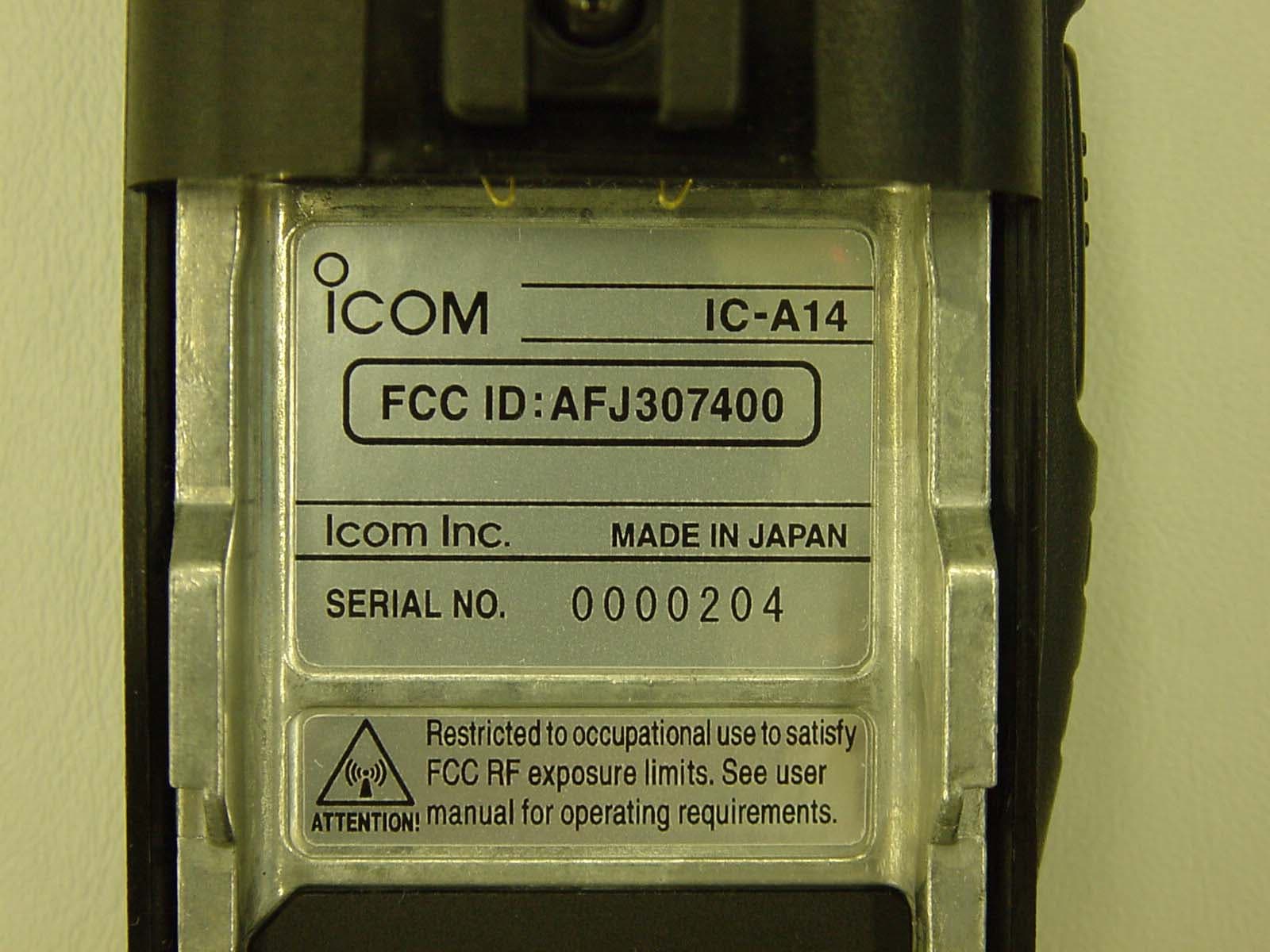
Click to zoom
Application Details
- Equipment Class
- TNF - Licensed Non-Broadcast Transmitter Held to Face
- Date of Grant
- Feb 06, 2008
- Application Purpose
- Original Equipment
- Date of Application
- Feb 04, 2008
- Equipment Note
- VHF Air Band Transceiver
- Frequency Range
- 118.00000000 - 136.97500000
- Company
- ICOM Incorporated
- Country
- Japan
Documents & Files
Document Text
Text extracted from the exhibit documents filed with the FCC. Open a document above to read the original.
Users Manual
INSTRUCTION MANUAL iA14 iA14S VHF AIR BAND TRANSCEIVER This device complies with Part 15 of the FCC Rules. Operation is subject to the condition that this device does not cause harmful inter- ference. YIC-A14YIC-A14S i SAFETY TRAINING INFORMATION W AR NING Your Icom radio generates RF electromagnetic energy dur- ing transmit mode. This radio is designed for and classified as “Occupational Use Only”, meaning it must be used only during the course of employment by individuals aware of the hazards, and the ways to minimize such hazards. This radio is NOT intended for use by the “General Population” in an uncontrolled environment. This radio has been evaluated for compliance at the distance of 2.5 cm with the FCC RF exposure limits for “Occupational Use Only”. In addition, your Icom radio complies with the following Standards and Guidelines with regard to RF energy and electromagnetic energy levels and evaluation of such levels for exposure to humans: • FCC OET Bulletin 65 Edition 97-01 Supplement C, Evaluating Com - pliance with FCC Guidelines for Human Exposure to Radio Frequency Electromagnetic Fields. • American National Standards Institute (C95.1-1992), IEEE Standard for Safety Levels with Respect to Human Exposure to Radio Frequency Electromagnetic Fields, 3 kHz to 300 GHz. • American National Standards Institute (C95.3-1992), IEEE Recom - mended Practice for the Measurement of Potentially Hazardous Electro- magnetic Fields– RF and Microwave. • The following accessories are authorized for use with this product. Use of accessories other than those specified may result in RF exposure lev- els exceeding the FCC requirements for wireless RF exposure.; Belt Clip (MB-94/96F) and Rechargeable Li-ion Battery Pack (BP-230N/ 232N). To ensure that your expose to RF electromagnetic en- ergy is within the FCC allowable limits for occupational use, always adhere to the following guidelines: • DO NOT operate the radio without a proper antenna attached, as this may damage the radio and may also cause you to exceed FCC RF ex- posure limits. A proper antenna is the antenna supplied with this radio by the manufacturer or antenna specifically authorized by the manufac- turer for use with this radio. • DO NOT transmit for more than 50% of total radio use time (“50% duty cycle”). Transmitting more than 50% of the time can cause FCC RF ex- posure compliance requirements to be exceeded. The radio is transmit- ting when “” appears on the function display. You can cause the radio to transmit by pressing the “PTT” switch. • ALWAYS keep the antenna at least 2.5 cm (1 inch) away from the body when transmitting and only use the Icom belt-clips which are listed on page 36 when attaching the radio to your belt, etc., to ensure FCC RF exposure compliance requirements are not exceeded. To provide the re- cipients of your transmission the best sound quality, hold the antenna at least 5 cm (2 inches) from your mouth, and slightly off to one side. The information listed above provides the user with the information needed to make him or her aware of RF exposure, and what to do to assure that this radio operates with the FCC RF exposure limits of this radio. Electromagnetic Interference/Compatibility During transmissions, your Icom radio generates RF energy that can possibly cause interference with other devices or systems. To avoid such interference, turn off the radio in areas where signs are posted to do so. DO NOT operate the transmitter in areas that are sensitive to electromagnetic radiation such as hospitals and blasting sites. Occupational/Controlled Use The radio transmitter is used in situations in which persons are exposed as consequence of their employment provided those persons are fully aware of the potential for exposure and can exercise control over their exposure. C AU TION ii FOREWORD Thank you for purchasing this Icom product. The IC-A14/S VHF AIR BAND TRANSCEIVER is designed and built with Icom’s state of the art technology and craftsmanship. With proper care this product should provide you with years of trouble-free operation. IMPORTANT READ ALL INSTRUCTIONS carefully and completely before using the transceiver. SAVE THIS INSTRUCTION MANUAL— This in- struction manual contains important operating instructions for the IC-A14/S. EXPLICIT DEFINITIONS SUPPLIED ACCESSORIES The following accessories are supplied with the transceiver. Qty. q Flexible antenna ............................................................. 1 w Battery pack ................................................................... 1 e Belt clip .......................................................................... 1 r Hand strap ..................................................................... 1 t Battery charger .............................................................. 1 y AC adapter ..................................................................... 1 WORD DEFINITION RWARNING CAUTION NOTE Personal injury, fire hazard or electric shock may occur. If disregarded, inconvenience only. No risk of personal injury, fire or electric shock. Equipment damage may occur. qw ty e r R WARNING! NEVER hold the transceiver so that the antenna is very close to, or touching exposed parts of the body, especially the face or eyes, while transmitting. The transceiver will perform best if the microphone is 5 to 10 cm (2 31 ⁄32 to 3 15 ⁄16 inch) away from the lips and the transceiver is vertical. R WARNING! NEVER operate the transceiver with a headset or other audio accessories at high volume levels. Hearing experts advise against continuous high volume op- eration. If you experience a ringing in your ears, reduce the volume level or discontinue use. NEVER short the terminals of the battery pack. Also, cur- rent may flow into nearby metal objects, such as a necklace, etc. Therefore, be careful when carrying with, or placing near metal objects, carrying in handbags, etc. NEVER use of non-Icom battery packs/chargers to prevent the loss of the trans…
Text truncated - open the document above for the full version.
Cover Letter(s)
January 4, 2008 AmericanTCB, Inc. 6731 Whittier Avenue, Suite C110 McLean, VA 22101 Subject: New Certification Application under FCC 47 CFR, Parts 2 and 87 (Subpart D) - Non-broadcast Aviation Radio Services Operating in the Frequency Band 118-136.975 MHz. Applicant: ICOM Incorporated Product: VHF Air Band Transceiver Model: IC-A14, IC-A14S FCC ID: AFJ307400 Dear Sir/Madam, As appointed agent for ICOM Incorporated, we would like to submit the application to AmericanTCB, Inc. for certification of the above product. Please review all files uploaded to AmericanTCB electronic filing site. If you have any queries, please do not hesitate to contact us. Yours truly, Tri Minh Luu, P. Eng., V.P., Engineering Encl. UltraTech Group of Labs Ultratech’s Accreditations: 0685 31040/SIT C-1376 46390-2049 200093-0 SL2-IN-E-1119R 3000 Bristol Circle, Oakville, Ontario, Canada L6H 6G4 Tel.: (905) 829-1570 Fax.: (905) 829-8050 Website: www.ultratech-labs.com Email: [email protected]
Cover Letter(s)
American Telecommunications Certification Body Inc. 6731 Whittier Ave, McLean, VA 22101 February 5, 2008 RE: FCC ID: AFJ307400_ATCB005894 Attention: Tri Luu I have a few comments on this Application. Please note that further comments may arise in response to answers provided to the questions below. 1. Please note that TIA603 and the FCC rules require that ERP/EIRP values are to be actual measured values using antenna substitution methods and are not to be calculated. Please note that section 5.10 of the report states “(1) If the transmitter’s antenna is an integral part of the EUT, the ERP is measured using substitution method. (2) If the transmitter’s antenna is non- integral and diverse, the lowest ERP of the carrier with 0 dBi antenna gain is used for calculation of the spurious/harmonic emissions in dBc.” Then the tables in section 5.10.3 state ERP measured by substation. The antenna is listed as a non-integral antenna. This is confusing as the methods stated do not appear to agree. In any event, antenna substitution method is to be used regardless of antenna type for spurious emissions. It would help if you verified the data by providing the signal generator values and antenna substitution gain values to confirm measured ERP was performed. Please confirm that measured ERP was performed in accordance to TIA603 and section 8.2.2 of the report and that item 2 of section 5.10 was not used. 2. Please note that in the 99% BW plots the reference level used is 10W (40dBm) and it looks like the 99% is taken from that level. However, that appears to be the limit from the standard and not the actual CW output of your device. The 99% BW should be taken using the CW reference from the actual output of the EUT or from the peak of the modulated signal in some instances. Please Explain. 3. The FCC requires a letter from the FAA for the frequency band used by this device. Please provide the letter per 87.147(d)(2). Dennis Ward mailto:[email protected] The items indicated above must be submitted before processing can continue on the above referenced application. Failure to provide the requested information may result in application termination. Correspondence should be considered part of the permanent submission and may be viewed from the Internet after a Grant of Equipment Authorization is issued. Please do not respond to this correspondence using the email reply button. In order for your response to be processed expeditiously, you must submit your documents through the AmericanTCB.com website. Also, please note that partial responses increase processing time and should not be submitted. Any questions about the content of this correspondence should be directed to the sender.
Cover Letter(s)
1 dward From: [email protected] Sent: 02/06/2008 1:21 PM To: [email protected] Cc: [email protected]; [email protected]; [email protected]; [email protected] Subject: MESSAGE/uelrfiatcb/AFJ307400_ATCB005894 From: Mr. Tri Luu (uelrfiatcb) mailto:[email protected] Q1. Please note that TIA603 and the FCC rules require that ERP/EIRP values are to be actual measured values using antenna substitution methods and are not to be calculated. Please note that section 5.10 of the report states “(1) If the transmitter’s antenna is an integral part of the EUT, the ERP is measured using substitution method. (2) If the transmitter’s antenna is nonintegral and diverse, the lowest ERP of the carrier with 0 dBi antenna gain is used for calculation of the spurious/harmonic emissions in dBc.” Then the tables in section 5.10.3 state ERP measured by substation. The antenna is listed as a non- integral antenna. This is confusing as the methods stated do not appear to agree. In any event, antenna substitution method is to be used regardless of antenna type for spurious emissions. It would help if you verified the data by providing the signal generator values and antenna substitution gain values to confirm measured ERP was performed. Please confirm that measured ERP was performed in accordance to TIA603 and section 8.2.2 of the report and that item 2 of section 5.10 was not used. A1. ERP for harmonics were performed using substitution method. the description of 5.10 was partially intended for ERP carrier to calculate dBc values for both ERP harmonics and Limit due to our existing report format. We will revise the format in the furture project so that ERP harmonic in dBm can be directly compared to FCC's dBm limit. Q2. Please note that in the 99% BW plots the reference level used is 10W (40dBm) and it looks like the 99% is taken from that level. However, that appears to be the limit from the standard and not the actual CW output of your device. The 99% BW should be taken using the CW reference from the actual output of the EUT or from the peak of the modulated signal in some instances. Please Explain. A2. 99% OBW has been performed using the built in automatic function of spectrum analyzer and 40 dBm of reference level was simply selected as a value which will not saturate the output reading at the peak. In other words, 99% OBW was not taken from 40dBm reference level but was calculated automatically by analyzer. The revised test report has been uploaed to ATCB to explcitly indicate this. We don't see any reason that the peak of actual measurement should be used as reference level in 99% OBW measurement so please kindly advise us where we can find the reference or rule part for this requirement. Q3. The FCC requires a letter from the FAA for the frequency band used by this device. Please provide the letter per 87.147(d)(2). A3. FAA letter has been uploaded to ATCB.
RF Exposure Info
VHF Air Band Transceiver - IC-A14, IC-A14S (FCC ID: AFJ307400) FCC power thresholds: f GHz 900/f Face-held controlled d >= 2.5 cm 0.1285 7,000 mW 0.15 6,000 mW 1. 900/f = face-held controlled 2. d is the distance to a person’s body. No evaluation required if power is below this threshold: f GHz P out 0.1285 7,000 mW RF conducted mean power measured = 1,469 mW Crest Factor (PEP/CW) = 5.0 W /1.5 W = 3.333 User-based time-average factor = 50 % = 0.5 Antenna Gain = -1.5 dB Threshold for no SAR evaluation is 7,000 mW Transmitter peak power is 1,469 mW X 3.333 X 0.5 = 2,448 mW. Conclusion: No SAR evaluation required since Transmitter Power is below FCC power thresholds Distance from the antenna with the thinnest belt-clip (M/N: MB-94) mounted Antenna Information M/N: FA-B02AR Manufacturer: ICOM Gain: -1.5 dB Type: ¼ wave whip antenna Remark: The above information had been provided by the manufacturer
Test Report
VHF Air Band Transceiver Model No.: IC-A14, IC-A14S FCC ID: AFJ307400 Applicant: ICOM Incorporated 1-1-32, Kamiminami, Hirano-ku Osaka Japan, 547-0003 Tested in Accordance With Federal Communications Commission (FCC) 47 CFR, Parts 2 and 87 (Subpart D) – Aviation Services UltraTech's File No.: ICOM-164F87 This Test report is Issued under the Authority of Tri M. Luu, Professional Engineer, Vice President of Engineering UltraTech Group of Labs Date: January 4, 2008 Report Prepared by: JaeWook Choi Issued Date: January 4, 2008 Tested by: Wayne Wu, EMI/RFI Technician Hung Trinh, EMI/RFI Technician Test Dates: November 03, 23, 26 & 28/ 2007 The results in this Test Report apply only to the sample(s) tested, and the sample tested is randomly selected. This report must not be used by the client to claim product endorsement by NVLAP or any agency of the US Government. UltraTech 3000 Bristol Circle, Oakville, Ontario, Canada, L6H 6G4 Tel.: (905) 829-1570 Fax.: (905) 829-8050 Website: www.ultratech-labs.com , Email: [email protected], Email: [email protected] 0685 31040/SIT C-1376 46390-2049 200093-0 SL2-IN-E-1119R FCC Parts 2 and 87, Subpart D, Non-Broadcast Aviation Radio Services Page 1 VHF Air Band Transceiver, Model(s): IC-A14, IC-A14S FCC ID: AFJ307400 TABLE OF CONTENTS EXHIBIT 1. INTRODUCTION ......................................................................................................................................... 3 1.1. SCOPE......................................................................................................................................................................... 3 1.2. RELATED SUBMITTAL(S)/GRANT(S)................................................................................................................... 3 1.3. NORMATIVE REFERENCES ................................................................................................................................... 3 EXHIBIT 2. PERFORMANCE ASSESSMENT .............................................................................................................. 4 2.1. CLIENT INFORMATION .......................................................................................................................................... 4 2.2. EQUIPMENT UNDER TEST (EUT) INFORMATION ............................................................................................. 4 2.3. EUT’S TECHNICAL SPECIFICATIONS ..................................................................................................................5 2.4. LIST OF EUT’S PORTS ............................................................................................................................................. 5 EXHIBIT 3. EUT OPERATING CONDITION AND CONFIGURATIONS DURING TESTS ................................. 6 3.1. CLIMATE TEST CONDITIONS ................................................................................................................................ 6 3.2. OPERATIONAL TEST CONDITIONS & ARRANGEMENT FOR TEST SIGNALS .............................................. 6 EXHIBIT 4. SUMMARY OF TEST RESULTS ............................................................................................................... 7 4.1. LOCATION OF TESTS .............................................................................................................................................. 7 4.2. APPLICABILITY & SUMMARY OF EMISSION TEST RESULTS ........................................................................ 7 4.3. MODIFICATIONS INCORPORATED IN THE EUT FOR COMPLIANCE PURPOSES ........................................ 7 4.4. DEVIATION OF STANDARD TEST PROCEDURES.............................................................................................. 7 EXHIBIT 5. MEASUREMENTS, EXAMINATIONS & TEST DATA FOR EMC EMISSIONS............................... 8 5.1. TEST PROCEDURES................................................................................................................................................. 8 5.2. MEASUREMENT UNCERTAINTIES ...................................................................................................................... 8 5.3. MEASUREMENT EQUIPMENT USED.................................................................................................................... 8 5.4. ESSENTIAL/PRIMARY FUNCTIONS AS DECLARED BY THE MANUFACTURER ......................................... 8 5.5. RF POWER OUTPUT [§§ 2.1046 & 87.131] .............................................................................................................. 9 5.5.1. Limits ................................................................................................................................................................... 9 5.5.2. Method of Measurements..................................................................................................................................... 9 5.5.3. Test Arrangement ................................................................................................................................................ 9 5.5.4. Test Data ............................................................................................................................................................. 9 5.6. MODULATION CHARACTERISTICS - AUDIO FREQUENCY RESPONSE [§§ 2.1047(A) & 87.141(F)].......... 10 5.6.1. Limits ................................................................................................................................................................. 10 5.6.2. Method of Measurements................................................................................................................................... 10 5.6.3. Test Arrangement .............................................................................................................................................. 10 5.6.4. Test Data .........................................…
Text truncated - open the document above for the full version.
Contact Information
Applicant
Tatsuo Yano(General Manager of QA Department)
Technical Specifications
| # | Rule Parts | Frequency Range | Power Output | Emission | Tolerance |
|---|---|---|---|---|---|
| 1 | 87 | 118 MHz - 136.975 MHz | 1.469 W | 6K00A3E | 5.0000000000 ppm |
Other Applications from ICOM Incorporated

AFJ460100
Aug 31, 2026VHF DSC Marine Radio
Equipment Class
TNB - Licensed Non-Broadcast Station Transmitter
AFJ453700
Jul 23, 2026Mobile Transceiver
Equipment Class
DTS - Digital Transmission System
AFJ452000
Jun 02, 2026VHF DIGITAL TRANSCEIVER
Equipment Class
TNF - Licensed Non-Broadcast Transmitter Held to Face
AFJ452100
May 12, 2026UHF DIGITAL TRANSCEIVER
Equipment Class
TNF - Licensed Non-Broadcast Transmitter Held to Face
AFJ444500
Sep 12, 2024Scanning Receiver
Equipment Class
CSR - Scanning Receiver