AFJ322800Class B AIS Transponder
ICOM Incorporated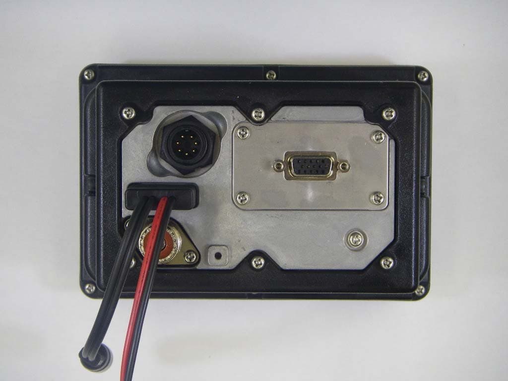
Click to zoom
Application Details
- Equipment Class
- AIS - Automatic Identification Systems
- Date of Grant
- Aug 03, 2011
- Application Purpose
- Original Equipment
- Date of Application
- Aug 03, 2011
- Equipment Note
- Class B AIS Transponder
- Frequency Range
- 156.02500000 - 162.02500000
- Company
- ICOM Incorporated
- Country
- Japan
Documents & Files
Document Text
Text extracted from the exhibit documents filed with the FCC. Open a document above to read the original.
Users Manual
INSTRUCTION MANUAL New2001 MA-500TR CLASS B AIS TRANSPONDER New2001 i FOREWORD Thank you for purchasing this Icom product. The MA-500TR c l a s s b a i s t r a n s p o n d e r is designed and built with Icom’s state of the art technology and craftsman- ship. With proper care, this product should provide you with years of trouble-free operation. We appreciate you making the MA-500TR your transpon- der of choice, and hope you agree with Icom’s philosophy of “technology first.” Many hours of research and development went into the design of your MA-500TR. D FEATURES ❍ Full dot-matrix display visually shows real-time vessel traffic information ❍ IPX7 waterproof protection ❍ 3 lines of NMEA0183 Input/Output ❍ GPS receiver comes with the MA-500TR ❍ Collision-risk management functions ❍ Integration with Icom VHF transceivers * * See the leaflet that comes with the transponder for details of the corresponding transceiver. IMPORTANT READ ALL INSTRUCTIONS carefully and completely before using the transponder. SAVE THIS INSTRUCTION MANUAL — This in- struction manual contains important operating instructions for the MA-500TR. EXPLICIT DEFINITIONS WORDDEFINITION RWARNING! Personal injury, fire hazard or electric shock may occur. CAUTION Equipment damage may occur. NOTE If disregarded, inconvenience only. No risk of personal injury, fire or electric shock. CLEAN THE TRANSPONDER THOROUGHLY WITH FRESH WATER after exposure to saltwater, otherwise, the keys and switch may become inoperable due to salt crystal- lization. ii New2001 FCC INFORMATION • FOR CLASS B UNINTENTIONAL RADIATORS This equipment has been tested and found to comply with the limits for a Class B digital device, pursuant to part 15 of the FCC Rules. These limits are designed to provide reasonable protection against harmful interference in a residential instal- lation. This equipment generates, uses and can radiate radio frequency energy and, if not installed and used in accordance with the instructions, may cause harmful interference to radio communications. However, there is no guarantee that inter- ference will not occur in a particular installation. If this equip- ment does cause harmful interference to radio or television reception, which can be determined by turning the equipment off and on, the user is encouraged to try to correct the inter- ference by one or more of the following measures: • Reorient or relocate the receiving antenna. • Increase the separation between the equipment and receiver. • Connect the equipment into an outlet on a circuit different from that to which the receiver is connected. • Consult the dealer or an experienced radio/TV technician for help. SUPPLIED ACCESSORIES Mounting bracket For the mounting bracket DC power cable (OPC-2059) Knob bolts Screws (5×20) Flat washers (M5) Spring washers (M5) NMEA connector cable (OPC-2014) MXG-5000 g p s r e c e i v e r is included with MA-500TR. MXG-5000 (Referred to as Internal GPS) Cable length: Approx. 10 m (32.8 ft) • An instruction sheet comes with the MXG- 5000. Please read it before installing and operating the MXG-5000. • The OPC-2014 has 15 leads, numbered 1 to 15. iii New2001 RADIO OPERATOR WARNING WARNING Icom requires the radio operator to meet the FCC Requirements for Radio Frequency Expo- sure. An omnidirectional antenna with gain not greater than 9 dBi must be mounted a minimum of 5 meters (measured from the lowest point of the antenna) vertically above the main deck and all possible personnel. This is the minimum safe separation distance estimated to meet all RF exposure compliance re- quirements. This 5 meter distance is based on the FCC Safe Maximum Permissible Exposure (MPE) distance of 3 meters added to the height of an adult (2 meters) and is appropriate for all vessels. For watercraft without suitable structures, the antenna must be mounted so as to maintain a minimum of 1 meter vertically between the antenna, (measured from the lowest point of the antenna), to the heads of all persons AND all persons must stay outside of the 3 meter MPE radius. Do not transmit with radio and antenna when persons are within the MPE radius of the antenna, unless such persons (such as driver or radio operator) are shielded from antenna field by a grounded metallic barrier. The MPE Radius is the minimum distance from the antenna axis that person should maintain in order to avoid RF exposure higher than the allow- able MPE level set by FCC. FAILURE TO OBSERVE THESE LIMITS MAY ALLOW THOSE WITHIN THE MPE RADIUS TO EXPERIENCE RF RADIATION ABSORPTION WHICH EXCEEDS THE FCC MAXIMUM PERMISSIBLE EXPOSURE (MPE) LIMIT. IT IS THE RESPONSIBILITY OF THE RADIO OPERATOR TO ENSURE THAT THE MAXIMUM PERMISSIBLE EXPO- SURE LIMITS ARE OBSERVED AT ALL TIMES DURING RADIO TRANSMISSION. THE RADIO OPERATOR IS TO ENSURE THAT NO BYSTANDERS COME WITHIN THE RADIUS OF THE MAXIMUM PERMISSIBLE EXPOSURE LIMITS. Determining MPE Radius THE MAXIMUM PERMISSIBLE EXPOSURE (MPE) RADIUS HAS BEEN ESTIMATED TO BE A RADIUS OF ABOUT 3M PER OET BULLETIN 65 OF THE FCC. THIS ESTIMATE IS MADE ASSUMING THE MAXIMUM POWER OF THE RADIO AND ANTENNAS WITH A MAXI- MUM GAIN OF 9dBi ARE USED FOR A VESSEL MOUNTED SYSTEM. iv New2001 1 2 3 4 5 6 7 8 9 10 11 12 13 14 15 16 • INSTALLATION NOTES The installation of this equipment should be made in such a manner as to respect the EC recommended electromagnetic field exposure limits (1999/519/EC). The maximum RF power available from this device is 2 watts. The antenna should be installed as high as possible for maxi- mum efficiency and that this installation height should be at least 5 meters above ground (or accessible) level. In the case where an antenna cannot be installed at a reasonable height, then the transmitter should neither be continuously operated for long periods if any person is within 5 meters of the antenna, nor operated at all if any person is touching the antenna. In all cases any possible risk depends on the transmitter being activated for long periods. (actual recom…
Text truncated - open the document above for the full version.
Cover Letter(s)
August 02, 2011 Ultratech Engineering Labs, Inc. 3000 Bristol Circle Oakville, Ontario L6H 6G4 Subject: Equipment Authorization under FCC 47 CFR, Parts 2, 80 (Marine in 156.025–162.025 MHz Band) - Non-Broadcast Radio Transceivers. Applicant: ICOM Incorporated Product: Class B AIS Transponder Model: MA-500TR FCC ID: AFJ322800 Dear Sir/Madam, As appointed agent for ICOM Incorporated, We would like to submit FCC certification application of the above product. Please find USCG approval letter, submitted reports and application documents as specified in Section 80.231 of the FCC rule uploaded to your E-filing site. If you have any queries, please do not hesitate to contact us. Yours truly, Dharmajit Solanki Dharmajit Solanki Authorized Agent UltraTech Group of Labs FCC TCB & IC CB Ultratech’s Accreditations: 0685 FCC 91038 1309 46390-2049 NVLAP Lab Code 200093-0 SL2-IN-E-1119R Korea KCC-RRL CA2049 3000 Bristol Circle, Oakville, Ontario, Canada L6H 6G4 Tel.: (905) 829-1570 Fax.: (905) 829-8050 Website: www.ultratech-labs.com Email: [email protected]
Cover Letter(s)
S t a t e m e n t of Opinion No.: 10214216/AA/00 With respect to Chapter 10 of the Telecommunications Act of The Netherlands, Telefication declares that to our opinion the listed product complies with the essential requirements, in accordance with Article 3 of the Directive 1999/5/EC, as indicated under Annex 1 of this statement. Product description: Class-B AIS Transponder Trademark: ICOM Family name: -- Type designation: MA-500TR / MXG-5000 Serial No: -- Hard- / Softw. release No: -- Manufacturer: Icom Incorporated Address: 1-1-32 Kamiminami,Hirano-Ku City: 547-0003 Osaka Country: Japan This statement is granted to: Name: Icom Incorporated Address: 1-1-32 Kamiminami,Hirano-Ku City: 547-0003 Osaka Country: Japan This statement has THREE Annexes. Zevenaar, 14 January 2011 W.J.M. Jong Operations Manager Certification For each product to which this Statement of Opinion relates (see annex 3) our opinion with respect to the essential requirements is as follows: Article 3.1 *) In addition standards published under Directives 2006/95/EC, 2004/108/EC, 90/385/EEC and 93/42/EEC may have been used to demonstrate compliance with articles 3.1.a and 3.1.b of Directive 1999/5/EC. Article 3.2 Article 3.3 Opinions Annex 1 to Statement of Opinion14 January 2011 Number: 10214216/AA/00Annex 1, Page 1 of 2 C(a) The protection of the health and safety of the user and other person, including the objectives with respect to safety requirements contained in Directive 73/23/EEC *) , but with no voltage limit applying. C(b) The protection requirements with respect to electromagnetic compatibility contained in Directive 89/336/EEC *) . CThe radio product shall be so constructed that it effectively uses the spectrum allocated to terrestrial/space radio communication and orbital resources so as to avoid harmful interference. NA (a) The product shall be so constructed that it interworks via networks with other apparatus and that it can be connected to interfaces of the appropriate type throughout the Community. NA (b) The product shall be so constructed that it does not harm the network or its functioning nor misuse network resources, thereby causing an unacceptable degradation of service. NA (c) The product shall be so constructed that it incorporates safeguards to ensure that the personal data and privacy of the user and of the subscriber are protected. NA (d) The product shall be so constructed that it supports certain features ensuring avoidance of fraud. C(e) The product shall be so constructed that it supports certain features ensuring access to emergency services. NA(f) The product shall be so constructed that it supports certain features in order to facilitate its use by users with a disability. C=Conform NC=Not Conform NA=Not applicable (for this product) NP=Not performed (in this statement) Telefication, Edisonstraat 12A, 6902 PK Zevenaar, The Netherlands Tel: +31 316 583 180, Fax: +31 316 583 189 Remarks and observations The following conditions are applicable: Annex 1 to Statement of Opinion14 January 2011 Number: 10214216/AA/00Annex 1, Page 2 of 2 •The validity of this Statement of Opinion is limited to products, which are equal to the one examined in the type-examination. •When the manufacturer (or holder of this statement) is placing the product on the European market or the countries of the EEA, the marking of this product must contain (among other elements) the Notified Body number of Telefication: 0560 •This Statement of Opinion does not imply that the product can be used in the European Union or the countries of the EEA. If the product can not be identified as 'class-1' in accordance with Commision Decision 2000/299/EC, then: - Placing the product on the market may be subject to notification to the national radio agencies. - Putting the product into service is subject to national frequency regulation and may require licencing. Model MA-500TR is Class B AIS Transponder. Model MXG-5000 is GPS Receiver. MA-500TR incorporates two separate non identical TDMA receivers; DSC-reception is time-shared with both TDMA receivers. Telefication, Edisonstraat 12A, 6902 PK Zevenaar, The Netherlands Tel: +31 316 583 180, Fax: +31 316 583 189 Annex 2 to Statement of Opinion14 January 2011 Number: 10214216/AA/00Annex 2, Page 1 of 2 Documentation lodged for this Statement of Opinion Test Reports: Product Documentation: Technical Standards and Specifications The following standards have been used in full or part to cover the essential requirements: -----BSH: BSH/46162/4321440/10-01, 13 December 2010 -----BSH: BSH/46162/4321440/10-02, 03 December 2010 -----Icom Incorporated: TCF/MA-500TR MXG-5000, 16 December 2010 -----Assembly drawings -----Bill of materials -----Block diagram -----Electric diagrams -----Photos -----User manual -----Waivers -----EN 60945October 2002Edition 4 -----EN 60950-12006 -----EN 60950-1/A11March 2009 -----IEC 61108-1July 20032nd Ed. -----IEC 62287-1March 2006First Ed. Telefication, Edisonstraat 12A, 6902 PK Zevenaar, The Netherlands Tel: +31 316 583 180, Fax: +31 316 583 189 Annex 2 to Statement of Opinion14 January 2011 Number: 10214216/AA/00Annex 2, Page 2 of 2 Technical features and characteristics The product includes the following features and characteristics: AIS equipment: -----Operating frequency range: 156.025 - 162.025 MHz -----Maximum output power: 2 W rated -----Modulation method(s): GMSK Telefication, Edisonstraat 12A, 6902 PK Zevenaar, The Netherlands Tel: +31 316 583 180, Fax: +31 316 583 189 Annex 3 to Statement of Opinion14 January 2011 Number: 10214216/AA/00Annex 3, Page 1 of 1 The product as described in this Statement of Opinion includes the following type designations: Product description:Class-B AIS Transponder Type designation:MA-500TR / MXG-5000 Trademark:ICOM Serial No:-- Hard- / Softw. release No:-- Telefication, Edisonstraat 12A, 6902 PK Zevenaar, The Netherlands Tel: +31 316 583 180, Fax: +31 316 583 189
ID Label/Location Info
SERIAL NO. STICKER
ID Label/Location Info
INSTRUCTION MANUAL New2001 MA-500TR CLASS B AIS TRANSPONDER This device complies with Part 15 of the FCC Rules. Operation is subject to the condition that this device does not cause harmful interference.
RF Exposure Info
iii New2001 RADIO OPERATOR WARNING WARNING Icom requires the radio operator to meet the FCC Requirements for Radio Frequency Expo- sure. An omnidirectional antenna with gain not greater than 9 dBi must be mounted a minimum of 5 meters (measured from the lowest point of the antenna) vertically above the main deck and all possible personnel. This is the minimum safe separation distance estimated to meet all RF exposure compliance re- quirements. This 5 meter distance is based on the FCC Safe Maximum Permissible Exposure (MPE) distance of 3 meters added to the height of an adult (2 meters) and is appropriate for all vessels. For watercraft without suitable structures, the antenna must be mounted so as to maintain a minimum of 1 meter vertically between the antenna, (measured from the lowest point of the antenna), to the heads of all persons AND all persons must stay outside of the 3 meter MPE radius. Do not transmit with radio and antenna when persons are within the MPE radius of the antenna, unless such persons (such as driver or radio operator) are shielded from antenna field by a grounded metallic barrier. The MPE Radius is the minimum distance from the antenna axis that person should maintain in order to avoid RF exposure higher than the allow- able MPE level set by FCC. FAILURE TO OBSERVE THESE LIMITS MAY ALLOW THOSE WITHIN THE MPE RADIUS TO EXPERIENCE RF RADIATION ABSORPTION WHICH EXCEEDS THE FCC MAXIMUM PERMISSIBLE EXPOSURE (MPE) LIMIT. IT IS THE RESPONSIBILITY OF THE RADIO OPERATOR TO ENSURE THAT THE MAXIMUM PERMISSIBLE EXPO- SURE LIMITS ARE OBSERVED AT ALL TIMES DURING RADIO TRANSMISSION. THE RADIO OPERATOR IS TO ENSURE THAT NO BYSTANDERS COME WITHIN THE RADIUS OF THE MAXIMUM PERMISSIBLE EXPOSURE LIMITS. Determining MPE Radius THE MAXIMUM PERMISSIBLE EXPOSURE (MPE) RADIUS HAS BEEN ESTIMATED TO BE A RADIUS OF ABOUT 3M PER OET BULLETIN 65 OF THE FCC. THIS ESTIMATE IS MADE ASSUMING THE MAXIMUM POWER OF THE RADIO AND ANTENNAS WITH A MAXI- MUM GAIN OF 9dBi ARE USED FOR A VESSEL MOUNTED SYSTEM. Industry Canada RSS-182, Issue 4 Page 30 Class B AIS Transponder, Model MA-500TR IC: 202D-322800 B ULTRATECH GROUP OF LABS File #: ICOM-235_RSS182 3000 Bristol Circle, Oakville, Ontario, Canada L6H 6G4 February 9, 2011 Tel. #: 905-829-1570, Fax. #: 905-829-8050, Email: [email protected] , Website: http://www.ultratech-labs.com All test results contained in this engineering test report are traceable to National Institute of Standards and Technology (NIST) 5.7. RF EXPOSURE REQUIREMENTS [RSS-102] The criteria listed in the following table shall be used to evaluate the environmental impact of human exposure to radio-frequency (RF) radiation. Calculation Method of RF Safety Distance : S = PG/4r 2 =EIRP/4r 2 Where: P: power input to the antenna in mW EIRP: Equivalent (effective) isotropic radiated power. S: power density mW/cm 2 G: numeric gain of antenna relative to isotropic radiator r: distance to centre of radiation in cm r = PG/4S Industry Canada RSS-182, Issue 4 Page 31 Class B AIS Transponder, Model MA-500TR IC: 202D-322800 B ULTRATECH GROUP OF LABS File #: ICOM-235_RSS182 3000 Bristol Circle, Oakville, Ontario, Canada L6H 6G4 February 9, 2011 Tel. #: 905-829-1570, Fax. #: 905-829-8050, Email: [email protected] , Website: http://www.ultratech-labs.com All test results contained in this engineering test report are traceable to National Institute of Standards and Technology (NIST) 5.7.1. Test Data Antenna Gain Limit specified by Manufacturer: 9 dBi (1) Lowest Frequency (MHz) Measured Peak RF Conducted Power (dBm) Calculated EIRP (dBm) Exposure Condition Calculated Minimum RF Safety Distance r (cm)* 156.025 32.74 41.74 General Population 78 * The minimum separation distance between the antenna and bodies of users are calculated using the following formula: RF EXPOSURE DISTANCE LIMITS: r = (PG/4S) 1/2 = (EIRP/4S) 1/2 Power Density for General Population Use = S = 0.2 mW/cm 2 r = (EIRP/4ПS) 1/2 = (14928/(4П(0.2)) ½ = 77.09 cm Evaluation of RF Exposure Compliance Requirements RF Exposure Requirements Compliance with FCC Rules Minimum calculated separation distance between antenna and persons required: 78 cm Manufacturer’ instruction for separation distance between antenna and persons required: 300 cm Antenna installation and device operating instructions for installers (professional/unskilled users), and the parties responsible for ensuring compliance with the RF exposure requirement Please refer to User’s Manual for details. Caution statements and/or warning labels that are necessary in order to comply with the exposure limits Please refer to Page iii of User’s Manual for RF Exposure Information. Any other RF exposure related issues that may affect MPE compliance None
Test Report
Bundesamt für Seeschifffahrt und Hydrographie Federal Maritime and Hydrographic Agency Test Report No.. BSH/46162/4321440/10-1Date: 13.12.2010page 2 of 113 Bundesamt für Seeschifffahrt und Hydrographie Federal Maritime and Hydrographic Agency Test Report No.. BSH/46162/4321440/10-1Date: 13.12.2010page 3 of 113 General Applicant:Pete Hizzey 5 Boulevard Libre Echange, 2AC Champs Pinsons, 31650 Saint-Orens de Gameville, France Equipment under test: Type:MA-500TR Manufacturer: ICOM Incorporated 2-1-32 Kamiminami, Hirano-Ku, Osaka 547-0003, Japan Place of test:BSH test laboratory Hamburg, Room 916 Start of test:8 Feburary 2010 End of test:30 November 2010 Test standards 1 : IEC 62287-1 Maritime navigation and radiocommunication equipment and systems- Automatic Identification Systems Class B shipborne equipment of the Universal Automatic Identification System (AIS) using CSTMA techniques Summary Test No. ReferenceSectionResult (passed/ not passed / not applicable / not tested) 2 IEC 62287 10 Operational testsPassed 3 IEC 62287 11 Physical testsNot included 4 IEC 62287 12 Specific tests of link layerPassed 5 IEC 62287 13 Specific tests of network layerPassed 6 IEC 62287 C.3 DSC functionality testsPassed 1 Numbers listed in the titles of the test sections of this report refer to the respective sections of IEC 61993-2 if not stated otherwise. Bundesamt für Seeschifffahrt und Hydrographie Federal Maritime and Hydrographic Agency Test Report No.. BSH/46162/4321440/10-1Date: 13.12.2010page 4 of 113 GENERAL......................................................................................................................................................................3 SUMMARY ....................................................................................................................................................................3 1GENERAL INFORMATION ............................................................................................................................7 1.1EQUIPMENT HISTORY.........................................................................................................................................7 1.1.1EUT system no 1......................................................................................................................................7 1.1.2EUT system no 2......................................................................................................................................8 1.1.3EUT system no 3......................................................................................................................................8 1.1.4EUT system no 4......................................................................................................................................9 1.2T EST ENVIRONMENT........................................................................................................................................10 1.2.1Test environment no 1 ...........................................................................................................................10 1.3COMPOSITION..................................................................................................................................................11 1.4LEGEND............................................................................................................................................................12 1.4.1General problems..................................................................................................................................13 24. GENERAL REQUIREMENTS ..................................................................................................................14 2.14.2 M ANUALS.................................................................................................................................................14 2.2MARKING AND IDENTIFICATION......................................................................................................................15 310 OPERATIONAL TESTS ..........................................................................................................................17 3.110.2 M ODES OF OPERATING...........................................................................................................................17 3.1.110.2.1 Autonomous mode ....................................................................................................................17 3.1.1.110.2.1.1 Transmit Position reports................................................................................................................... 17 3.1.1.210.2.1.2 Receive Class A position reports .......................................................................................................18 3.1.1.310.2.1.3 Receive Class B”CS” position reports................................................................................................ 19 3.1.1.410.2.1.4 Receive in adjacent time periods .......................................................................................................20 3.1.1.510.2.1.5 Rx performance test ........................................................................................................................... 21 3.1.210.2.2 Assigned mode.........................................................................................................................23 3.1.2.110.2.2.1 Group assignment .............................................................................................................................. 23 3.1.2.210.2.2.2 Base station reservations.................................................................................................................... 26 3.1.310.2.3 Polled mode/interrogation response........................................................................................28 3.1.3.110.2.3.1 Interrogation for Messages 18 and 24...............................................................…
Text truncated - open the document above for the full version.
Contact Information
Applicant
Atsushi Tomiyama(General Manager)
Technical Specifications
| # | Rule Parts | Frequency Range | Power Output | Emission | Tolerance |
|---|---|---|---|---|---|
| 1 | 80 | 156.025 MHz - 162.025 MHz | 2 W | 16K0GXW | 1.0000000000 ppm |
Other Applications from ICOM Incorporated

AFJ460100
Aug 31, 2026VHF DSC Marine Radio
Equipment Class
TNB - Licensed Non-Broadcast Station Transmitter
AFJ453700
Jul 23, 2026Mobile Transceiver
Equipment Class
DTS - Digital Transmission System
AFJ452000
Jun 02, 2026VHF DIGITAL TRANSCEIVER
Equipment Class
TNF - Licensed Non-Broadcast Transmitter Held to Face
AFJ452100
May 12, 2026UHF DIGITAL TRANSCEIVER
Equipment Class
TNF - Licensed Non-Broadcast Transmitter Held to Face
AFJ444500
Sep 12, 2024Scanning Receiver
Equipment Class
CSR - Scanning Receiver