AFJ333100VHF Mobile Transceiver
ICOM Incorporated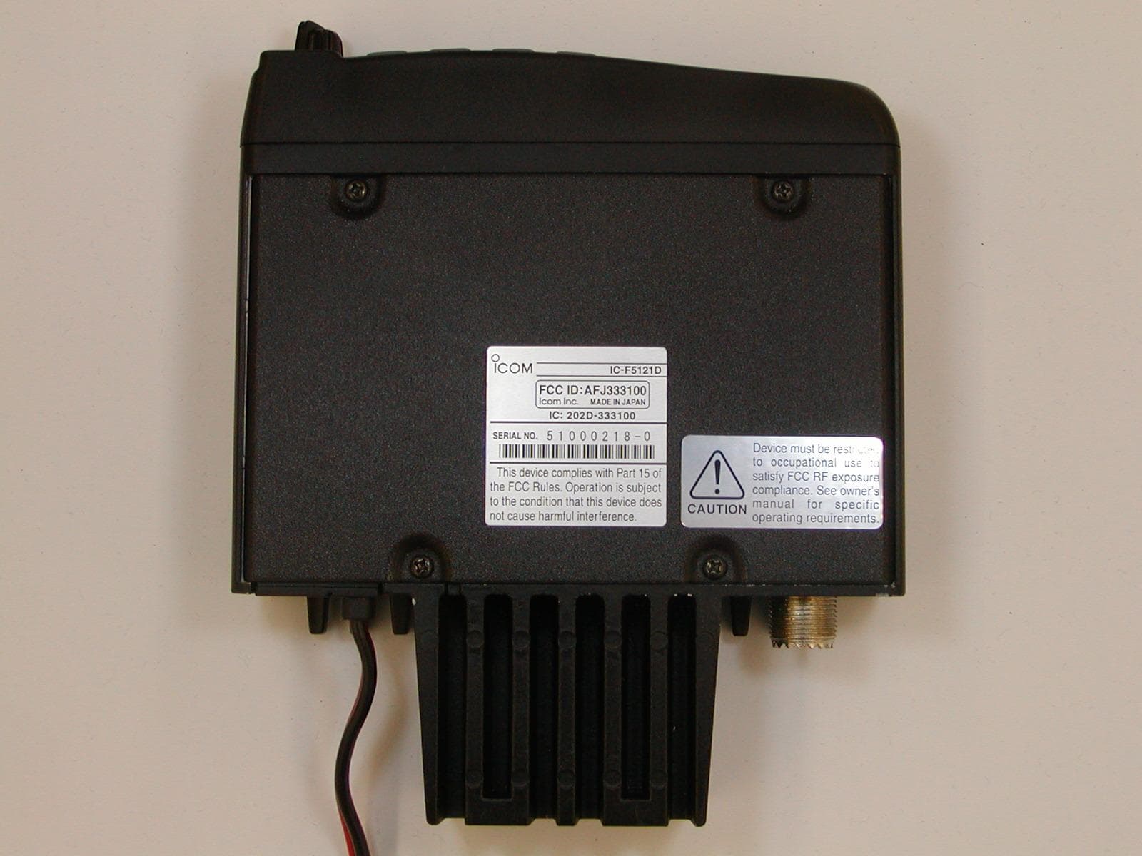
Click to zoom
Application Details
- Equipment Class
- TNB - Licensed Non-Broadcast Station Transmitter
- Date of Grant
- Dec 16, 2010
- Application Purpose
- Original Equipment
- Date of Application
- Dec 15, 2010
- Equipment Note
- VHF Mobile Transceiver
- Frequency Range
- 136.00000000 - 174.00000000
- Company
- ICOM Incorporated
- Country
- Japan
Documents & Files
Document Text
Text extracted from the exhibit documents filed with the FCC. Open a document above to read the original.
Users Manual
INSTRUCTION MANUAL VHF MOBILE TRANSCEIVERS iF5120D Series UHF MOBILE TRANSCEIVERS iF6120D Series Limited functions onlyLimited functions only i Icom, Icom Inc. and the Icom logo are registered trademarks of Icom Incor- porated (Japan) in Japan, the United States, the United Kingdom, Germany, France, Spain, Russia and/or other countries. All other products or brands are registered trademarks or trademarks of their respective holders. IMPORTANT READ ALL INSTRUCTIONS carefully and com- pletely before using the transceiver. SAVE THIS INSTRUCTION MANUAL — This instruction manual contains important operating instructions for the IC-F5121D, IC-F5123D VHF MOBILE TRANSCEIV- ERS and the IC-F6121D, F6123D UHF MOBILE TRANS- CEIVERS. EXPLICIT DEFINITIONS WORDDEFINITION RWARNING Personal injury, fire hazard or electric shock may occur. CAUTION Equipment damage may occur. NOTE If disregarded, inconvenience only. No risk of personal injury, fire or electric shock. FCC INFORMATION • FOR CLASS B UNINTENTIONAL RADIATORS: This equipment has been tested and found to comply with the limits for a Class B digital device, pursuant to part 15 of the FCC Rules. These limits are designed to provide reasonable protection against harmful interference in a residential instal- lation. This equipment generates, uses and can radiate radio frequency energy and, if not installed and used in accordance with the instructions, may cause harmful interference to radio communications. However, there is no guarantee that inter- ference will not occur in a particular installation. If this equip- ment does cause harmful interference to radio or television reception, which can be determined by turning the equipment off and on, the user is encouraged to try to correct the inter- ference by one or more of the following measures: • Reorient or relocate the receiving antenna. • Increase the separation between the equipment and re - ceiver. • Connect the equipment into an outlet on a circuit different from that to which the receiver is connected. • Consult the dealer or an experienced radio/TV technician for help. ii PRECAUTIONS RWARNING! NEVER connect the transceiver to an AC outlet. This may pose a fire hazard or result in an electric shock. RWARNING! NEVER connect the transceiver to a power source of more than 16 V DC such as a 24 V battery. This connection will ruin the transceiver. RWARNING! NEVER cut the DC power cable be- tween the DC plug and fuse holder. If an incorrect connection is made after cutting, the transceiver might be damaged. RWARNING! NEVER place the transceiver where normal operation of the vehicle may be hindered or where it could cause bodily injury. CAUTION! NEVER allow children to touch the trans- ceiver. CAUTION! NEVER expose the transceiver to rain, snow or any liquids. USE the specified microphone only. Other microphones have different pin assignments and may damage the transceiver. DO NOT use or place the transceiver in areas with tem- peratures below –30°C (–22°F) or above +60°C (+140°F), or in areas subject to direct sunlight, such as the dashboard. DO NOT operate the transceiver without running the ve- hicle’s engine. The vehicle’s battery will quickly run out when the transceiver transmits while the vehicle’s engine is OFF. DO NOT place the transceiver in excessively dusty envi- ronments. DO NOT place the transceiver against walls. This will ob- struct heat dissipation. DO NOT use chemical agents such as benzine or alcohol when cleaning, as they damage the transceiver surfaces. BE CAREFUL! The transceiver will become hot when operating continuously for long periods. For U.S.A. only CAUTION! Changes or modifications to this transceiver, not expressly approved by Icom Inc., could void your authority to operate this transceiver under FCC regulations. Approved Icom optional equipment is designed for optimal performance when used with an Icom transceiver. Icom is not responsible for the destruction or damage to an Icom transceiver in the event the Icom transceiver is used with equipment that is not manufactured or approved by Icom. iii TABLE OF CONTENTS IMPORTANT ..........................................................................i EXPLICIT DEFINITIONS .......................................................i FCC INFORMATION .............................................................i PRECAUTIONS ....................................................................ii TABLE OF CONTENTS .......................................................iii 1.ANEL DESCRI.TION.ANEL DESCRI.TION ................................................ 1–6 ■ Front panel ...................................................................1 ■ Function display ...........................................................2 ■ Programmable function keys ........................................3 2 BASIC O.ERATIONBASIC O.ERATION .................................................. 7–13 ■ Turning power ON ........................................................7 ■ Channel selection .........................................................7 ■ Call procedure ..............................................................8 ■ Receiving and transmitting ...........................................8 ■ User set mode ............................................................11 ■ Scrambler function .....................................................12 ■ Emergency transmission ............................................12 ■ Stun function ..............................................................12 ■ Priority A channel selection ........................................12 ■ MDC 1200 system operation ......................................13 3 CONNECTION AND MAINTENANCE ....................14–16 ■ Rear panel connection ...............................................14 ■ Supplied Accessories .................................................15 ■ Mounting the transceiver ............................................15 ■ Antenna ..........................…
Text truncated - open the document above for the full version.
Cover Letter(s)
December 13, 2010 Ultratech Engineering Labs, Inc. 3000 Bristol Circle Oakville, Ontario L6H 6G4 Subject: Equipment Authorization under FCC 47 CFR, Parts 2 and 90 (Subpart I) - Non-Broadcast Radio Transceivers Operating in the Frequency Band 136-174 MHz (25 KHz and 12.5 KHz Channel Spacings). Applicant: ICOM Incorporated Product: VHF Mobile Transceiver Model: IC-F5121D FCC ID: AFJ333100 Dear Sir/Madam, As appointed agent for ICOM Incorporated, we would like to submit the application to Federal Communications Commission for certification of the above product. Please review all files uploaded to your electronic filing site. If you have any queries, please do not hesitate to contact us by our TOLL FREE number: OUR TELEPHONE NO.: 1-877-747-6381 Yours truly, xutianlu Steven (Xu Tian) Lu Authorized Agent UltraTech Group of Labs FCC TCB & IC CB Ultratech’s Accreditations: 0685 FCC 91038 1309 46390-2049 NVLAP Lab Code 200093-0 SL2-IN-E-1119R Korea KCC-RRL CA2049 3000 Bristol Circle, Oakville, Ontario, Canada L6H 6G4 Tel.: (905) 829-1570 Fax.: (905) 829-8050 W ebsite: www.ultratech-labs.com
ID Label/Location Info
Serial Plate Layout
RF Exposure Info
4 SAFETY TRAINING INFORMATION 18 WARNING Your Icom radio generates RF electromagnetic en- ergy during transmit mode. This radio is designed for and classified as “Occupational Use Only”, meaning it must be used only during the course of employment by individuals aware of the hazards, and the ways to minimize such hazards. This radio is NOT intended for use by the “General Popula- tion” in an uncontrolled environment. • For compliance with FCC and Industry Canada RF Exposure Re- quirements, the transmitter antenna installation shall comply with the following two conditions: 1. The transmitter antenna gain shall not exceed 0 dBi. 2. IC-F5121D: The antenna is required to be located outside of a vehicle and kept at a distance of 45 centimeters or more between the trans- mitting antenna of this device and any persons during operation. For small vehicle as worst case, the antenna shall be located on the roof top at any place on the centre line along the vehicle in order to achieve 45 centimeters separation distance. In order to ensure this distance is met, the installation of the antenna must be mounted at least 45 centimeters away from the nearest edge of the vehicle in order to protect against exposure to bystanders. 2. IC-F6121D: The antenna is required to be located outside of a vehicle and kept at a distance of 37 centimeters or more between the trans- mitting antenna of this device and any persons during operation. For small vehicle as worst case, the antenna shall be located on the roof top at any place on the centre line along the vehicle in order to achieve 37 centimeters separation distance. In order to ensure this distance is met, the installation of the antenna must be mounted at least 37 centimeters away from the nearest edge of the vehicle in order to protect against exposure to bystanders. 3. IC-F5121D: Transmit only when people outside the vehicle are at least the recommended minimum distance of 100 centimeters away from the properly installed antenna. This separation distance will en- sure that there is sufficient distance from a properly installed externally-mounted antenna to satisfy the RF exposure require- ments in the applicable RF exposure compliance standards. 3. IC-F6121D: Transmit only when people outside the vehicle are at least the recommended minimum distance of 82 centimeters away from the properly installed antenna. This separation distance will en- sure that there is sufficient distance from a properly installed externally-mounted antenna to satisfy the RF exposure require- ments in the applicable RF exposure compliance standards. SAFETY TRAINING INFORMATION 4 1 2 16 15 14 13 12 11 10 9 8 7 6 5 4 19 3 CAUTION To ensure that your exposure to RF electromag- netic energy is within the FCC allowable limits for occupational use, always adhere to the following guidelines: • DO NOT operate the radio without a proper antenna attached, as this may damage the radio and may also cause you to exceed FCC RF exposure limits. A proper antenna is the antenna supplied with this radio by the manufacturer or an antenna specifically authorized by the manufacturer for use with this radio. • DO NOT transmit for more than 50% of total radio use time (“50% duty cycle”). Transmitting more than 50% of the time can cause FCC RF exposure compliance requirements to be exceeded. The radio is transmitting when the “transmit indicator” appears on the LCD. You can cause the radio to transmit by pressing the “PTT” switch. Electromagnetic Interference/Compatibility During transmissions, your Icom radio generates RF energy that can possibly cause interference with other devices or systems. To avoid such interference, turn OFF the radio in areas where signs are posted to do so. DO NOT operate the transmitter in areas that are sensitive to electromagnetic radiation such as hospitals, aircraft, and blasting sites. FCC PARTS 2 & 90, SUBPART I, NON-BROADCAST RADIO TRANSCEIVERS Page 9 VHF Mobile Transceiver, Model IC-F5121D FCC ID: AFJ333100 ULTRATECH GROUP OF LABS File #: ICOM-262F90 3000 Bristol Circle, Oakville, Ontario, Canada L6H 6G4 December 13, 2010 Tel. #: 905-829-1570, Fax. #: 905-829-8050, Email: [email protected] , Website: http://www.ultratech-labs.com All test results contained in this engineering test report are traceable to National Institute of Standards and Technology (NIST) 5.2. RF EXPOSURE REQUIRMENTS [§§ 1.1310 & 2.1091] The criteria listed in the following table shall be used to evaluate the environmental impact of human exposure to radio- frequency (RF) radiation. FCC 47 CFR § 1.1310: 5.2.1. Method of Measurements Refer to Sections 1.1310, 2.1091 In order to demonstrate compliance with MPE requirements (see Section 2.1091), the following information is typically needed: (1) Calculation that estimates the minimum separation distance (20 cm or more) between an antenna and persons required to satisfy power density limits defined for free space. (2) Antenna installation and device operating instructions for installers (professional/unskilled users), and the parties responsible for ensuring compliance with the RF exposure requirement (3) Any caution statements and/or warning labels that are necessary in order to comply with the exposure limits (4) Any other RF exposure related issues that may affect MPE compliance FCC PARTS 2 & 90, SUBPART I, NON-BROADCAST RADIO TRANSCEIVERS Page 10 VHF Mobile Transceiver, Model IC-F5121D FCC ID: AFJ333100 ULTRATECH GROUP OF LABS File #: ICOM-262F90 3000 Bristol Circle, Oakville, Ontario, Canada L6H 6G4 December 13, 2010 Tel. #: 905-829-1570, Fax. #: 905-829-8050, Email: [email protected] , Website: http://www.ultratech-labs.com All test results contained in this engineering test report are traceable to National Institute of Standards and Technology (NIST) Calculation Method of RF Safety Distance: 22 44r EIRP r GP S Where: P: power input to the antenna in mW EIRP: Equivalent (effective) isotropic radiated power S: power density …
Text truncated - open the document above for the full version.
Test Report
VHF Mobile Transceiver Model No.: IC-F5121D FCC ID: AFJ333100 Applicant: ICOM Incorporated 1-1-32, Kamiminami, Hirano-ku Osaka Japan, 547-0003 Tested in Accordance With Federal Communications Commission (FCC) 47 CFR, Parts 2 and 90 (Subpart I) UltraTech's File No.: ICOM-262F90 This Test report is Issued under the Authority of Tri M. Luu, Professional Engineer, Vice President of Engineering UltraTech Group of Labs Date: December 13, 2010 Report Prepared by: Steven (Xu Tian) Lu Issued Date: December 13, 2010 Tested by: Wayne Wu, RFI/EMI Technician Test Dates: Nov. 03 – Dec. 10, 2010 The results in this Test Report apply only to the sample(s) tested, and the sample tested is randomly selected. This report must not be used by the client to claim product endorsement by NVLAP or any agency of the US Government. UltraTech Group of Labs 3000 Bristol Circle, Oakville, Ontario, Canada, L6H 6G4 Tel.: (905) 829-1570 Fax.: (905) 829-8050 Website: www.ultratech-labs.com , Email: [email protected] , Email: [email protected] FCC Korea KCC-RRL 91038 1309 46390-2049 NVLAP Lab Code 200093-0 SL2-IN-E-1119R CA2049 FCC PARTS 2 & 90, SUBPART I, NON-BROADCAST RADIO TRANSCEIVERS Contents i VHF Mobile Transceiver, Model IC-F5121D FCC ID: AFJ333100 ULTRATECH GROUP OF LABS File #: ICOM-262F90 3000 Bristol Circle, Oakville, Ontario, Canada L6H 6G4 December 13, 2010 Tel. #: 905-829-1570, Fax. #: 905-829-8050, Email: [email protected] , Website: http://www.ultratech-labs.com All test results contained in this engineering test report are traceable to National Institute of Standards and Technology (NIST) TABLE OF CONTENTS EXHIBIT 1. INTRODUCTION ............................................................................................................................................ 1 1.1. SCOPE ............................................................................................................................................................................ 1 1.2. RELATED SUBMITTAL(S)/GRANT(S) ...................................................................................................................... 1 1.3. NORMATIVE REFERENCES ....................................................................................................................................... 1 EXHIBIT 2. PERFORMANCE ASSESSMENT .................................................................................................................. 2 2.1. CLIENT INFORMATION ............................................................................................................................................. 2 2.2. EQUIPMENT UNDER TEST (EUT) INFORMATION ................................................................................................. 2 2.3. EUT’S TECHNICAL SPECIFICATIONS ..................................................................................................................... 3 2.4. LIST OF EUT’S PORTS ................................................................................................................................................. 4 2.5. GENERAL TEST SETUP ..................................................................................................................................................... 4 EXHIBIT 3. EUT OPERATING CONDITIONS AND CONFIGURATIONS DURING TESTS ................................... 5 3.1. CLIMATE TEST CONDITIONS ................................................................................................................................... 5 3.2. OPERATIONAL TEST CONDITIONS & ARRANGEMENT FOR TEST SIGNALS .................................................. 5 EXHIBIT 4. SUMMARY OF TEST RESULTS .................................................................................................................. 6 4.1. LOCATION OF TESTS ................................................................................................................................................. 6 4.2. APPLICABILITY & SUMMARY OF EMISSION TEST RESULTS ............................................................................ 6 4.3. MODIFICATIONS INCORPORATED IN THE EUT FOR COMPLIANCE PURPOSES ............................................ 6 EXHIBIT 5. TEST DATA ...................................................................................................................................................... 7 5.1. RF POWER OUTPUT [§ 2.1046 & 90.205] ................................................................................................................... 7 5.2. RF EXPOSURE REQUIRMENTS [§§ 1.1310 & 2.1091] .............................................................................................. 9 5.3. AUDIO FREQUENCY RESPONSE [§ 2.1047(A) & 90.242(B)(8)] ............................................................................. 11 5.4. MODULATION LIMITING [§ 2.1047 (B) & 90.210] .................................................................................................. 17 5.5. OCCUPIED BANDWIDTH & EMISSION MASK [§§ 2.1049, 90.209 & 90.210] ...................................................... 22 5.6. TRANSMITTER ANTENNA POWER SPURIOUS/HARMONIC CONDUCTED EMISSIONS [§2.1051, 2.1057 & 90.210] ...................................................................................................................................................................................... 60 5.7. TRANSMITTER SPURIOUS/HARMONIC RADIATED EMISSIONS [§ 2.1053, 2.1057 & 90.210] ....................... 78 5.8. FREQUENCY STABILITY [§ 2.1055 & 90.213] ........................................................................................................ 84 5.9. TRANSIENT FREQUENCY BEHAVIOR [§ 90.214] ................................................................................................. 86 EXHIBIT 6. TEST INSTRUMENTS & MEASUREMENT UNCERTAINTY (K=2, 95% CONFIDENCE LEVEL) 94 RADIATED EMISSION MEASUREMENT UNCERTAINTY ....................................................…
Text truncated - open the document above for the full version.
Test Setup Photos
ANNEX 1 - TEST SETUP PHOTOGRAPHS Photo # 1 ICOM Incorporated VHF Mobile Transceiver, M/N: IC-F5121D FCC ID: AFJ333100, IC: 202D-333100 Plot #1: Radiated Emission Test Setup ANNEX 1 - TEST SETUP PHOTOGRAPHS Photo # 2 ICOM Incorporated VHF Mobile Transceiver, M/N: IC-F5121D FCC ID: AFJ333100, IC: 202D-333100 Plot #2: Radiated Emission Test Setup
Contact Information
Applicant
Atsushi Tomiyama(General Manager)
Technical Contact
UltraTech Engineering Labs Inc.Steven Lu
[email protected]905-829-1570
3000 Bristol Circle · Oakville, ON · Canada
Test Firm
UltraTech Engineering Labs Inc.Tri Luu
Technical Specifications
| # | Rule Parts | Frequency Range | Power Output | Emission | Tolerance |
|---|---|---|---|---|---|
| 8 | 9 | 136 MHz - 174 MHz | 5 W | 4K10F1D | 2 ppm |
Other Applications from ICOM Incorporated

AFJ460100
Aug 31, 2026VHF DSC Marine Radio
Equipment Class
TNB - Licensed Non-Broadcast Station Transmitter
AFJ453700
Jul 23, 2026Mobile Transceiver
Equipment Class
DTS - Digital Transmission System
AFJ452000
Jun 02, 2026VHF DIGITAL TRANSCEIVER
Equipment Class
TNF - Licensed Non-Broadcast Transmitter Held to Face
AFJ452100
May 12, 2026UHF DIGITAL TRANSCEIVER
Equipment Class
TNF - Licensed Non-Broadcast Transmitter Held to Face
AFJ444500
Sep 12, 2024Scanning Receiver
Equipment Class
CSR - Scanning Receiver