AFJ339000VHF/UHF Transceiver
ICOM Incorporated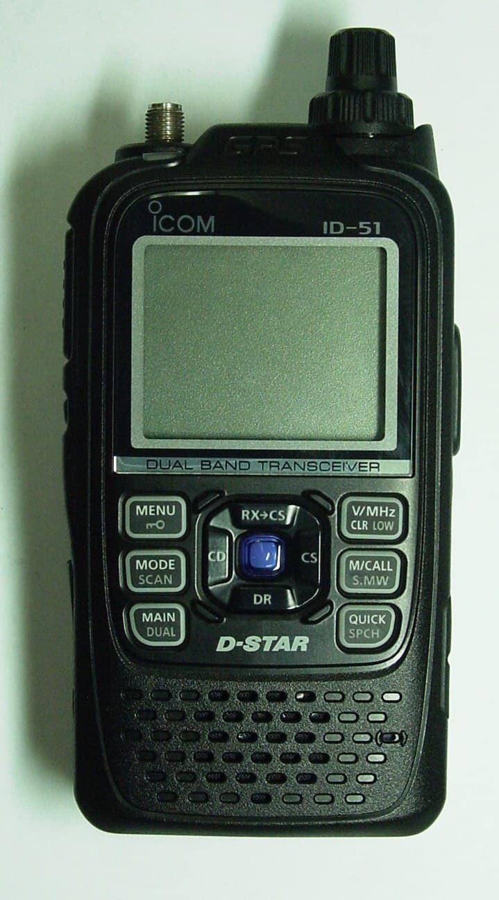
Click to zoom
Application Details
- Equipment Class
- CSR - Scanning Receiver
- Date of Grant
- Jan 14, 2013
- Application Purpose
- Original Equipment
- Date of Application
- Jan 14, 2013
- Equipment Note
- VHF/UHF Transceiver
- Frequency Range
- 380.00000000 - 479.00000000
- Company
- ICOM Incorporated
- Country
- Japan
Documents & Files
Document Text
Text extracted from the exhibit documents filed with the FCC. Open a document above to read the original.
Users Manual
This device complies with Part 15 of the FCC Rules. Operation is subject to the following two conditions: (1) this device may not cause harmful interference, and (2) this device must accept any interference received, including interference that may cause undesired operation. WARNING: MODIFICATION OF THIS DEVICE TO RECEIVE CEL- LULAR RADIOTELEPHONE SERVICE SIGNALS IS PROHIBITED UNDER FCC RULES AND FEDERAL LAW. BASIC INSTRUCTIONS New2001 ID-51A VHF/UHF TRANSCEIVER ID-51E VHF/UHF TRANSCEIVER L e t ’ s b e g i n u s i n g D - S T A R ! You can easily begin using D-STAR repeaters! 1 New2001New2001 UNIQUE FEATURES OF D-STAR Easy to QSO to the world ● Easy call sign entry with ● the Repeater list or TX/RX History Call Sign Capture key ● makes call sign capture easy. Easy Desti- nation (To) setting! Worldwide communication!! This key makes call sign capture easy! PREPARATION New2001 PREPARATION IMPORTANT! Before starting D-STAR, entering and registering your call sign (MY) are needed, as described below. STEP 1 Entering your call sign (MY) into the transceiver. STEP 2 Registering your call sign (MY) to a gateway repeater. You have completed the steps!! STEP 1 Enter your call sign into the transceiver Example: Enter “JA3YUA” as your own call sign into the MY call sign memory [MY1]. Hold down q[] for 1 second to turn ON the power. • Hold down [] for 1 second to turn OFF power. • After the opening message and power source voltage are dis- played, the operating frequency appears. Push [MENU] w. • The MENU screen is displayed. Push D-pad( e) to select the root item (“My Station”), and then push D-pad(Ent). D-pad (�) (Ent) Push D-pad( r) to select “My Call Sign,” and then push D- pad(Ent). • The MY CALL SIGN screen is displayed. MENU screen Go to step t Continued on the next page This is page 2. [] New2001 3 PREPARATION New2001 Push D-pad( t) to select MY call sign memory channel “1” ([MY1]). D-pad (�) (Ent) Push [QUICK] y, and then push D-pad() to select “Edit.” Then, push D-pad(Ent) to enter the call sign edit mode. • A cursor appears and blinks. Rotate [DIAL] to select the u first digit. (Example: J) • A to Z, 0 to 9, / and (Space) are selectable. • Cursor move: Push D-pad(). • Delete: Push [CLR]. • Insert: Move cursor, then rotate [DIAL]. • Rotate [DIAL] counterclockwise to enter a space. Push iD-pad() to move the cursor to the second digit. NOTE: Your call sign must match the call sign registered to your gateway repeater. Repeat steps ou and i to enter your own call sign of up to 8 characters, including spaces. ( For example: First J, then A, then 3, then Y, then U, then A) !0 Push D-pad(Ent) to set the call sign. • See next page if you enter a note. !1 Push D-pad(Ent) again to save and return to the MY CALL SIGN screen. • Two beeps sound. !2 Push [MENU] to exit the MENU screen. Edit mode Beeps Completed Go to step o [DIAL] Selects/exits the MENU screen Moves the cursor Selects Deletes Shows the QUICK MENU Keys used for input New2001 4 PREPARATION Access the repeater p. 17 How to use the RX History p. 21 Capturing a call sign p. 25 Making a Local area call p. 27 Making a Gateway call p. 29 Calling a destination station p. 31 Making a Simplex call p. 33 If needed, ask the gateway repeater administrator for call sign registration instructions. To use a repeater gateway, you must register your call sign with a gateway repeater, usually one near your home location. RX TX Now, you can begin using D-STAR! New users start here! In the next step, register your call sign to a gateway repeater. I can begin using D-STAR!! Completed!! Convenient! ✓ If necessary, enter a note of up to 4 characters, such as the model of the transceiver, name, area name, and so on, after your call sign. Push qD-pad() until the cursor moves to the right of the “/”. Repeat steps wu and i to the left to enter a desired 4 character note. (Example: ID51) STEP 2 Register your call sign to a gateway repeater Troubleshooting p. 35 5 New2001New2001 TABLE OF CONTENTS New2001 D-STAR Operation D-STAR Operation Answer the questions, and figure out your operating steps! Start Confirm you can access your local repeater? YES Go to page 17 NO Reply to a call? YES NO How to easily reply using the call- ing station’s call sign? Call Sign Capture key Go to page 25 RX History Go to page 21 Making a call in your local area? (Local area call) YES Go to page 27 NO Use a repeater? YES NO Go to page 33 Making a call to another area? (Gateway call) To a specific station To anyone Go to page 29 NOTE: This chart may not apply to your specific environment. New2001 6 TABLE OF CONTENTS New2001 Other functionsD-STAR Operation D-STAR Operation Saving settings Go to page 37 Learn about the new built in functions Go to page 47 Troubleshooting Go to page 35 Checking your position using GPS Go to page 43 Recording a QSO conversation Go to page 39 Checking your route using the GPS logger function Go to page 45 The destination call sign is al- ready programmed? YES Go to page 31 NO Go to section ? of the CD Ad- vanced Instruction PDF for call sign programming. Then, Go to page 31 of this manual. • If you have received a call from the station before, the call sign may be in RX History. (p. 21) 7 TABLE OF CONTENTS New2001 UNIQUE FEATURES OF D-STAR ..................... 1 PREPARATION ............................................ 2–16 Enter your call sign into the transceiver ................................ 2 Register your call sign to a gateway repeater ....................... 4 TABLE OF CONTENTS ........................................................ 5 FOREWORD ........................................................................9 FEATURES ...........................................................................9 EXPLICIT DEFINITIONS .................................................... 10 IMPORTANT ....................................................................... 10 SUPPLIED ACCESSORIES ............................................... 10 ABOUT THE SUP…
Text truncated - open the document above for the full version.
Cover Letter(s)
UltraTech Group of Labs FCC TCB & IC CB Ultratech’s Accreditations: 0685 FCC 91038 1309 46390-2049 NvLap Lab Code 200093-0 SL2-IN-E-1119R Korea KCC-RRL CA2049 3000 Bristol Circle, Oakville, Ontario, Canada L6H 6G4 Tel.: (905) 829-1570 Fax.: (905) 829-8050 Website: www.ultratech-labs.com Email: [email protected] January 9, 2013 Ultratech Engineering Labs, Inc. 3000 Bristol Circle Oakville, Ontario L6H 6G4 Subject: Certification Testing in Accordance with FCC CFR 47, Part 15, Subpart B - Scanning Receiver Applicant: ICOM Incorporated Product: VHF/UHF Dual Band Transceiver Model: ID-51A FCC ID: AFJ339000 Dear Sir/Madam: As appointed agent for ICOM Incorporated, we submit the application for certification of the above product. Please review all files uploaded to your electronic filing site. If you have any queries, please do not hesitate to contact us: Yours truly, Dharmajit Solanki Dharmajit Solanki Authorized Agent
Test Report
VHF/UHF Dual Band Transceiver Model No.: ID-51A FCC ID: AFJ339000 Applicant: ICOM Incorporated 1-1-32, Kamiminami, Hirano-ku Osaka, Japan, 547-0003 Tested in Accordance With Federal Communications Commission (FCC) 47 CFR, Part 15, Subpart B, Scanning Receivers UltraTech's File No.: ICOM-320Q_FCC15.121 This Test report is Issued under the Authority of Tri M. Luu, BASc Vice President of Engineering UltraTech Group of Labs Date: January 9, 2013 Report Prepared by: Santhosh Fernandez Issued Date: January 9, 2013 Tested by: Wei Wu and Hien Luu Test Dates: December 18, 19, 22 and 24, 2012 and January 9, 2013 The results in this Test Report apply only to the sample(s) tested, and the sample tested is randomly selected. This report must not be used by the client to claim product endorsement by NVLAP or any agency of the US Government. UltraTech 3000 Bristol Circle, Oakville, Ontario, Canada, L6H 6G4 Tel.: (905) 829-1570 Fax.: (905) 829-8050 Website: www.ultratech-labs.com , Email: [email protected], Email: [email protected] FCC Korea KCC-RRL 91038 1309 46390-2049 NvLap Lab Code 200093-0 SL2-IN-E-1119R CA2049 FCC Part 15, Subpart B, Section 15.121 Contents i VHF/UHF Dual Band Transceiver, M/N: ID-51A FCC ID: AFJ339000 ULTRATECH GROUP OF LABS File #: ICOM-320Q_FCC15.121 3000 Bristol Circle, Oakville, Ontario, Canada L6H 6G4 January 9, 2013 Tel. #: 905-829-1570, Fax. #: 905-829-8050, Email: [email protected] , Website: http://www.ultratech-labs.com All test results contained in this engineering test report are traceable to National Institute of Standards and Technology (NIST) TABLE OF CONTENTS EXHIBIT 1. INTRODUCTION ......................................................................................................................................... 1 1.1. SCOPE......................................................................................................................................................................... 1 1.2. RELATED SUBMITTAL(S)/GRANT(S) .................................................................................................................. 1 1.3. NORMATIVE REFERENCES ................................................................................................................................... 1 EXHIBIT 2. PERFORMANCE ASSESSMENT .............................................................................................................. 2 2.1. CLIENT INFORMATION .......................................................................................................................................... 2 2.2. EQUIPMENT UNDER TEST (EUT) INFORMATION ............................................................................................ 2 2.3. EUT’S TECHNICAL SPECIFICATIONS ................................................................................................................. 3 2.4. LIST OF EUT’S PORTS............................................................................................................................................. 3 2.5. ANCILLARY EQUIPMENT ...................................................................................................................................... 3 EXHIBIT 3. EUT OPERATING CONDITIONS AND CONFIGURATIONS DURING TESTS ............................... 4 3.1. OPERATIONAL TEST CONDITIONS & ARRANGEMENT FOR TEST SIGNALS............................................. 4 EXHIBIT 4. SUMMARY OF TEST RESULTS ............................................................................................................... 5 4.1. LOCATION OF TESTS.............................................................................................................................................. 5 4.2. APPLICABILITY & SUMMARY OF EMC EMISSION TEST RESULTS ............................................................. 5 4.3. MODIFICATIONS REQUIRED FOR COMPLIANCE............................................................................................. 5 EXHIBIT 5. MEASUREMENTS, EXAMINATIONS & TEST DATA FOR EMC EMISSIONS............................... 6 5.1. TEST PROCEDURES................................................................................................................................................. 6 5.2. MEASUREMENT UNCERTAINTIES ...................................................................................................................... 6 5.3. MEASUREMENT EQUIPMENT USED ................................................................................................................... 6 5.4. POWER LINE CONDUCTED EMISSIONS [§ 15.107(A)] ...................................................................................... 7 5.5. RECEIVER ANTENNA POWER SPURIOUS/HARMONIC CONDUCTED EMISSIONS [§15.111(A)] ........... 10 5.6. SPURIOUS/HARMONIC RADIATED EMISSIONS FROM RECEIVER AND CLASS B UNINTENTIONAL RADIATORS (DIGITAL DEVICES) [§ 15.109(A)] ............................................................................................... 18 5.7. REQUIREMENTS FOR SCANNING RECEIVERS [§ 15.121].............................................................................. 22 5.8. SCANNING RECEIVERS CELLULAR BAND REJECTION [§ 15.121(B)] ........................................................ 25 EXHIBIT 6. TEST EQUIPMENTS LIST ....................................................................................................................... 27 EXHIBIT 7. MEASUREMENT UNCERTAINTY.........................................................................................................28 7.1. LINE CONDUCTED EMISSION MEASUREMENT UNCERTAINTY ................................................................ 28 7.2. RADIATED EMISSION MEASUREMENT UNCERTAINTY .............................................................................. 28 FCC Part 15, Subpart B, Section 15.121 Page 1 VHF/UHF Dual Band Transceiver, M/N: ID-51A FCC ID: AFJ339000 ULTRATECH GROUP OF LABS File #: ICOM-320Q_FCC15.121 300…
Text truncated - open the document above for the full version.
Test Setup Photos
ANNEX 1 – TEST SETUP PHOTOS Icom Incorporated UHF Transceiver, Model ID-51A FCC ID: AFJ339000, IC: 202D-339000 A1 - 1 AC Power-line Conducted Emission ANNEX 1 – TEST SETUP PHOTOS Icom Incorporated UHF Transceiver, Model ID-51A FCC ID: AFJ339000, IC: 202D-339000 A1 - 2 AC Power-line Conducted Emission ANNEX 1 – TEST SETUP PHOTOS Icom Incorporated UHF Transceiver, Model ID-51A FCC ID: AFJ339000, IC: 202D-339000 A1 - 3 Radiated Emission at 3m Distance ANNEX 1 – TEST SETUP PHOTOS Icom Incorporated UHF Transceiver, Model ID-51A FCC ID: AFJ339000, IC: 202D-339000 A1 - 4 Radiated Emission at 3m Distance ANNEX 1 – TEST SETUP PHOTOS Icom Incorporated UHF Transceiver, Model ID-51A FCC ID: AFJ339000, IC: 202D-339000 A1 - 5 Radiated Emission at 3m Distance ANNEX 1 – TEST SETUP PHOTOS Icom Incorporated UHF Transceiver, Model ID-51A FCC ID: AFJ339000, IC: 202D-339000 A1 - 6 Radiated Emission at 3m Distance
Contact Information
Applicant
Atsushi Tomiyama(General Manager)
Test Firm
UltraTech Engineering Labs Inc.Tri Luu
Technical Specifications
| # | Rule Parts | Frequency Range | Power Output |
|---|---|---|---|
| 2 | 15B | 380 MHz - 479 MHz | - |
Other Applications from ICOM Incorporated

AFJ460100
Aug 31, 2026VHF DSC Marine Radio
Equipment Class
TNB - Licensed Non-Broadcast Station Transmitter
AFJ453700
Jul 23, 2026Mobile Transceiver
Equipment Class
DTS - Digital Transmission System
AFJ452000
Jun 02, 2026VHF DIGITAL TRANSCEIVER
Equipment Class
TNF - Licensed Non-Broadcast Transmitter Held to Face
AFJ452100
May 12, 2026UHF DIGITAL TRANSCEIVER
Equipment Class
TNF - Licensed Non-Broadcast Transmitter Held to Face
AFJ444500
Sep 12, 2024Scanning Receiver
Equipment Class
CSR - Scanning Receiver