AFJ369402UHF Transceiver
ICOM Incorporated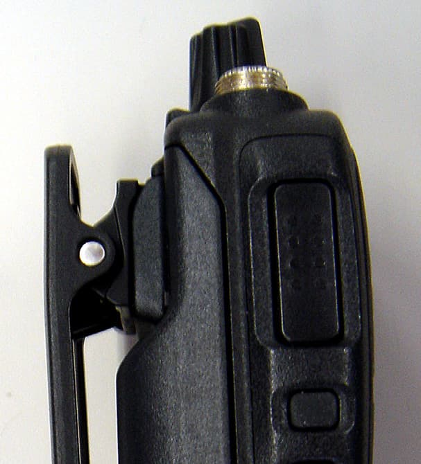
Click to zoom
Application Details
- Equipment Class
- TNF - Licensed Non-Broadcast Transmitter Held to Face
- Date of Grant
- Nov 17, 2015
- Application Purpose
- Original Equipment
- Date of Application
- Nov 17, 2015
- Equipment Note
- UHF Transceiver
- Frequency Range
- 450.00000000 - 512.00000000
- Company
- ICOM Incorporated
- Country
- Japan
Documents & Files
Document Text
Text extracted from the exhibit documents filed with the FCC. Open a document above to read the original.
Users Manual
OPERATING GUIDE iF1000D series VHF DIGITAL TRANSCEIVERS iF2000D series UHF DIGITAL TRANSCEIVERS The photo shows the VHF transceiver. i TABLE OF CONTENTS Icom, Icom Inc. and the Icom logo are registered trademarks of Icom Incorporated (Japan) in Japan, the United States, the United Kingdom, Germany, France, Spain, Russia, Aus- tralia, New Zealand, and/or other countries. All other products or brands are registered trademarks or trademarks of their respective holders. 1. PANEL DESCRIPTION Front, top and side panels ...........................1-2 LED indicator ..........................................1- 3 Programmable function keys .....................1- 4 2. BASIC OPERATION Selecting a channel .................................2-2 Receiving and transmitting ........................2-3 Transmitting notes .................................2-3 Receiving a Stun, Kill, and Revive call ......2-3 Emergency call .......................................2-4 About other Emergency calls .....................2-5 Lone Worker Emergency call ..................2-5 Man Down Emergency call .....................2-5 Motion Detection Emergency call ............2-5 3. NXDN™ OPERATION NXDN™ operation ....................................3-2 Conventional mode ..............................3-2 Trunking mode ....................................3-2 Receiving a call .......................................3-3 Receiving a Call Alert ...........................3-3 Receiving a Stun, Kill, and Revive call ......3-3 Receiving a Remote Monitor or Radio Check call 3-3 Receiving a Status call ...........................3-3 Transmitting a call ....................................3-4 Transmitting a Call Alert ........................3-4 Transmitting an Emergency call ...............3-4 Transmitting a Status call ........................3-4 About other Emergency calls .....................3-5 Lone Worker Emergency call ..................3-5 Man Down Emergency call .....................3-5 Motion Detection Emergency call ............3-5 Encryption function .................................3-6 4. MDC 1200 SYSTEM OPERATION MDC 1200 system operation .....................4-2 Receiving a call .......................................4-3 Receiving a PTT ID ..............................4-3 Receiving an Emergency call ..................4-3 Receiving a Stun or Revive call ...............4-3 Transmitting a call ....................................4-4 Transmitting a PTT ID ...........................4-4 Transmitting an Emergency call ...............4-4 5. USER SETTINGS Setting the Beep function ...........................5-2 Setting the Beep level ..............................5-3 Setting the Ringer level ..............................5-4 Setting the microphone gain ........................5-5 Setting the squelch level ...........................5-6 Setting the VOX function ...........................5-7 Setting the VOX gain .................................5-8 1-1 Section 1 PANEL DESCRIPTION Front, top and side panels ......................................................1-2 LED indicator ...........................................................................1-3 Programmable function keys .................................................1- 4 1 PANEL DESCRIPTION 1-2 ROTARY SELECTOR Rotate to select the preset memory channels. VOLUME CONTROL [VOL] Rotate to turn the power ON or OFF and to adjust the audio level. DEALER-ASSIGNABLE KEY [Emer] A desired function can be preset by your dealer. SPEAKER-MICROPHONE JACK Connect an optional equipment. NOTE: After turning OFF the transceiver, connect or disconnect the optional equipment. Jack cover NOTE: Attach the jack cover when optional equipment is not used. ROTARY SELECTOR VOLUME CONTROL [VOL] [Emer] Speaker [Lower] [Upper] PTT SWITCH [PTT] LED INDICATOR Microphone ANTENNA CONNECTOR SPEAKER- MICROPHONE JACK Front, top and side panels DEALER-ASSIGNABLE KEYS [Upper] or [Lower] Desired functions can be independently preset by your dealer. PTT SWITCH [PTT] Hold down to transmit, release to receive. LED INDICATOR (p. 1-3) Lights red while transmitting.  Lights green while receiving a signal, or when the  squelch is open. Lights or blinks orange when the matching 2-Tone  or 5-Tone is received, depending on the presetting. You should charge the battery when the indicator  slowly blinks. You must charge the battery when the indicator  blinks fast. ANTENNA CONNECTOR Connects the supplied antenna. Detaching and attaching the jack cover Attaching: Attach the jack cover (q), then tighten the screws (w). Detaching: Remove the screws ( z), then detach the jack cover (x). x q w w z z Attaching: Attach the jack cover (q), then tighten the screws (w). Detaching: Remove the screws ( z), then detach the jack cover (x). x q w w z z 1 PANEL DESCRIPTION 1-3 LED indicator The LED indicator indicates the status of various parameters of the transceiver as follows: (Reference: R=Red, G=Green, O=Orange) Cloning (reading or writing data)• GGGGGGGG Cloning Error (if cloning fails)• RGRGRGRGRGRGRGRG Inh, Blank CH, Unlocked • (when you cannot use the channel) RORORORORORORORO TX Low Battery 2 (while transmitting)• RRRRRRRRRRRR TX Low Battery 1 (while transmitting)• RRRRRRRRRRRRRR Call LED=ON • (when receiving a matching 2-Tone or 5-Tone) OO Call LED=Blink • (when receiving a matching 2-Tone or 5-Tone) OO Scanning• GG Low Battery 2 (You must charge the battery.)• GGGG Low Battery 1 (You should charge the battery.)• GG Calling• OOOOOO Audible• OO When turning ON the power• ROGROG Lockout, TX Inh, TOT • (when transmit is inhibited) RRROOO Successful• OOOOGGGG Failed, Error• OOOORRRR Emergency, Siren• ROGROGROGROG Transmitting• RRRRRRRRRRRRRRRR Receiving• GGGGGGGGGGGGGGGG The following LED indicator patterns are repetitive. One cycle is approximately two seconds. The following LED indicator patterns light only once. 1 PANEL DESCRIPTION 1-4 Programmable function keys The following fu…
Text truncated - open the document above for the full version.
Users Manual
About the LED Indicator D • Lights red while transmitting. • Lights green while receiving a signal, or when the squelch is open. • Lights or blinks orange when the matched 2-Tone or 5-Tone is received, depending on the presetting. • You should charge the battery when the indicator slowly blinks green. • You must charge the battery when the indicator blinks green fast. About the Speaker microphone jack D CAUTION: Only when the jack cover or the optional HM-168LWP, HM-171GPW, HS-94LWP, or HS-95LWP is attached, the transceiver meets IP67 requirements for dust-tight and waterproof protection. Thank you for purchasing the IC-F1000D series v h f d i g i t a l t r a n s c e i v e r s or IC-F2000D series u h f d i g i t a l t r a n s c e i v e r s. READ ALL INSTRUCTIONS carefully and completely before using the transceiver. INSTRUCTIONS PANEL DESCRIPTION A-7206H-2EX Printed in Japan © 2015 Icom Inc. 1-1-32 Kamiminami, Hirano-ku, Osaka 547-0003, Japan SUPPLIED ACCESSORIES q w e r t Battery pack* q Battery charger* (BC-213) w Belt clip (MB-133) e Power adapter* (for the battery charger) r Flexible antenna* t * Not supplied, or the shape is different, depending on the transceiver version. VHF DIGITAL TRANSCEIVERS Iç-F2000D series UHF DIGITAL TRANSCEIVERS Iç-F1000D series BATTERY PACKS D BP-278/BP-279/BP-280• b a t t e r y p a c k Battery packVoltageCapacityBattery life* BP-2787.2 V 1130 mAh (minimum) 1190 mAh (typical) 9 hours BP-2797.2 V 1485 mAh (minimum) 1570 mAh (typical) 12 hours BP-280 7.2 V 2280 mAh (minimum) 2400 mhA (typical) 18 hours * When the power save function is turned ON, and the operating periods are calculated under the following conditions. TX : RX : standby = 5 : 5 : 90 CHARGERS D BC-213 • d e s k t o p c h a r g e r + BC-123S a c a d a p t e r To rapid charge a single battery pack. BC-214 • m u l t i c h a r g e r + BC-157S a c a d a p t e r To rapid charge up to 6 battery packs. DC CABLES D CP-23L• c i g a r e t t e l i g h t e r c a b l e Use when charging the battery pack from a 12 V cigarette lighter socket. (Use with the BC-213) OPC-656 • d c p o w e r c a b l e Use with a 13.8 V power source instead of the power adapter. (Use with the BC-214) ANTENNAS D FA-SC25V/ FA-SC55V/ FA-SC62V/ FA-SC63V • v h f a n t e n n a s FA-SC25V: 136–150 MHz FA-SC55V: 150–174 MHz FA-SC62V: 150–160 MHz FA-SC63V: 155–165 MHz FA-SC26VS/FA-SC27VS/FA-SC56VS/FA-SC57VS • v h f s t u b b y a n t e n n a s FA-SC26VS: 136–144 MHz FA-SC27VS: 142–150 MHz FA-SC56VS: 150–162 MHz FA-SC57VS: 160–174 MHz FA-SC61VC • v h f c u t a n t e n n a FA-SC61VC: 136–174 MHz FA-SC25U/FA-SC57U/FA-SC72U/FA-SC73US • u h f a n t e n n a s FA-SC25U: 400–430 MHz FA-SC57U: 430–470 MHz FA-SC72U: 470–520 MHz FA-SC73US: 450–490 MHz FA-SC26US • u h f s t u b b y a n t e n n a FA-SC26US: 400–450 MHz FA-SC01U/FA-SC02U • u h f a n t e n n a FA-SC01U: 350–400 MHz FA-SC02U: 330–380 MHz FA-SC61UC • u h f c u t a n t e n n a FA-SC61UC: 380–520 MHz OTHERS D MB-130 • m o b i l e b r a c k e t Mounts the BC-213 d e s k t o p c h a r g e r on a variety of places in a vehicle. MB-133 • b e l t c l i p HM-158LA/HM-159LA/HM-168LWP/HM-171GPW • s p e a k e r m i c r o p h o n e Combination speaker-microphone that provides convenient operation while the transceiver is hanging on your belt. The HM-171GPW includes high-performance GPS receiver. • Adjust the microphone gain before use. HM-153LA/HM-166LA • e a r p h o n e-m i c r o p h o n e Ideal for hands-free operation. Clip the HM-153LA or HM-166LA (with integrated ptt s w i t c h) to your lapel or breast pocket. • Adjust the microphone gain before use. HS-94/HS-95/HS-97• h e a d s e t + VS-4LA p t t s w i t c h c a b l e /OPC-2004LA a d a p t e r c a b l e HS-94: Ear-hook type HS-95: Neck-arm type HS-97: Throat microphone VS-4LA: To connect to headsets OPC-2004LA: To connect to headsets for VOX operation • Adjust the both microphone and VOX gain before use. HS-94LWP/HS-95LWP• h e a d s e t HS-94LWP: Ear-hook type HS-95LWP: Neck-arm type • Adjust the both microphone and VOX gain before use. OPTIONS Some options may not be available in some countries. Ask your dealer for details. Approved Icom optional equipment is designed for optimal performance when used with an Icom transceiver. Icom is not responsible for the destruction or damage to an Icom transceiver in the event the Icom transceiver is used with equipment that is not manufactured or approved by Icom. - 1 - - 4 - Icom, Icom Inc. and the Icom logo are registered trademarks of Icom Incorporated (Japan) in Japan, the United States, the United Kingdom, Germany, France, Spain, Russia, and /or other countries. All other products or brands are registered trademarks or trademarks of their respective holders. [VOL] [Emer] Speaker SPEAKER- MICROPHONE JACK Microphone [PTT] LED INDICATOR ANTENNA CONNECTOR [Upper] (Dealer assignable) [Lower] (Dealer assignable) [ROTARY SELECTOR] Turning power ON D Before using the transceiver for the first time, the battery pack must be fully charged for optimum life and operation. See the instructions on page 2. Rotate [VOL] to turn ON the power. Receiving and Transmitting D CAUTION: Attach an antenna before transmitting. Transmitting without an antenna may damage the transceiver. Receiving: Rotate [ROTARY SELECTOR] to select a channel. q Or, push one of [MR-CH 1], [MR-CH 2], [MR-CH 3], or • [MR-CH 4], if assigned to [Upper] or [Lower]. When receiving a call, adjust the audio output level w to a comfortable listening level. Transmitting: Wait until the channel is clear to avoid interference. While holding down [PTT], speak at a normal voice q level. Release [PTT] to receive. w IMPORTANT: To maximize the readability of your signal: 1. After pushing [PTT], pause briefly before you start speaking. 2. Hold the microphone 5 to 10 cm (2 to 4 inches) from your mouth, then speak at a normal voice level. [VOL] BASIC OPERATION Rapid charging the supplied BC-213 D The BC-213 d e s k t o p c h a r g e r rapidly charges the Li- ion …
Text truncated - open the document above for the full version.
Users Manual
Thank you for choosing the IC-F1000D series v h f d i g i t a l t r a n s c e i v e r s or IC-F2000D series u h f d i g i- t a l t r a n s c e i v e r s. READ ALL PRECAUTIONS carefully and complete- ly before using the transceiver. 1-1-32 Kamiminami, Hirano-ku, Osaka 547-0003, Japan A-7xxxX-1EX Printed in Japan © 2015 Icom Inc. EXPLICIT DEFINITIONS WORDDEFINITION RDANGER!Personal death, serious injury or an explosion may occur. RWARNING !Personal injury, fire hazard or electric shock may occur. CAUTIONEquipment damage may occur. NOTEIf disregarded, inconvenience only. No risk of personal injury, fire or electric shock. PRECAUTIONS PRECAUTIONS VHF DIGITAL TRANSCEIVERS Iç-F2000D series UHF DIGITAL TRANSCEIVERS Iç-F1000D series R DANGER! NEVER short the terminals of the battery pack. R DANGER! Use and charge only specified Icom battery packs with Icom radios or Icom chargers. Only Icom battery packs are tested and approved for use with Icom radios or charged with Icom chargers. Using third-party or counterfeit battery packs or chargers may cause smoke, fire, or cause the battery to burst. R WARNING! NEVER hold the radio that the antenna is very close to, or touching exposed parts of the body, es- pecially the face or eyes, while transmitting. The radio will perform best if the microphone is 5 to 10 cm (2 to 4 inches) away from the lips and the radio is vertical. R WARNING! NEVER operate the radio with a headset or other audio accessories at high volume levels. Hearing ex- perts advise against continuous high volume operation. If you experience a ringing in your ears, reduce the volume level or discontinue use. R WARNING! NEVER operate the radio while driving a ve- hicle. Safe driving requires your full attention—anything less may result in an accident. CAUTION: MAKE SURE the flexible antenna, battery pack and jack cover are securely attached to the radio, and that the antenna and battery pack are dry before attachment. Ex- posing the inside of the radio to dust or water will result in se- rious damage to the radio. DO NOT operate the radio near unshielded electrical blast- ing caps or in an explosive atmosphere. DO NOT push [PTT] when you do not actually intend to transmit. DO NOT use or place the radio in direct sunlight or in ar- eas with temperatures below –25°C (–13°F) or above +55°C (+131°F): ETS version, below –30°C (–22°F) or above +60°C (+140°F): TIA version. The basic operations, trans- mission and reception of the radio are guaranteed within the specified operating temperature range. However, the LCD display may not be operate correctly, or show an indication in the case of long hours of operation, or after being placed in extremely cold areas. DO NOT modify the radio. The specifications may change and then not comply with the requirements of a correspond- ed regulation. The radio warranty does not cover any prob- lems caused by unauthorized modification. DO NOT use harsh solvents such as benzine or alcohol when cleaning, as they will damage the radio surfaces. BE CAREFUL! The radio will become hot when operating it continuously for long periods of time. BE CAREFUL! The radio meets IP67* requirements for dust-tight and waterproof protection. However, once the ra- dio has been dropped, dust-tight and waterproof protection cannot be guaranteed because of possible damage to the radio’s case or the waterproof seal. *Only when the jack cover or the optional HM-168LWP is attached. Even when the radio power is OFF, a slight current still flows in the circuits. Remove the battery pack from the radio when not using it for a long time. Otherwise, the installed battery pack will become exhausted, and will need to be recharged or replaced. MAKE SURE to turn the radio power OFF before connecting the supplied or optional equipment. - 1 - FCC INFORMATION • FOR CLASS A UNINTENTIONAL RADIATORS: This equipment has been tested and found to comply with the limits for a Class A digital device, pursuant to part 15 of the FCC Rules. These limits are designed to provide reasonable protection against harmful interfer- ence when the equipment is operated in a commercial environment. This equipment generates, uses, and can radiate radio frequency energy and, if not installed and used in accordance with the instruction manual, may cause harmful interference to radio communica- tions. Operation of this equipment in a residential area is likely to cause harmful interference in which case the user will be required to correct the interference at his own expense. This device complies with Part 15 of the FCC Rules. Operation is subject to the condition that this device does not cause harmful interference. COUNTRY CODE LIST ISO 3166-1 CountryCodesCountryCodes 1 2 3 4 5 6 7 8 9 10 11 12 13 14 15 16 17 Austria Belgium Bulgaria Croatia Czech Republic Cyprus Denmark Estonia Finland France Germany Greece Hungary Iceland Ireland Italy Latvia AT BE BG HR CZ CY DK EE FI FR DE GR HU IS IE IT LV 18 19 20 21 22 23 24 25 26 27 28 29 30 31 32 33 Liechtenstein Lithuania Luxembourg Malta Netherlands Norway Poland Portugal Romania Slovakia Slovenia Spain Sweden Switzerland Turkey United Kingdom LI LT LU MT NL NO PL PT RO SK SI ES SE CH TR GB < Intended Country of Use > AT FI IT PL GB RO BE FR LV PT IS TR CY DE LT SK LI HR CZ GR LU SI NO DK HU MT ES CH EE IE NL SE BG VOICE CODING TECHNOLOGY The AMBE+2™ voice coding Technology embodied in this product is protected by intellectual property rights including patent rights, copyrights and trade secrets of Digital Voice Systems, Inc. This voice coding Technology is licensed sole- ly for use within this Communications Equipment. The user of this Technology is explicitly prohibited from attempting to extract, remove, decompile, reverse engineer, or disassem- ble the Object Code, or in any other way convert the Object Code into a human-readable form. U.S. Patent Nos. #5,870,405, #5,826,222, #5,754,974, #5,701,390, #5,715,365, #5,649,050, #5,630,011, #5,581,656, #5,517,511, #5,491,772, #5,24…
Text truncated - open the document above for the full version.
Users Manual
Thank you for purchasing the FA-SC61UC UHFANTENNA. Please read these instructions thoroughly before using the FA-SC61UC. 400 MHz 420 MHz 440 MHz 460 MHz 480 MHz 500 MHz 520 MHz 380 MHz 360 MHz 0 Antenna cap FA-SC61UC The optimum bandwidth is ±8% of the tuned frequency. For optimum performance tune to the center transmit frequency of the radio. Cutting Instructions qAlign the bottom of the anten- na onto the 0 position of the cutting guide diagram at left. wMark the antenna at the length corresponding to the desired frequency to be tuned. FA-SC61UC A-6532K-1EX-wPrinted in Japan ©2006-2009 Icom Inc. eCut the antenna to the marked length. • Use a wire cutter that can cut at least 1.2 mm (d) of piano wire. rApply adhesiveto the top of the antenna and attach the supplied antenna cap. • Use of Cemedine Co. Super-X No. 8008 black (Icom parts number: 8950002910) or similar is recommended. Antenna Cutting Chart NOTE: A n t e n n a c a p m u s t b e i n s e r t e d a f t e r c u t t i n g t h e e l e m e n t o t h e r w i s e wa t e r immersion makes the element damaged. Center frequency (MHz) Length (mm) 185 175 165 156 148 142 136 129 125 360 380 400 420 440 460 480 500 520 CAUTION: Making antenna cuts at other than the prescribed lengths specified could void the user's author ity to operate the equipment.
External Photos
-- Picture -- -- IC-F2000D -- 1 / 3 Outside – Front - IC-F2000D Outside – Back - IC-F2000D Without Battery Pack -- Picture -- -- IC-F2000D -- 2 / 3 Outside IC-F2000D – Top – IC-F2000D – Left – IC-F2000D – Bottom – IC-F2000D – Right –
ID Label/Location Info
-- Serial Plate -- -- IC-F2000D -- 1 / 1
Internal Photos
-- Picture -- -- IC-F2000D -- 3 / 3 ANT Board – Front - ANT Board – Back - IC-F2000D IC-F2000D Main Board – Front - Main Board – Back - IC-F2000D IC-F2000D
RF Exposure Info
Thank you for choosing the IC-F1000D series v h f d i g i t a l t r a n s c e i v e r s or IC-F2000D series u h f d i g i- t a l t r a n s c e i v e r s. READ ALL PRECAUTIONS carefully and complete- ly before using the transceiver. 1-1-32 Kamiminami, Hirano-ku, Osaka 547-0003, Japan A-7xxxX-1EX Printed in Japan © 2015 Icom Inc. EXPLICIT DEFINITIONS WORDDEFINITION RDANGER!Personal death, serious injury or an explosion may occur. RWARNING !Personal injury, fire hazard or electric shock may occur. CAUTIONEquipment damage may occur. NOTEIf disregarded, inconvenience only. No risk of personal injury, fire or electric shock. PRECAUTIONS PRECAUTIONS VHF DIGITAL TRANSCEIVERS Iç-F2000D series UHF DIGITAL TRANSCEIVERS Iç-F1000D series R DANGER! NEVER short the terminals of the battery pack. R DANGER! Use and charge only specified Icom battery packs with Icom radios or Icom chargers. Only Icom battery packs are tested and approved for use with Icom radios or charged with Icom chargers. Using third-party or counterfeit battery packs or chargers may cause smoke, fire, or cause the battery to burst. R WARNING! NEVER hold the radio that the antenna is very close to, or touching exposed parts of the body, es- pecially the face or eyes, while transmitting. The radio will perform best if the microphone is 5 to 10 cm (2 to 4 inches) away from the lips and the radio is vertical. R WARNING! NEVER operate the radio with a headset or other audio accessories at high volume levels. Hearing ex- perts advise against continuous high volume operation. If you experience a ringing in your ears, reduce the volume level or discontinue use. R WARNING! NEVER operate the radio while driving a ve- hicle. Safe driving requires your full attention—anything less may result in an accident. CAUTION: MAKE SURE the flexible antenna, battery pack and jack cover are securely attached to the radio, and that the antenna and battery pack are dry before attachment. Ex- posing the inside of the radio to dust or water will result in se- rious damage to the radio. DO NOT operate the radio near unshielded electrical blast- ing caps or in an explosive atmosphere. DO NOT push [PTT] when you do not actually intend to transmit. DO NOT use or place the radio in direct sunlight or in ar- eas with temperatures below –25°C (–13°F) or above +55°C (+131°F): ETS version, below –30°C (–22°F) or above +60°C (+140°F): TIA version. The basic operations, trans- mission and reception of the radio are guaranteed within the specified operating temperature range. However, the LCD display may not be operate correctly, or show an indication in the case of long hours of operation, or after being placed in extremely cold areas. DO NOT modify the radio. The specifications may change and then not comply with the requirements of a correspond- ed regulation. The radio warranty does not cover any prob- lems caused by unauthorized modification. DO NOT use harsh solvents such as benzine or alcohol when cleaning, as they will damage the radio surfaces. BE CAREFUL! The radio will become hot when operating it continuously for long periods of time. BE CAREFUL! The radio meets IP67* requirements for dust-tight and waterproof protection. However, once the ra- dio has been dropped, dust-tight and waterproof protection cannot be guaranteed because of possible damage to the radio’s case or the waterproof seal. *Only when the jack cover or the optional HM-168LWP is attached. Even when the radio power is OFF, a slight current still flows in the circuits. Remove the battery pack from the radio when not using it for a long time. Otherwise, the installed battery pack will become exhausted, and will need to be recharged or replaced. MAKE SURE to turn the radio power OFF before connecting the supplied or optional equipment. - 1 - FCC INFORMATION • FOR CLASS A UNINTENTIONAL RADIATORS: This equipment has been tested and found to comply with the limits for a Class A digital device, pursuant to part 15 of the FCC Rules. These limits are designed to provide reasonable protection against harmful interfer- ence when the equipment is operated in a commercial environment. This equipment generates, uses, and can radiate radio frequency energy and, if not installed and used in accordance with the instruction manual, may cause harmful interference to radio communica- tions. Operation of this equipment in a residential area is likely to cause harmful interference in which case the user will be required to correct the interference at his own expense. This device complies with Part 15 of the FCC Rules. Operation is subject to the condition that this device does not cause harmful interference. COUNTRY CODE LIST ISO 3166-1 CountryCodesCountryCodes 1 2 3 4 5 6 7 8 9 10 11 12 13 14 15 16 17 Austria Belgium Bulgaria Croatia Czech Republic Cyprus Denmark Estonia Finland France Germany Greece Hungary Iceland Ireland Italy Latvia AT BE BG HR CZ CY DK EE FI FR DE GR HU IS IE IT LV 18 19 20 21 22 23 24 25 26 27 28 29 30 31 32 33 Liechtenstein Lithuania Luxembourg Malta Netherlands Norway Poland Portugal Romania Slovakia Slovenia Spain Sweden Switzerland Turkey United Kingdom LI LT LU MT NL NO PL PT RO SK SI ES SE CH TR GB < Intended Country of Use > AT FI IT PL GB RO BE FR LV PT IS TR CY DE LT SK LI HR CZ GR LU SI NO DK HU MT ES CH EE IE NL SE BG VOICE CODING TECHNOLOGY The AMBE+2™ voice coding Technology embodied in this product is protected by intellectual property rights including patent rights, copyrights and trade secrets of Digital Voice Systems, Inc. This voice coding Technology is licensed sole- ly for use within this Communications Equipment. The user of this Technology is explicitly prohibited from attempting to extract, remove, decompile, reverse engineer, or disassem- ble the Object Code, or in any other way convert the Object Code into a human-readable form. U.S. Patent Nos. #5,870,405, #5,826,222, #5,754,974, #5,701,390, #5,715,365, #5,649,050, #5,630,011, #5,581,656, #5,517,511, #5,491,772, #5,24…
Text truncated - open the document above for the full version.
RF Exposure Info
SPECIFIC ABSORPTION RATE (SAR) Page 1 of 57 UHF Transceiver M/N: IC-F2000D FCC ID: AFJ369402 APPENDIX 1 SAR Measurement Data SPECIFIC ABSORPTION RATE (SAR) Page 2 of 57 UHF Transceiver M/N: IC-F2000D FCC ID: AFJ369402 TABLE OF CONTENTS EXHIBIT 1. HEAD SAR MEASUREMENT SUMMARY ................................................................................................. 3 FILE NAME: ICOM-409Q BP-280 SC72U 138MM 470MHZ.DA52:0 .......................................................................................... 4 FILE NAME: ICOM-409Q BP-280 SC72U 138MM 500MHZ.DA52:0 .......................................................................................... 5 FILE NAME: ICOM-409Q BP-279 SC72U 138MM 500MHZ.DA52:0 .......................................................................................... 6 FILE NAME: ICOM-409Q BP-278 SC72U 138MM 500MHZ.DA52:0 .......................................................................................... 7 FILE NAME: ICOM-409Q BP-280 SC57U 140MM 460MHZ.DA52:0 .......................................................................................... 8 FILE NAME: ICOM-409Q BP-280 SC73US 60MM 450MHZ.DA52:0 .......................................................................................... 9 FILE NAME: ICOM-409Q BP-280 SC73US 60MM 475.2MHZ.DA52:0 ..................................................................................... 10 FILE NAME: ICOM-409Q BP-280 SC61UC 420MHZ 156MM 450MHZ.DA52:0 ....................................................................... 11 FILE NAME: ICOM-409Q BP-280 SC61UC 440MHZ 148MM 465MHZ.DA52:0 ....................................................................... 12 FILE NAME: ICOM-409Q BP-280 SC61UC 460MHZ 142MM 465MHZ.DA52:0 ....................................................................... 13 FILE NAME: ICOM-409Q BP-280 SC61UC 460MHZ 142MM 496MHZ.DA52:0 ....................................................................... 14 FILE NAME: ICOM-409Q BP-279 SC61UC 460MHZ 142MM 496MHZ.DA52:0 ....................................................................... 15 FILE NAME: ICOM-409Q BP-278 SC61UC 460MHZ 142MM 496MHZ.DA52:0 ....................................................................... 16 FILE NAME: ICOM-409Q BP-280 SC61UC 480MHZ 136MM 465MHZ.DA52:0 ....................................................................... 17 FILE NAME: ICOM-409Q BP-280 SC61UC 480MHZ 136MM 496MHZ.DA52:0 ....................................................................... 18 FILE NAME: ICOM-409Q BP-280 SC61UC 500MHZ 129MM 475.2MHZ.DA52:0 .................................................................... 19 FILE NAME: ICOM-409Q BP-280 SC61UC 500MHZ 129MM 512MHZ.DA52:0 ....................................................................... 20 FILE NAME: ICOM-409Q BP-280 SC61UC 520MHZ 125MM 478.4MHZ.DA52:0 .................................................................... 21 FILE NAME: ICOM-409Q BP-280 SC61UC 520MHZ 125MM 500MHZ.DA52:0 ....................................................................... 22 EXHIBIT 2. BODY SAR MEASUREMENT SUMMARY ............................................................................................... 23 FILE NAME: ICOM-409Q BP-280 SC72U 138MM 470MHZ.DA52:0 .......................................................................................... 24 FILE NAME: ICOM-409Q BP-280 SC72U 138MM 484MHZ.DA52:0 ........................................................................................ 25 FILE NAME: ICOM-409Q BP-280 SC72U 138MM 500MHZ.DA52:0 ........................................................................................ 26 FILE NAME: ICOM-409Q BP-280 SC72U 138MM 512MHZ.DA52:0 ........................................................................................ 27 FILE NAME: ICOM-409Q BP-279 SC72U 138MM 512MHZ.DA52:0 ........................................................................................ 28 FILE NAME: ICOM-409Q BP-278 SC72U 138MM 512MHZ.DA52:0 ........................................................................................ 29 FILE NAME: ICOM-409Q BP-280 SC57U 140MM 460MHZ.DA52:0 ........................................................................................ 30 FILE NAME: ICOM-409Q BP-280 SC73US 60MM 450MH…
Text truncated - open the document above for the full version.
Contact Information
Applicant
Atsushi Tomiyama(General Manager)
Test Firm
UltraTech Engineering Labs Inc.Tri Luu
Technical Specifications
| # | Rule Parts | Frequency Range | Power Output | Emission | Tolerance |
|---|---|---|---|---|---|
| 8 | 22,74,8 | 450 MHz - 512 MHz | 1 W | 16K0F3E | 1 ppm |
Other Applications from ICOM Incorporated

AFJ460100
Aug 31, 2026VHF DSC Marine Radio
Equipment Class
TNB - Licensed Non-Broadcast Station Transmitter
AFJ453700
Jul 23, 2026Mobile Transceiver
Equipment Class
DTS - Digital Transmission System
AFJ452000
Jun 02, 2026VHF DIGITAL TRANSCEIVER
Equipment Class
TNF - Licensed Non-Broadcast Transmitter Held to Face
AFJ452100
May 12, 2026UHF DIGITAL TRANSCEIVER
Equipment Class
TNF - Licensed Non-Broadcast Transmitter Held to Face
AFJ444500
Sep 12, 2024Scanning Receiver
Equipment Class
CSR - Scanning Receiver