AFJ369700VHF Air Band Transceiver
ICOM Incorporated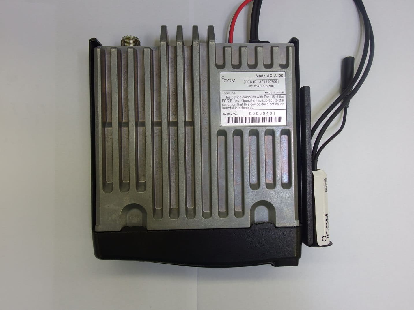
Click to zoom
Application Details
- Equipment Class
- TNB - Licensed Non-Broadcast Station Transmitter
- Date of Grant
- Dec 21, 2015
- Application Purpose
- Original Equipment
- Date of Application
- Dec 21, 2015
- Equipment Note
- VHF Air Band Transceiver
- Frequency Range
- 118.00000000 - 136.99170000
- Company
- ICOM Incorporated
- Country
- Japan
Documents & Files
Document Text
Text extracted from the exhibit documents filed with the FCC. Open a document above to read the original.
Users Manual
VHF AIR BAND TRANSCEIVERS BASIC MANUAL This device complies with Part 15 of the FCC Rules. Operation is subject to the condition that this device does not cause harmful interference. iA120 iA120E IMPORTANT READ ALL INSTRUCTIONS carefully and completely before using the transceiver. SAVE THIS INSTRUCTION MANUAL — This instruction manual contains important operating instructions for the IC-A120 and IC-A120E. The explicit definitions below apply to this instruction manual. WORDDEFINITION RWARNING! Personal injury, fire hazard or electric shock may occur. CAUTION Equipment damage may occur. NOTE If disregarded, inconvenience only. No risk of personal injury, fire or electric shock. i EXPLICIT DEFINITIONS About E-marking: Detailed installation notes for Icom mobile transceivers to be fitted into vehicles are available. Please contact your Icom dealer or distributor. CAUTION: Changes or modifications to this transceiver, not expressly approved by Icom Inc., could void your authority to operate this transceiver under FCC regulations. SUPPLIED ACCESSORIES * Used for optional unit installation. Ask the technical dealer for details. Microphone Microphone hangerMicrophone hanger cable DC power cable Mounting bracketSponges* Flat washersBracket boltsSelf-tapping screws (5×16) Spring washersMounting screws (5×12) Nuts Fuses (10 A) Self-tapping screws (3×16, for Microphone hangar) BE CAREFUL! The transceiver will become hot when operating continuously for long periods. USE the specified microphone only. Other microphones have different pin assignments and may damage the transceiver. Place the transceiver in a secure place to avoid inadvertent use by children. KEEP the transceiver away from the heavy rain, and never immerse it in the water. The transceiver meets IP54* requirements for dust-protection and splash resistance. However, once the transceiver has been dropped, dust protection and splash resistance cannot be guaranteed due to the fact that the transceiver may be cracked, or the waterproof seal damaged, and so on. *Only when the supplied microphone is attached. Icom, Icom Inc. and Icom logo are registered trademarks of Icom Incorporated (Japan) in Japan, the United States, the United Kingdom, Germany, France, Spain, Russia, Australia, New Zealand, and/or other countries. The Bluetooth word mark and logos are registered trademarks owned by Bluetooth SIG, Inc. and any use of such marks by Icom inc. is under license. All other products or brands are registered trademarks or trademarks of their respective holders. ii PRECAUTIONS R WARNING! NEVER connect the transceiver to an AC outlet. This may pose a fire hazard or result in an electric shock. R WARNING! NEVER connect the transceiver to a power source of more than 31.5 V DC. This could damage the transceiver. R WARNING! NEVER cut the DC power cable between the DC plug and fuse holder. If an incorrect connection is made after cutting, the transceiver might be damaged. R WARNING! NEVER place the transceiver where normal operation of the vehicle may be hindered or where it could cause bodily injury. CAUTION: NEVER expose the transceiver to rain, snow or any liquids. DO NOT operate or place the transceiver in areas with temperatures below –30°C (–22°F) or above +60°C (+140°F), or in areas subject to direct sunlight, such as the dashboard. DO NOT operate the transceiver without running the vehicle’s engine. The vehicle’s battery will quickly run out when the transceiver transmits while the vehicle’s engine is OFF. DO NOT place the transceiver in excessively dusty environments. DO NOT place the transceiver against walls. Otherwise heat dissipation will be obstructed. DO NOT use harsh solvents such as benzine or alcohol when cleaning, as they damage the transceiver surfaces. CAUTION: In Canada, use of 8.33 kHz Channel Spacing of this radio is strictly prohibited and shall not be used. iii NE PAS placer l'émetteur-récepteur dans un environnement excessivement poussiereux ou en plein soleil. NE PAS placer l'émetteur-récepteur contre un mur pour ne pas gêner la dispersion de la chaleur. NE PAS utiliser de solvants agressifs tels que l'essence ou l'alcool pour nettoyer le l’émetteur-récepteur, en raison des risques d'endommager la surface du l’émetteur-récepteur. ATTENTION! L’émetteur-récepteur chauffe en cas d’utilisation continue sur une longue durée. Utiliser exclusivement un microphone Icom (fourni d’origine ou en option). La repartition des broches des microphones des autres fabricants est différente et leur connexion à l’IC-A120/IC-A120E peut endommager l’émetteur-récepteur. Placer l’émetteur-récepteur hors de portée des enfants pour éviter toute utilisation inopinée. PLACEZ l'émetteur-récepteur loin d'une forte pluie et ne jamais l'immerger dans l'eau. Cet émetteur-récepteur répond aux exigences de la norme IP54* en matière de protection contre la poussière et de résistance aux éclaboussures. Toutefois, si l'émetteur-récepteur tombe par terre, la protection contre la poussière et la résistance aux éclaboussures ne peuvent être garanties, car l'appareil peut être fissuré ou le joint d'étanchéité peut être endommagé, etc. *Seulement lorsque le microphone fourni est fixé. PRÉCAUTIONS R AVERTISSEMENT! NE JAMAIS connecter l'émetteur-récepteur a une alimentation CA au risque de provoquer un incendie ou un choc electrique. R AVERTISSEMENT! NE JAMAIS brancher l’émetteur-récepteur sur une source d’alimentation de plus de 31.5 V CC. NE JAMAIS émettre lorsque le coupleur est activé (ON), alors qu'aucune antenne n'est raccordée, au risque d'endommager gravement l'émetteur-récepteur. R AVERTISSEMENT! NE JAMAIS couper le câble d’alimentation CC entre la prise CC à l’arrière de l’émetteur- récepteur et le porte fusible. L’émetteur-récepteur peut être endommagé par la suite en cas de connexion inappropriée. MISE EN GARDE: NE JAMAIS placer l’émetteur- récepteur à un emplacement où il pourrait gêner le fonctionnement normal du navire ou provoquer des blessures corporel…
Text truncated - open the document above for the full version.
Cover Letter(s)
December 21, 2015 Ultratech Engineering Labs, Inc. 3000 Bristol Circle Oakville, Ontario L6H 6G4 Subject: Certification Application under FCC 47 CFR, Parts 2 and 87 (Subpart D) - Non-broadcast Aviation Radio Services Operating in the Frequency Band 118-136.9917 MHz Applicant: ICOM Incorporated Product: VHF Air Band Transceiver Models: IC-A120 FCC ID: AFJ369700 Dear Sir/Madam: As appointed agent for ICOM Incorporated, we submit this application for FCC certification the above product. Please review all files uploaded to your electronic filing site. If you have any queries, please do not hesitate to contact us. Yours truly, Dharmajit Solanki Dharmajit Solanki Authorized Agent Group of Labs UltraTech FCC TCB & IC CB 0685 91038 1309 46390-2049 AT-1945 NVLAP LAB CODE 200093-0 SL2-IN-E-1119R Korea KCC-RRL CA2049 TL363_B TPTDP DA1300 3000 Bristol Circle, Oakville, Ontario, Canada L6H 6G4 Tel.: (905) 829-1570 Fax.: (905) 829-8050 Website: www.ultratech-labs.com Email: [email protected]
ID Label/Location Info
C - 17839 履歴A This device complies with Par t 15 of the FCC Rules. Operation is subjec t to the condition that this device does not cause harmful inter ference. FCC ID : AFJ369700 IC : 202D - 369700 MADE IN JAPAN SERIAL NO. Model : IC - A120 HVIN : 369700 - 00000000
RF Exposure Info
FCC Parts 2 and 87, Subpart D, Non-Broadcast Aviation Radio Services Page 45 VHF Air Band Transceiver, Model: IC-A120 FCC ID: AFJ369700 ULTRATECH GROUP OF LABS File #: 15ICOM410_FCC87 3000 Bristol Circle, Oakville, Ontario, Canada L6H 6G4 December 21, 2015 Tel. #: 905-829-1570, Fax. #: 905-829-8050, Email: [email protected] , Website: http://www.ultratech-labs.com All test results contained in this engineering test report are traceable to National Institute of Standards and Technology (NIST) 5.12. EXPOSURE OF HUMANS TO RF FIELD [[§§ 1.1310 & 2.1091] The criteria listed in the following table shall be used to evaluate the environmental impact of human exposure to radio-frequency (RF) radiation. FCC 47 CFR § 1.1310: 5.12.1. Method of Measurements See RSS-102 & FCC 47 CFR §§ 1.1310, 2.1091 In order to demonstrate compliance with MPE requirements, the following information is typically needed: (1) Calculation that estimates the minimum separation distance (20 cm or more) between an antenna and persons required to satisfy power density limits defined for free space. (2) Antenna installation and device operating instructions for installers (professional/unskilled users), and the parties responsible for ensuring compliance with the RF exposure requirement (3) Any caution statements and/or warning labels that are necessary in order to comply with the exposure limits (4) Any other RF exposure related issues that may affect MPE compliance FCC Parts 2 and 87, Subpart D, Non-Broadcast Aviation Radio Services Page 46 VHF Air Band Transceiver, Model: IC-A120 FCC ID: AFJ369700 ULTRATECH GROUP OF LABS File #: 15ICOM410_FCC87 3000 Bristol Circle, Oakville, Ontario, Canada L6H 6G4 December 21, 2015 Tel. #: 905-829-1570, Fax. #: 905-829-8050, Email: [email protected] , Website: http://www.ultratech-labs.com All test results contained in this engineering test report are traceable to National Institute of Standards and Technology (NIST) Calculation Method of RF Safety Distance : 22 44r EIRP r GP S Where: P: power input to the antenna in mW EIRP: Equivalent (effective) isotropic radiated power S: power density mW/cm 2 G: numeric gain of antenna relative to isotropic radiator r: distance to centre of radiation in cm 5.12.2. RF Evaluation Evaluation of RF Exposure Compliance Requirements RF Exposure Requirements Compliance with FCC Rules *Minimum calculated separation distance between antenna and persons required: 42.30 cm Manufacturer’ instruction for separation distance between antenna and persons required: 53 cm Antenna installation and device operating instructions for installers (professional/unskilled users), and the parties responsible for ensuring compliance with the RF exposure requirement Antenna installation and device operating instructions shall be provided to installers to maintain and ensure compliance with RF exposure requirements. Caution statements and/or warning labels that are necessary in order to comply with the exposure limits Refer to User’s Manual for RF Exposure Information. Any other RF exposure related issues that may affect MPE compliance None. *The minimum separation distance between the antenna and bodies of users are calculated using the following formula: RF EXPOSURE DISTANCE LIMITS S EIRP S GP r 44 P = 9.00 W, 39.54 dBm G = 0 dBi (Maximum antenna gain to be used with this device as declared by the manufacturer) S = 0.2 mW/cm 2 (General Population for By-Stander) EIRP = 39.54 dBm = 10 39.03/10 mW = 4498 mW (With 50% Duty Cycle) (Minimum Safe Distance, r) = cm S EIRP 30.42 )2.0(4 4498 4 iv SAFETY TRAINING INFORMATION Your Icom radio generates RF electromagnetic energy during transmit mode. This radio is designed for and classified as “Occupational Use Only,” meaning it must be used only during the course of employment by individuals aware of the hazards, and the ways to minimize such hazards. This radio is NOT intended for use by the “General Population” in an uncontrolled environment. • For compliance with FCC and Industry Canada RF Exposure Requirements, the transmitter antenna installation shall comply with the following two conditions: 1. The transmitter antenna gain shall not exceed 0 dBi. 2. The antenna is required to be located outside of a vehicle and kept at a distance of 53 centimeters or more between the transmitting antenna of this device and any persons during operation. For a small vehicle, the antenna as worst case, the antenna shall be located on the roof top at any place on the centre line along the vehicle in order to achieve 53 centimeters separation distance. In order to ensure this distance is met, the installation of the antenna must be mounted at least 53 centimeters away from the nearest edge of the vehicle in order to protect against exposure to bystanders. To ensure that your exposure to RF electromagnetic energy is within the FCC allowable limits for occupational use, always adhere to the following guidelines: • DO NOT operate the radio without a proper antenna attached, as this may damage the radio and may also cause you to exceed FCC RF exposure limits. A proper antenna is the antenna supplied with this radio by the manufacturer or an antenna specifically authorized by the manufacturer for use with this radio. • DO NOT transmit for more than 50% of total radio use time (“50% duty cycle”). Transmitting more than 50% of the time can cause FCC RF exposure compliance requirements to be exceeded. The radio is transmitting when the “TX” indicator appears. You can cause the radio to transmit by pressing the PTT switch. Electromagnetic Interference/Compatibility During transmissions, your Icom radio generates RF energy that can possibly cause interference with other devices or systems. To avoid such interference, turn off the radio in areas where signs are posted to do so. DO NOT operate the transmitter in areas that are sensitive to electromagnetic radiation such as hospitals, aircraft, and blasting sites. …
Text truncated - open the document above for the full version.
Test Report
VHF Air Band Transceiver Model Nos.: IC-A120 FCC ID: AFJ369700 Applicant: ICOM Incorporated 1-1-32, Kamiminami, Hirano-ku Osaka, Japan, 547-0003 Tested in Accordance with Federal Communications Commission (FCC) 47 CFR, Parts 2 and 87 (Subpart D) – Aviation Services UltraTech's File No.: 15ICOM410_FCC87 This Test report is Issued under the Authority of Tri M. Luu, BASc Vice President of Engineering UltraTech Group of Labs Date: December 21, 2015 Report Prepared by: Dharmajit Solanki Issued Date: December 21, 2015 Tested by: Wei Wu Test Dates: December 15-19, 2015 The results in this Test Report apply only to the sample(s) tested, and the sample tested is randomly selected. This report must not be used by the client to claim product endorsement by NVLAP or any agency of the US Government. UltraTech 3000 Bristol Circle, Oakville, Ontario, Canada, L6H 6G4 Tel.: (905) 829-1570 Fax.: (905) 829-8050 Website: www.ultratech-labs.com , Email: [email protected], Email: [email protected] Korea KCC-RRA 91038 1309 46390-2049 NVLAP LAB CODE 200093-0 AT-1945 SL2-IN-E- 1119R CA2049 TL363_B TPTDP DA1300 FCC Parts 2 and 87, Subpart D, Non-Broadcast Aviation Radio Services Page 1 VHF Air Band Transceiver, Model: IC-A120 FCC ID: AFJ369700 ULTRATECH GROUP OF LABS File #: 15ICOM410_FCC87 3000 Bristol Circle, Oakville, Ontario, Canada L6H 6G4 December 21, 2015 Tel. #: 905-829-1570, Fax. #: 905-829-8050, Email: [email protected] , Website: http://www.ultratech-labs.com All test results contained in this engineering test report are traceable to National Institute of Standards and Technology (NIST) TABLE OF CONTENTS EXHIBIT 1. INTRODUCTION ......................................................................................................................................... 2 1.1. SCOPE ......................................................................................................................................................................... 2 1.2. RELATED SUBMITTAL(S)/GRANT(S) .................................................................................................................. 2 1.3. NORMATIVE REFERENCES ................................................................................................................................... 2 EXHIBIT 2. PERFORMANCE ASSESSMENT .............................................................................................................. 3 2.1. CLIENT INFORMATION .......................................................................................................................................... 3 2.2. EQUIPMENT UNDER TEST (EUT) INFORMATION ............................................................................................ 3 2.3. EUT’S TECHNICAL SPECIFICATIONS ................................................................................................................. 4 2.4. LIST OF EUT’S PORTS ............................................................................................................................................. 4 EXHIBIT 3. EUT OPERATING CONDITION AND CONFIGURATIONS DURING TESTS ................................. 5 3.1. CLIMATE TEST CONDITIONS ............................................................................................................................... 5 3.2. OPERATIONAL TEST CONDITIONS & ARRANGEMENT FOR TEST SIGNALS............................................. 5 EXHIBIT 4. SUMMARY OF TEST RESULTS ............................................................................................................... 6 4.1. LOCATION OF TESTS .............................................................................................................................................. 6 4.2. APPLICABILITY & SUMMARY OF EMISSION TEST RESULTS ....................................................................... 6 4.3. MODIFICATIONS INCORPORATED IN THE EUT FOR COMPLIANCE PURPOSES ....................................... 6 4.4. DEVIATION OF STANDARD TEST PROCEDURES ............................................................................................. 6 EXHIBIT 5. MEASUREMENTS, EXAMINATIONS & TEST DATA FOR EMC EMISSIONS............................... 7 5.1. TEST PROCEDURES ................................................................................................................................................. 7 5.2. MEASUREMENT UNCERTAINTIES ...................................................................................................................... 7 5.3. MEASUREMENT EQUIPMENT USED ................................................................................................................... 7 5.4. ESSENTIAL/PRIMARY FUNCTIONS AS DECLARED BY THE MANUFACTURER ........................................ 7 5.5. RF POWER OUTPUT [§§ 2.1046 & 87.131] ............................................................................................................. 8 5.6. OCCUPIED BANDWIDTH AND EMISSION LIMITATIONS [§§ 2.1049, 87.135 & 87.139] ............................. 10 5.7. MODULATION CHARACTERISTICS - AUDIO FREQUENCY RESPONSE [§§ 2.1047(A) & 87.141(A)] ...... 24 5.8. MODULATION CHARACTERISTICS – MODULATION LIMITING [§§ 2.1047(B) & 87.141] ....................... 29 5.9. FIELD STRENGTH OF SPURIOUS EMISSIONS [§§ 2.1053, 87.139] ................................................................. 34 5.10. TRANSMITTER ANTENNA POWER SPURIOUS/HARMONIC CONDUCTED EMISSIONS [§§ 2.1051, 87.139] ...................................................................................................................................................................... 36 5.11. FREQUECNY STABILITY [§§ 2.1055 & 87.133] .................................................................................................. 43 5.12. EXPOSURE OF HUMANS TO RF FIELD [[§§ 1.1310 & 2.1091] ........................................................................ 45 EXHIBIT 6. TEST EQUIPMENT LIST ...............…
Text truncated - open the document above for the full version.
Test Setup Photos
ANNEX 1 - TEST SETUP PHOTOGRAPHS ICOM Incorporated VHF Air Band Transceiver, M/N: IC-A120 FCC ID: AFJ369700, IC: 202D-369700 Radiated Transmitter Emission Test at 3m, 30 MHz to 1GHz ANNEX 1 - TEST SETUP PHOTOGRAPHS ICOM Incorporated VHF Air Band Transceiver, M/N: IC-A120 FCC ID: AFJ369700, IC: 202D-369700 Radiated Transmitter Emission Test at 3m, 30 MHz to 1GHz ANNEX 1 - TEST SETUP PHOTOGRAPHS ICOM Incorporated VHF Air Band Transceiver, M/N: IC-A120 FCC ID: AFJ369700, IC: 202D-369700 Radiated Transmitter Emission Test at 3m, Above 1GHz ANNEX 1 - TEST SETUP PHOTOGRAPHS ICOM Incorporated VHF Air Band Transceiver, M/N: IC-A120 FCC ID: AFJ369700, IC: 202D-369700 DC Power Line Conducted Emission ANNEX 1 - TEST SETUP PHOTOGRAPHS ICOM Incorporated VHF Air Band Transceiver, M/N: IC-A120 FCC ID: AFJ369700, IC: 202D-369700 DC Power Line Conducted Emission
Contact Information
Applicant
Atsushi Tomiyama(General Manager)
Test Firm
UltraTech Engineering Labs Inc.Tri Luu
Technical Specifications
| # | Rule Parts | Frequency Range | Power Output | Emission | Tolerance |
|---|---|---|---|---|---|
| 2 | 87 | 118 MHz - 136.9917 MHz | 9 W | 5K60A3E | 5 ppm |
Other Applications from ICOM Incorporated

AFJ460100
Aug 31, 2026VHF DSC Marine Radio
Equipment Class
TNB - Licensed Non-Broadcast Station Transmitter
AFJ453700
Jul 23, 2026Mobile Transceiver
Equipment Class
DTS - Digital Transmission System
AFJ452000
Jun 02, 2026VHF DIGITAL TRANSCEIVER
Equipment Class
TNF - Licensed Non-Broadcast Transmitter Held to Face
AFJ452100
May 12, 2026UHF DIGITAL TRANSCEIVER
Equipment Class
TNF - Licensed Non-Broadcast Transmitter Held to Face
AFJ444500
Sep 12, 2024Scanning Receiver
Equipment Class
CSR - Scanning Receiver